Scaling (Concrete)
Concrete scaling is the deterioration of the upper pavement surface in Portland Cement Concrete (PCC) slabs, typically 3-13 mm deep, caused by freeze-thaw cycle...
17 min read
Concrete
Pavement
+4
Map cracking (also called crazing) is a network of shallow, fine, interconnected cracks on the concrete surface forming an irregular pattern. In FHWA LTPP, map cracking on PCC pavements is a recognized surface defect with no severity level. While often cosmetic, it can indicate poor curing, finishing issues, or alkali-silica reaction. Covers causes, severity implications, and detection.
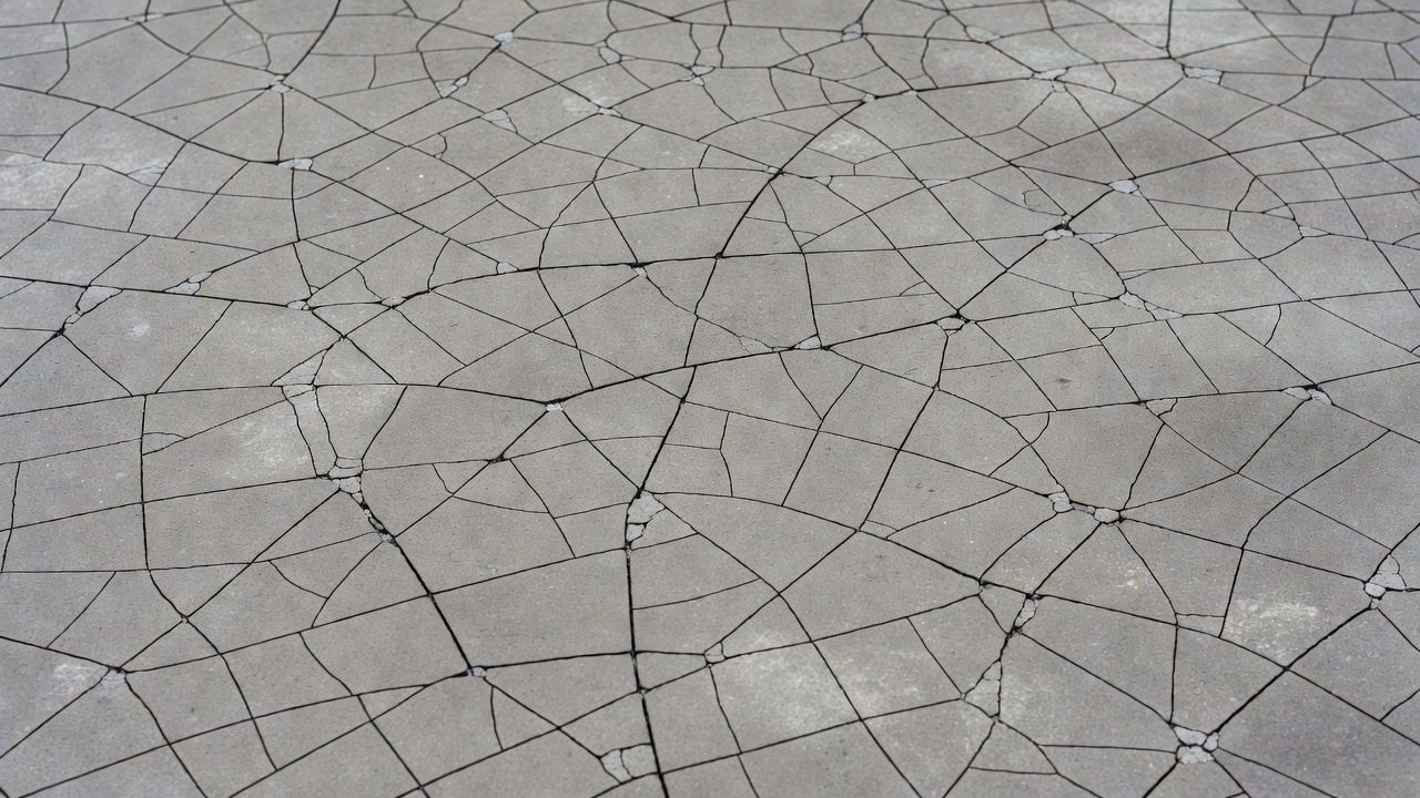
Map cracking, also known as crazing, is a surface-level distress condition in Portland Cement Concrete (PCC) characterized by a network of fine, shallow, interconnected cracks that form an irregular polygonal or roughly hexagonal pattern across the concrete surface. The term “map cracking” derives from the visual resemblance of the crack network to the irregular boundary lines on a geographic map, with individual cells or islands typically measuring between 12 and 40 millimeters (½ to 1½ inches) across. Under ASTM C856 guidelines for petrographic examination, these cracks are classified as surface-confined discontinuities that affect only the uppermost cement paste and mortar fraction of the concrete slab.
The defining morphological characteristic of map cracking is its extreme shallowness. These cracks rarely penetrate deeper than 3 millimeters (⅛ inch) into the concrete surface, remaining confined to what concrete technologists refer to as the surface mortar skin — the topmost layer composed predominantly of cement paste and fine aggregate that forms during finishing operations. This shallow depth is the single most critical factor distinguishing map cracking from structural cracking types such as longitudinal cracking, transverse cracking, corner breaks, or durability (“D”) cracking, all of which can extend through the full slab thickness under sustained loading or environmental exposure.
Within the crack network, larger cracks frequently orient themselves in the longitudinal direction of the pavement (parallel to the direction of construction or traffic), while finer transverse or randomly oriented cracks interconnect these primary fissures to complete the network pattern. When the concrete surface is dry, map cracking may be barely visible to the naked eye. The pattern becomes dramatically more apparent when the surface is wetted and begins to dry, as moisture retained in the fine cracks evaporates more slowly than from the surrounding intact surface. Over months and years of service, dirt, tire rubber residue, and other environmental contaminants become embedded in the cracks, darkening the network and making it increasingly visible even in dry conditions.
From a materials science perspective, map cracking represents a tensile stress relief mechanism occurring in the weakest zone of the concrete cross-section. The surface mortar layer, characterized by a higher water-cement ratio and greater paste content than the underlying bulk concrete, possesses lower tensile strength and higher shrinkage potential. When volumetric changes in this layer generate tensile stresses exceeding its limited tensile capacity — typically only 2 to 4 MPa for the paste fraction — the material relieves stress through the formation of a distributed micro-crack network rather than through a single dominant fracture plane. This distributed cracking behavior is what produces the characteristic map-like appearance.
The terms map cracking and crazing are used interchangeably in most concrete technology contexts, though subtle distinctions exist across different standards bodies and engineering disciplines. The American Concrete Institute (ACI), in its influential publication ACI 201.1R-08 (Guide for Conducting a Visual Inspection of Concrete in Service), uses “crazing” as the primary term, defining it as “a network of fine, shallow cracks on the surface of concrete.” ACI 224.1R-07 (Causes, Evaluation, and Repair of Cracks in Concrete Structures) similarly refers to crazing as “the development of a network of fine random cracks or fissures on the surface of concrete or mortar caused by shrinkage of the surface layer.”
The Portland Cement Association (PCA) employs both terms but tends to use “crazing” when discussing the phenomenon in the context of flatwork finishing practices and “map cracking” when discussing pavement distress identification. The FHWA Long-Term Pavement Performance (LTPP) program, in its Distress Identification Manual for the Long-Term Pavement Performance Program (FHWA-HRT-13-092, 5th Edition, May 2014), exclusively uses the term “map cracking” and includes within its definition cracking “typically associated with alkali-silica reactivity,” which represents a broadening of the term beyond the purely surface-shrinkage connotation of crazing.
A practical distinction that has emerged in pavement engineering practice is that crazing refers specifically to fine surface crack networks caused by construction-related factors (poor curing, over-finishing, high surface water-cement ratio), while map cracking may encompass surface crack networks from any cause, including alkali-silica reaction (ASR), which involves expansive gel formation deeper within the concrete matrix. Under this convention, all crazing is map cracking, but not all map cracking is crazing — ASR-induced map cracking represents a chemically driven deterioration mechanism distinct from the purely physical shrinkage mechanism of crazing.
The FAA PAVER™ distress identification system for airfield pavements does not maintain a separate distress type called “map cracking” or “crazing.” Instead, the phenomenon is captured through three interrelated distress categories: Alkali-Silica Reaction — ASR (Code 76), defined as cracking of the concrete pavement often in a map pattern with possible gel staining; Shrinkage Cracks (Code 73), which captures non-structural hairline crack patterns; and Scaling/Crazing (Code 70), where low-severity crazing is counted only if it is expected to progress to more severe scaling within two to three years. This distributed classification reflects the airfield pavement community’s operational focus on safety consequences — particularly Foreign Object Debris (FOD) potential — rather than on precise crack morphology.
| Feature | Typical Crazing (Construction-Related) | ASR-Induced Map Cracking |
|---|---|---|
| Primary cause | Surface shrinkage during curing | Expansive alkali-silica gel formation |
| Depth | ≤3 mm (surface only) | Variable; can extend deeper |
| Crack width | Hairline (<0.5 mm) | Can widen to 1–2 mm over time |
| Associated features | None | Gel exudation, staining, pop-outs |
| Progression | Stabilizes after initial drying | Progressive over years |
| Structural significance | Cosmetic only | Potentially significant |
| FOD risk | Minimal initially | Moderate to high as cracks widen |
Inadequate or delayed curing is the single most frequently cited cause of map cracking in concrete pavements. When fresh concrete is placed and finished, the surface is exposed to ambient conditions — air temperature, relative humidity, wind speed, and solar radiation — that collectively govern the rate of evaporative water loss. The American Concrete Institute specifies in ACI 308R-16 (Guide to External Curing of Concrete) that curing should commence immediately after final finishing and continue for a minimum of seven days under normal conditions, or longer when supplementary cementitious materials such as fly ash or ground granulated blast-furnace slag are used.
When curing is omitted or delayed, the surface mortar layer loses moisture to evaporation at a rate that can exceed the rate at which bleed water from the underlying concrete can replenish it. This creates a moisture gradient through the slab thickness, with the surface layer experiencing the greatest moisture deficit and consequently the greatest shrinkage strain. The differential shrinkage between the rapidly drying surface and the still-moist interior generates tensile stresses in the surface layer. Because the surface paste, with its higher water-cement ratio from finishing operations, has lower tensile strength than the bulk concrete, it cracks in the distributed network pattern characteristic of map cracking.
The critical evaporation rate above which map cracking becomes likely is approximately 1.0 kg/m² per hour, as established by ACI 305R-20 (Guide to Hot Weather Concreting). This rate can be exceeded even in moderate weather conditions when wind speeds are high or relative humidity is low. The use of evaporation retarders — monomolecular films sprayed onto the fresh concrete surface immediately after screeding — can reduce evaporation rates by up to 80%, providing a critical protection window between finishing operations and the application of final curing measures.
Over-finishing of concrete surfaces — particularly over-troweling with power trowels on slabs that will not receive subsequent coverings — is a major contributor to map cracking. Each pass of a trowel or float across the concrete surface depresses coarse aggregate particles downward and brings a layer of cement paste and fine sand to the surface. When troweling is continued beyond the point necessary to achieve the desired surface texture and flatness, the surface layer becomes progressively enriched in cement paste and depleted of coarse aggregate.
This paste-enriched surface layer, typically 2 to 5 mm thick, has fundamentally different properties from the bulk concrete: a higher water-cement ratio (since bleed water continues to rise and accumulate), higher cement content, negligible coarse aggregate content, and consequently higher drying shrinkage potential and lower tensile strength. The absence of coarse aggregate particles in this layer removes the crack-arresting mechanism that coarse aggregate normally provides — in properly proportioned concrete, propagating micro-cracks must navigate around aggregate particles, consuming energy and limiting crack extension. Without this aggregate interlock, the paste-rich surface layer is highly susceptible to the distributed cracking pattern of crazing.
A particularly damaging practice is troweling bleed water back into the surface. When finishers observe bleed water sheen on the concrete surface and trowel it in rather than allowing it to evaporate or removing it by dragging a hose across the surface, they are effectively increasing the water-cement ratio of the surface layer to values that can exceed 0.60 or even 0.70 — far higher than the 0.40 to 0.50 typical of durable concrete. This surface water-cement ratio elevation dramatically increases the porosity, permeability, and shrinkage potential of the surface layer. ACI 302.1R-15 (Guide to Concrete Floor and Slab Construction) explicitly warns against this practice and recommends waiting until bleed water has completely evaporated from the surface before commencing final troweling operations.
Alkali-silica reaction is a chemical deterioration mechanism that can produce a map cracking pattern distinctly different from that caused by construction-related surface shrinkage. ASR occurs when reactive forms of silica present in certain aggregates react with alkali hydroxides (sodium and potassium) dissolved in the concrete pore solution. The reaction product is an alkali-silica gel that imbibes water and expands, generating internal pressures that can exceed the tensile capacity of the surrounding cement paste.
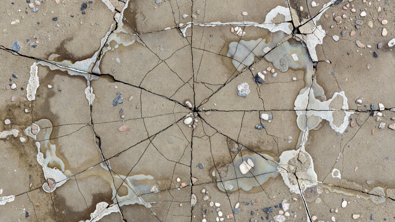
The map cracking pattern produced by ASR differs from curing-related crazing in several diagnostic ways. ASR-induced cracks tend to be wider (often 0.5 to 2.0 mm after several years of reaction), may exhibit whitish, brownish, or grayish gel exudations at crack surfaces, and often display associated pop-outs — small conical fragments that detach from the surface above reactive aggregate particles. The crack network in ASR-affected concrete typically extends deeper than the surface mortar layer, sometimes penetrating 25 mm or more into the slab. Petrographic examination per ASTM C856 (Standard Practice for Petrographic Examination of Hardened Concrete) can confirm ASR by identifying reaction rims around aggregate particles, gel-filled micro-cracks within aggregates, and gel deposits in air voids.
ASR requires three conditions to occur simultaneously: reactive silica in the aggregate, sufficient alkalis in the pore solution (typically expressed as Na₂O equivalent exceeding 0.60% by mass of cement, or approximately 3.0 kg/m³ of concrete), and sufficient moisture (relative humidity above approximately 80% within the concrete). In airfield pavements, where deicing chemicals may introduce additional alkalis and where precipitation provides abundant moisture, ASR can progress more rapidly than in many other concrete environments. The FAA Advisory Circular 150/5380-8 (Handbook for Identification of Alkali-Silica Reactivity in Airfield Pavements) provides specific guidance for identifying and managing ASR in airport concrete.
Freeze-thaw cycling interacts with map cracking in two distinct ways. First, existing map cracks — whether from poor curing or ASR — serve as water entry pathways. When water-saturated cracks freeze, the approximately 9% volumetric expansion of water-to-ice conversion exerts hydraulic pressure on crack walls, potentially widening and deepening the cracks incrementally with each freeze-thaw cycle. This progressive deterioration can transform initially cosmetic crazing into more severe scaling over multiple winter seasons.
Second, freeze-thaw damage to non-air-entrained or inadequately air-entrained concrete can produce a surface deterioration pattern that mimics map cracking. Without a properly distributed system of entrained air voids (typically 4% to 8% air content with a spacing factor below 0.20 mm, per ASTM C457), freezing water within the capillary pore system of the cement paste generates destructive internal pressures. The resulting micro-cracking can create a network pattern at the surface that superficially resembles crazing but is distinguished by its association with surface scaling — the progressive loss of surface mortar — and by the absence of the neat polygonal cell structure characteristic of true map cracking. ASTM C672 (Standard Test Method for Scaling Resistance of Concrete Surfaces Exposed to Deicing Chemicals) provides a standardized method for evaluating this type of surface deterioration.
Carbonation of the surface concrete layer — the chemical reaction between atmospheric carbon dioxide (CO₂) and calcium hydroxide in the hydrated cement paste to form calcium carbonate — produces a measurable volumetric shrinkage of the cement paste. This carbonation shrinkage, while typically smaller in magnitude than drying shrinkage, can contribute to map cracking in specific circumstances, particularly when unvented combustion heaters are used during cold-weather concrete construction. These heaters can elevate CO₂ concentrations in the enclosure to levels many times higher than ambient atmospheric levels (which are approximately 0.04% or 420 ppm), accelerating surface carbonation. The carbonation reaction also reduces the pH of the concrete pore solution from approximately 13 to below 9, which, in reinforced concrete, eliminates the passive protective layer on embedded steel reinforcement — though this is a corrosion concern rather than a cracking concern for map cracking specifically.
The FHWA Long-Term Pavement Performance (LTPP) program, the most comprehensive pavement performance research initiative ever undertaken, classifies map cracking as a distinct distress type under the Surface Defects category for Portland Cement Concrete pavements. The Distress Identification Manual for the Long-Term Pavement Performance Program (FHWA-HRT-13-092, 5th Edition, May 2014) provides the authoritative definition and measurement protocol used by highway agencies across the United States and referenced internationally.
For Jointed Plain Concrete Pavement (JCP), map cracking is designated as Distress JCP 8a. For Continuously Reinforced Concrete Pavement (CRCP), it is designated as Distress CRCP 4a. The definition provided in both cases is: “A series of cracks that extend only into the upper surface of the slab. Larger cracks frequently are oriented in the longitudinal direction of the pavement and are interconnected by finer transverse or random cracks.” The LTPP glossary further clarifies that map cracking “includes cracking typically associated with alkali-silica reactivity,” explicitly broadening the definition beyond construction-related crazing.
A critical feature of the LTPP classification is that no severity levels are defined for map cracking. Unlike other PCC distresses such as longitudinal cracking (which has low, moderate, and high severity levels based on crack width and spalling) or corner breaks (similarly leveled), map cracking is treated as a binary condition: present or not present. The measurement protocol records the number of occurrences and the total affected area in square meters. When an entire pavement section is affected by map cracking, it is recorded as a single occurrence encompassing the full section area.
| Pavement Type | Distress Code | LTPP Category | Severity Levels | Unit of Measure |
|---|---|---|---|---|
| Jointed Plain Concrete (JCP) | JCP 8a | Surface Defects | None defined | Number + m² |
| Continuously Reinforced Concrete (CRCP) | CRCP 4a | Surface Defects | None defined | Number + m² |
| Jointed Reinforced Concrete (JRC) | Not separately coded | — | — | — |
This lack of severity grading reflects the research-oriented nature of the LTPP program. Since map cracking is generally regarded as non-structural, the program’s emphasis on load-related deterioration modeling did not require detailed severity data for this particular distress. For operational pavement management systems, however — particularly those serving airfield pavements — the absence of severity levels represents a gap that the FAA PAVER system addresses through its ASR and shrinkage crack distress categories with defined low, medium, and high severity criteria.
Airfield pavements present unique requirements that elevate the significance of map cracking beyond what would be considered acceptable for highway pavements. The two overriding concerns are Foreign Object Debris (FOD) prevention and surface friction maintenance, both of which are directly addressed in ICAO Annex 14 — Aerodromes, Volume I — Aerodrome Design and Operations, and its supporting guidance in ICAO Doc 9157 — Aerodrome Design Manual, Part 3 — Pavements.
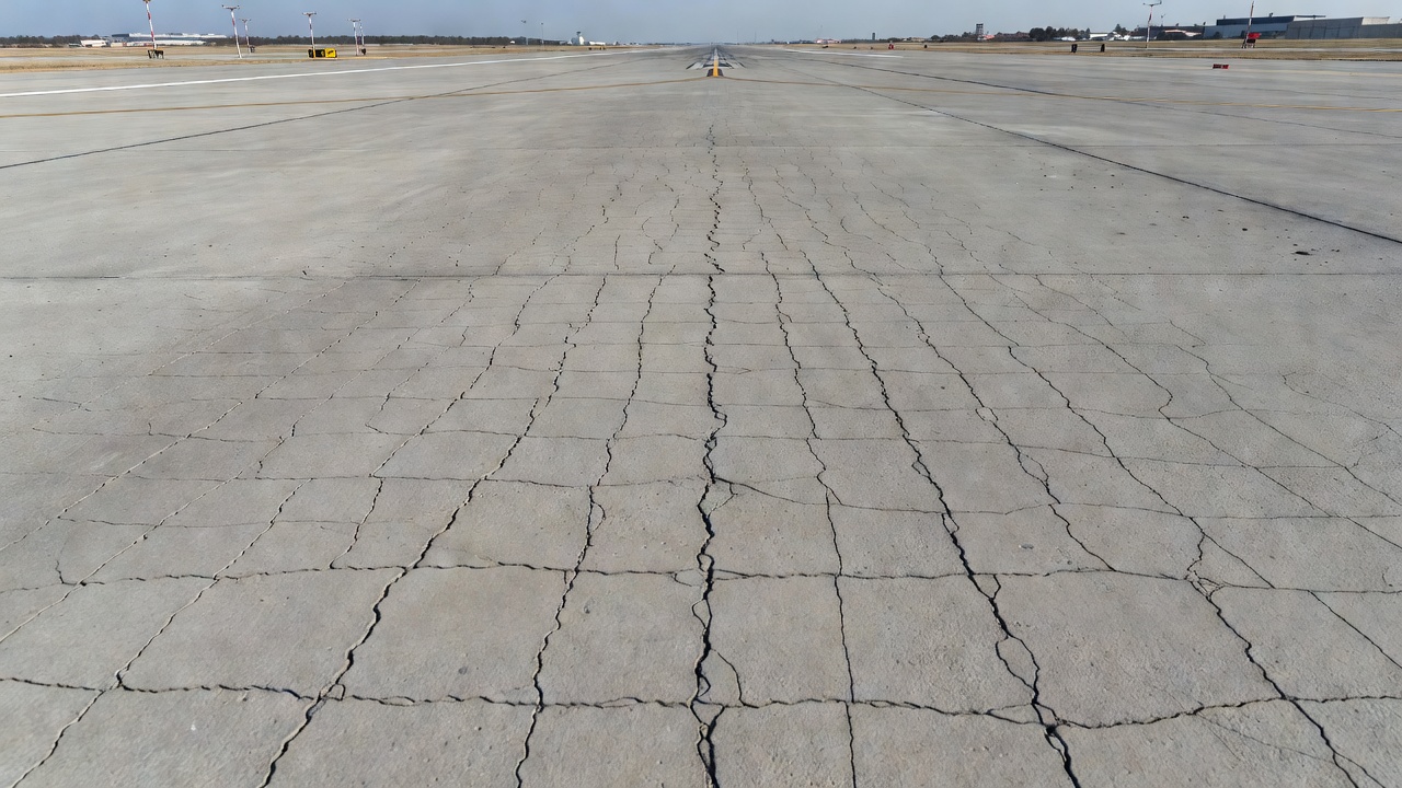
FOD, defined as any object located in an inappropriate location in the airport environment that has the capacity to injure personnel or damage aircraft, is a paramount safety concern. Even superficial map cracking can evolve into FOD generation if crack edges spall or if the network of fine cracks coalesces to create loose surface fragments. Jet blast from aircraft engines, particularly from large commercial and military aircraft during takeoff, can dislodge weakly bonded surface mortar between closely spaced map cracks. A piece of concrete as small as 12 mm (½ inch) in any dimension, if ingested by a jet engine, can cause damage costing hundreds of thousands of dollars and potentially create a catastrophic safety hazard. Consequently, the FAA PAVER system treats high-severity ASR cracking — which includes map-pattern cracking with loose fragments — as a condition where no other distress should be counted on that slab, since the FOD potential overrides all other deterioration considerations.
Surface friction is the second critical concern. ICAO Annex 14, Attachment A, Section 2, specifies that runway pavement surfaces must be maintained to provide acceptable friction characteristics under all weather conditions. Map cracking, by disrupting the continuous surface texture of the pavement, can reduce both macrotexture (governing drainage and wet friction at aircraft speeds) and microtexture (governing low-speed friction). While the direct effect of hairline crazing on friction measurements is typically small, the long-term progression of map cracking into scaling, surface raveling, and pop-outs can create localized areas of significantly reduced friction. Regular friction testing using continuous friction measuring equipment (CFME) per ICAO Doc 9137 — Airport Services Manual, Part 2 — Pavement Surface Conditions is standard practice, and any distress condition that may accelerate friction degradation must be monitored and managed.
The Pavement Condition Index (PCI) methodology standardized in ASTM D5340-11 (Standard Test Method for Airport Pavement Condition Index Surveys) and STANAG 7181 (NATO standard for airfield PCI) incorporates map-cracking-type distresses through three categories:
At high severity ASR, the deduct value impact on PCI is substantial — typically 20 to 40 points per affected slab, depending on density — reflecting the serious safety and operational implications for airfield pavements.
The fundamental question facing pavement engineers evaluating map-cracked concrete is whether the observed condition represents a cosmetic surface defect or a symptom of deeper structural deterioration. The answer depends on a careful analysis of depth, cause, and progression.
Cosmetic crazing — the shallow, construction-related surface crack network — is, by definition, structurally benign. The cracks are confined to the top 2–3 mm of paste-rich mortar and do not extend into the load-bearing concrete. In interior slabs on grade where appearance is not critical, cosmetic crazing requires no remediation. On highway pavements, the LTPP program’s decision not to assign severity levels to map cracking implicitly acknowledges that this distress type, in its pure form, does not affect structural capacity or predicted service life.
However, ASR-induced map cracking occupies a fundamentally different position on the structure-versus-cosmetic spectrum. ASR is a progressive, volumetric instability that affects the entire concrete cross-section, not merely the surface. The map cracking visible at the surface is the external manifestation of internal expansion, cracking, and gel formation occurring throughout the reactive aggregate locations within the concrete. Over periods of 5 to 20 years, ASR can:
The depth criterion provides a practical field indicator. If cracking can be demonstrated — through coring, petrographic examination, or ultrasonic pulse velocity testing — to extend more than approximately 5 mm below the surface, the distress should be considered potentially structural rather than cosmetic. ASTM C856 petrographic examination remains the definitive method for determining crack depth, origin, and the presence of ASR gel. ASTM C597 pulse velocity testing can provide a non-destructive indication of internal cracking density, with pulse velocity reductions of more than 10% to 15% relative to sound concrete of the same mix suggesting significant internal deterioration.
On airfield pavements, the FAA PAVER system addresses this distinction through its ASR severity levels. Low severity ASR (minimal cracks, tight surface, cracks ≤1 mm, no FOD potential) may not require immediate structural intervention. Medium severity ASR (increased cracking, some FOD potential, cracks may be spalled) requires active management. High severity ASR (extensive cracking, definite FOD potential, loose pieces, significant disintegration) typically requires slab replacement or major rehabilitation.
Accurate differentiation of map cracking from other concrete cracking types is essential for correct distress identification, PCI calculation, and maintenance planning. The following distinctions apply:
D-Cracking (Durability Cracking) — designated as JCP Distress 7 / CRCP Distress 3 in the LTPP system — is a distress type associated with the use of certain non-durable coarse aggregates susceptible to freeze-thaw deterioration when critically saturated. D-cracking is distinguished from map cracking by its characteristic location: it begins adjacent to joints, edges, and cracks where water can enter the concrete, and it produces closely spaced, crescent-shaped cracks that run roughly parallel to the joint or edge. Unlike map cracking, which covers broad slab areas, D-cracking is concentrated in bands adjacent to moisture entry points. D-cracking also produces a distinctive dark staining of the concrete near cracks and, when tapped with a hammer, produces a characteristic dull or hollow sound indicating subsurface disintegration. The FAA PAVER system specifies that when D-cracking is present, scaling should not be recorded separately on the same slab to avoid double-counting related deterioration.
Structural Longitudinal and Transverse Cracking is distinguished from map cracking by linearity, depth, and mechanism. Longitudinal cracks run parallel to the pavement centerline; transverse cracks run perpendicular to it. Both are typically singular or few in number per slab, may extend full-depth through the slab, and are usually caused by a combination of thermal stresses, moisture gradients, traffic loading, and subgrade restraint. Crack widths for structural cracking typically exceed 1 mm and may reach 5 mm or more with spalling. Map cracking, by contrast, is multi-directional, shallow, fine, and distributed across the slab surface.
Plastic Shrinkage Cracking occurs in fresh concrete before final set, typically within the first few hours after placement, when the rate of surface evaporation exceeds the rate of bleed water rising to the surface. These cracks tend to be longer, more isolated, and roughly parallel to each other, oriented perpendicular to the wind direction. They can be deeper than map cracks — sometimes extending 25 to 100 mm into the slab — but lack the interconnected network pattern. Plastic shrinkage cracks typically appear within 1 to 6 hours after placement, whereas map cracking from curing deficiencies may not become visible for days or weeks.
Corner Breaks are structural cracks that intersect the slab corner at approximately 45 degrees, extending through the full slab thickness. They are load-associated distresses related to insufficient slab corner support, high corner deflections under traffic, or loss of load transfer at joints. A corner break is identified by the presence of a crack that intersects both the transverse joint (or crack) and the longitudinal joint (or edge), forming a triangular piece. The crack is typically wider at the corner and narrows as it extends inward. Map cracking, even in its most extensive form, does not produce this geometric pattern.
Shattered Slab represents the end-stage of multiple intersecting structural cracks. Defined in the LTPP system as a slab divided by cracks into four or more pieces, a shattered slab is distinguished from map cracking by the size of the crack-bounded pieces (typically >0.1 m² for shattered slab versus 100–1600 mm² for map cracking cells) and by the full-depth nature of the dividing cracks. The FAA PAVER system specifies that when medium or high severity shattered slab is recorded, no other distress is counted.
Detection of map cracking ranges from simple visual observation to sophisticated automated systems, with the appropriate method determined by the purpose of the survey (network-level condition assessment versus project-level forensic investigation) and the operational context (highway versus airfield).
Visual inspection remains the most common detection method and, when conducted by trained inspectors following standardized protocols, provides reliable identification of map cracking presence and approximate extent. The optimal conditions for visual detection are when the pavement surface is damp — after light rain or following deliberate wetting — and observed under low-angle lighting, such as early morning or late afternoon sunlight. The moisture differential between intact surface and cracked areas, combined with the shadowing effect of oblique light, makes even hairline map cracking clearly visible. The ACI 201.1R visual inspection guide recommends documenting the affected area, photographing representative crack patterns with a scale reference, and noting the presence or absence of associated features such as gel staining, pop-outs, or surface scaling.
Close-range photogrammetry and high-resolution digital imaging have become increasingly important for network-level pavement condition surveys. The FHWA-RC-20-0005 report (Developing Guidelines for Cracking Assessment for Use in Vendor Selection Process, March 2020) notes that map cracking is one of the most challenging distresses for automated crack detection systems because of its fine crack widths (often below 0.5 mm), distributed pattern, and low contrast with the surrounding concrete. Modern systems achieving resolutions of 1 mm per pixel or better, combined with machine learning algorithms trained on verified map cracking datasets, are improving detection rates. However, the FHWA report recommends that automated cracking data be validated against ground reference measurements using statistically valid methods such as a paired t-test for equivalence, with typical acceptance tolerances of ±4% to ±5% for cracking percent.
Crack comparators and microscopes provide quantitative crack width measurement in the field. Optical crack width comparators — transparent cards with calibrated line widths printed at known scales — allow rapid estimation of crack width to within approximately 0.1 mm. Handheld crack microscopes with 40× to 100× magnification and integrated measuring reticles can resolve crack widths to 0.02 mm, sufficient for distinguishing cosmetic crazing (typically <0.3 mm) from wider ASR-induced cracks (0.5–2.0 mm). The crack width threshold of approximately 0.5 mm is significant for airfield pavements, as cracks wider than this can trap aircraft tire rubber during landings and contribute to FOD generation.
Dye penetrant testing, adapted from the non-destructive testing methods used for metals under ASTM E1417, can be used to enhance the visibility of fine map cracking for documentation purposes. A low-viscosity colored dye is applied to the surface, allowed to penetrate the crack network by capillary action, and the excess is removed. The dye retained in the cracks provides high-contrast crack mapping. This method is particularly useful for forensic investigations and for creating permanent visual records, though it is too labor-intensive for routine network-level surveys.
Petrographic examination per ASTM C856 is the definitive method for confirming ASR as the cause of map cracking and for determining crack depth and origin. A 100 mm diameter core is extracted, impregnated with fluorescent-dyed epoxy under vacuum, sectioned, and examined using stereo microscopy and, if indicated, scanning electron microscopy with energy-dispersive X-ray spectroscopy (SEM-EDS). Petrographic indicators of ASR include: reaction rims around reactive aggregate particles; gel-filled cracks within aggregates and extending into the cement paste; alkali-silica gel deposits in air voids; and elevated alkali concentrations detected by EDS. The depth to which ASR features extend provides critical information for assessing whether the deterioration is surface-confined or structural.
Ultrasonic pulse velocity (UPV) per ASTM C597 provides a non-destructive indication of internal concrete quality. Pulse velocity reductions of more than approximately 10% relative to sound concrete of similar composition suggest significant internal micro-cracking, which in the context of visible surface map cracking would point toward ASR rather than cosmetic crazing. UPV can be performed in both direct transmission (through the slab thickness) and indirect transmission (along the surface) configurations, though the surface measurements better characterize the zone affected by map cracking.
The appropriate maintenance or repair response to map cracking depends on a systematic assessment of cause, depth, severity, traffic criticality, and operational context. The following hierarchy of interventions reflects the range from cosmetic acceptance to major rehabilitation:
No Action (Monitor Only) — Applicable to cosmetic crazing on pavements where surface appearance is not critical and where no FOD generation or friction loss has been observed. Interior building slabs, secondary roadway shoulders, and non-movement-area airfield pavements away from aircraft paths may fall into this category. Even under a no-action decision, periodic monitoring is warranted to detect any progression from crazing to scaling or any widening of cracks that could signal undiagnosed ASR.
Surface Sealers — Penetrating sealers based on silane, siloxane, or silane-siloxane blends can be applied to map-cracked concrete to reduce water ingress without forming a surface film that would alter friction characteristics. These materials penetrate 2 to 8 mm into the concrete, lining capillary pores and fine cracks with a hydrophobic layer while maintaining vapor permeability (allowing internal moisture to escape). For airfield pavements, the FAA requires that any surface treatment not reduce pavement friction below acceptable levels, and friction testing before and after application is essential. Epoxy-based crack sealers can fill individual wider cracks — those exceeding approximately 0.5 mm — but are not practical for the fine, distributed crack network of true map cracking.
Thin Polymer Overlays — Polymer concrete overlays, typically 6 to 12 mm thick and composed of epoxy or methacrylate binders with fine aggregate, can restore surface integrity, seal the underlying map-cracked surface, and provide a new wearing course with excellent friction characteristics. The overlay bonds to the prepared concrete substrate and bridges fine cracks. Surface preparation — typically shotblasting or grinding to remove laitance and provide a sound bonding surface — is critical to overlay performance. On airfield pavements, the overlay material must demonstrate resistance to jet fuel, hydraulic fluid, and deicing chemicals, as well as adequate bond strength under the thermal cycling and dynamic loading conditions of aircraft operations. The FAA Engineering Brief No. 66 provides guidance on the use of thin polymer overlays on airfield concrete pavements.
Diamond Grinding — Diamond grinding removes a thin layer (typically 2 to 6 mm) of the concrete surface using closely spaced diamond-impregnated blades, physically eliminating the crazed surface layer and exposing sound concrete beneath. This method simultaneously restores surface smoothness, improves friction through the creation of a corduroy surface texture, and eliminates the map-cracked zone. For ASR-affected concrete, grinding can temporarily restore surface quality, but if the underlying concrete continues to expand, the map cracking pattern may re-emerge over a period of years. The International Grooving and Grinding Association (IGGA) provides detailed specifications for diamond grinding of concrete pavements, including airfield applications.
Lithium Compound Treatment for ASR — When ASR is confirmed as the cause of map cracking, treatment with lithium-based compounds — typically lithium nitrate or lithium hydroxide — can mitigate further reaction. Lithium ions compete with sodium and potassium ions for incorporation into the alkali-silica reaction product, forming a non-expansive lithium-silicate gel rather than the expansive sodium- or potassium-silicate gel. The treatment is applied as a topical spray that penetrates the concrete surface, with dosage rates typically in the range of 0.5 to 1.0 L/m² depending on concrete porosity and the severity of existing damage. The effectiveness of lithium treatment depends on achieving adequate penetration depth and on the extent of ASR progression at the time of treatment — it is most effective as a mitigation measure early in the reaction process when expansion is still limited.
Full-Depth Slab Replacement — For airfield pavements exhibiting high-severity ASR map cracking with active FOD generation, or for slabs where the cumulative effect of ASR has reduced structural capacity below operational requirements, full-depth slab replacement is the definitive repair. Replacement slabs should be constructed with aggregates of proven non-reactive quality, low-alkali cement (Na₂O equivalent ≤0.60%), and, where appropriate, supplementary cementitious materials such as Class F fly ash (15% to 30% replacement) or slag cement (35% to 50% replacement) that have been demonstrated through ASTM C1567 testing to control ASR expansion. In the airfield environment, rapid-strength concrete mixes capable of achieving traffic-opening strengths within 4 to 6 hours are often specified to minimize operational disruption during overnight construction windows.
The following table summarizes the applicability of each repair strategy:
| Repair Method | Applicable Cause | Typical Depth | Airfield-Suitable | Approximate Service Life |
|---|---|---|---|---|
| No action / monitor | Cosmetic crazing only | N/A | Yes (non-critical areas) | N/A |
| Silane/siloxane sealer | Surface shrinkage crazing | Surface (2–8 mm penetration) | Yes (verify friction) | 5–10 years |
| Thin polymer overlay | Crazing, early ASR | 6–12 mm overlay | Yes (fuel-resistant type) | 10–15 years |
| Diamond grinding | Crazing, moderate ASR | 2–6 mm removal | Yes | 5–15 years (ASR may recur) |
| Lithium treatment | Confirmed ASR | Penetration varies | Yes | Variable; monitoring required |
| Full-depth replacement | Severe ASR, FOD active | Full slab | Yes | 20–30+ years |
Preventing map cracking begins at the mix design stage and extends through every phase of concrete placement, finishing, and curing. The following measures, drawn from ACI, PCA, and FAA guidance, represent best practice for producing durable concrete surfaces resistant to map cracking:
Mix design should target a moderate slump — typically 75 to 125 mm (3 to 5 inches) — achieved through optimized aggregate gradation and water-reducing admixtures rather than through excess water addition. The water-cementitious materials ratio should not exceed 0.45 for pavement concrete exposed to weather and deicing chemicals, and should ideally be maintained at or below 0.40 for airfield pavement concrete. Air entrainment of 5% to 8% should be provided for freeze-thaw resistance. For ASR prevention, the total alkali content of the concrete should be limited to 3.0 kg/m³ Na₂O equivalent, and reactive aggregates should be avoided or used only in combination with proven ASR-mitigating SCMs at dosages verified by ASTM C1567 or ASTM C1293 testing.
Finishing must be timed correctly. Floating and troweling should commence only after all bleed water has evaporated from the surface. If evaporation rates are high (approaching 1.0 kg/m²/hr), evaporation retarders should be applied. Power troweling should be limited to the minimum number of passes needed to achieve the specified surface texture and flatness — typically no more than two passes with a float and two with a trowel — and should never continue after the concrete has begun to stiffen. The practice of sprinkling dry cement onto the surface to absorb bleed water must be strictly prohibited, as it creates the paste-rich, high-shrinkage surface layer that is the direct cause of crazing.
Curing must begin immediately after final finishing and texturing operations. For airfield concrete, a two-stage curing approach is often employed: an initial application of a liquid membrane-forming curing compound (meeting ASTM C309 requirements) applied at the manufacturer’s recommended coverage rate (typically 5.0 m²/L for a single coat), followed within 24 hours by the application of water through ponding, soaker hoses, or continuously wetted burlap for a minimum of 7 days at temperatures above 10°C. In hot weather conditions (air temperature above 30°C or concrete temperature above 35°C), the curing period should be extended to 10 days, and supplementary measures such as sunshades or evaporative cooling may be necessary to control surface temperatures. Cold-weather curing (air temperature below 5°C) requires insulation blankets or heated enclosures, with careful attention to preventing carbonation from unvented heaters.
Quality control testing should verify slump, air content, and concrete temperature at the point of placement, and should include the casting of test specimens cured under the same conditions as the pavement for compressive strength verification. For critical airfield pavement applications, trial slab placements are recommended to validate mix design, finishing procedures, and curing protocols before full-scale construction commences.
Map cracking — whether referred to as crazing, pattern cracking, or alligator cracking in various contexts — is a surface-level concrete distress that, in its cosmetic form, does not threaten structural integrity but, in its ASR-associated form, can signal progressive internal deterioration with significant implications for pavement service life, safety, and maintenance costs. The distinction between these two manifestations — one benign, one potentially serious — is the central diagnostic challenge for pavement engineers and airport maintenance managers.
The FHWA LTPP classification provides a standardized framework for highway pavement condition documentation, while the FAA PAVER system translates the phenomenon into operationally meaningful terms for airfield applications, where FOD prevention and friction maintenance are overriding priorities. Detection relies on a combination of visual inspection, quantitative crack measurement, and advanced petrographic analysis when ASR is suspected. Repair strategies range from acceptance and monitoring through surface treatments, overlays, and grinding to full-depth replacement, with the appropriate intervention determined by cause, depth, severity, and operational criticality.
The most effective approach to map cracking remains prevention through sound concrete construction practices: controlled mix design, properly timed finishing, immediate and thorough curing, and — for ASR mitigation — careful aggregate selection and the use of proven supplementary cementitious materials. These preventive measures, when consistently applied, produce concrete surfaces that resist the formation of map cracking and maintain their integrity, friction, and FOD-free condition throughout decades of service on the world’s most demanding pavements.
Identify map cracking, ASR, and other concrete defects early with expert pavement inspection and condition assessment. Protect your airfield infrastructure and maintain operational safety with data-driven maintenance planning.
Concrete scaling is the deterioration of the upper pavement surface in Portland Cement Concrete (PCC) slabs, typically 3-13 mm deep, caused by freeze-thaw cycle...
Alligator cracking — also called fatigue cracking — is an interconnected crack pattern resembling alligator skin that indicates structural failure of the asphal...
D-cracking is a pattern of closely spaced crescent-shaped cracks near joints, edges, and cracks in PCC pavements, caused by freeze-thaw deterioration of suscept...