Welded wire reinforcement (WWR) consists of cold-drawn steel wires welded into a square or rectangular grid, used as non-structural reinforcement in concrete slabs-on-grade and pavements for crack control. Lighter and faster to place than rebar mats. Covers WWR types, placement requirements, and inspection for correct positioning.
Welded Wire Reinforcement — Definition and Configuration
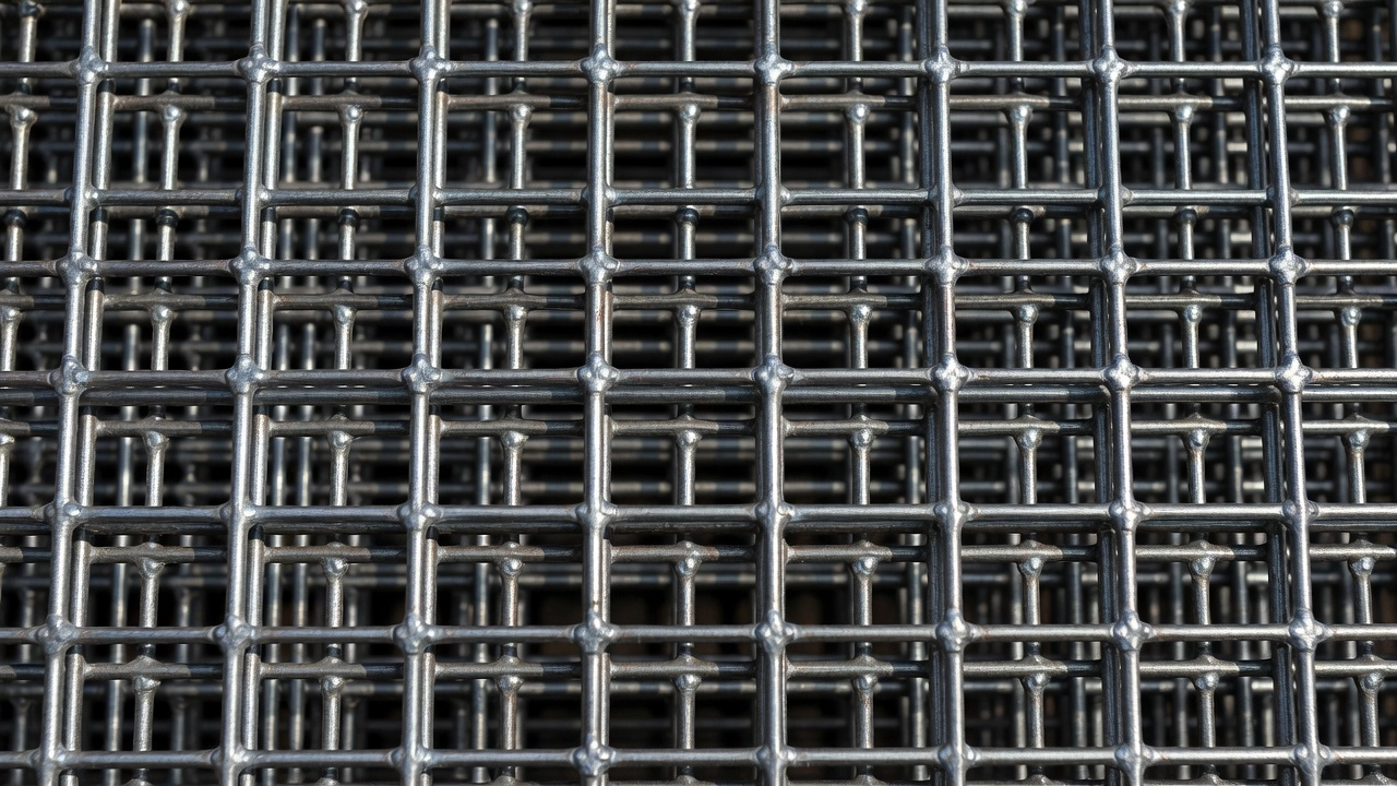
Welded wire reinforcement (WWR), also referred to historically as welded wire fabric (WWF), is a prefabricated steel reinforcement product manufactured from cold-drawn or cold-rolled steel wires arranged in a orthogonal grid pattern and resistance-welded at all intersections. Per ASTM A1064/A1064M — the governing material standard — WWR is defined as a material composed of cold-worked steel wire with either plain (smooth) surfaces or indented rib deformations that conform to specified geometric requirements. The cold-working process consists of drawing hot-rolled steel rod through a series of dies or cassettes to reduce the wire diameter to project-specific dimensions while simultaneously increasing the yield strength of the steel through strain hardening.
The manufacturing sequence begins with controlled-quality, hot-rolled smooth rods that are cold-worked through successive reduction dies, producing wires with higher yield strength and consistent mechanical properties. These wires are then automatically fed into high-speed resistance welding machines where electrical current passes through the intersecting wire junctions. The electrical resistance at each intersection generates heat that fuses the two wires together into a homogeneous section — no consumable electrode material is used in this process. The resulting mat maintains precise wire spacings locked into position by the welds, ensuring that the reinforcement geometry specified by the engineer is faithfully reproduced in the finished product.
Wire Size Designation follows a standardized letter-number system governed by ASTM A1064. Smooth wires are designated with the prefix W followed by a number representing the cross-sectional area of the wire in hundredths of a square inch. For example, W4.0 denotes a smooth wire with a cross-sectional area of 0.04 in² (approximately 0.226 in. diameter). Deformed wires use the prefix D with the same area convention — D20 indicates a deformed wire with 0.20 in² cross-sectional area. The metric equivalents use the prefixes MW and MD followed by the area in square millimeters. WWR is available in wire sizes ranging from W0.5 (lightest, approximately 0.080 in. diameter) up to W31 (largest, approximately 0.625 in. or 5/8 in. diameter), with deformed wires available from D4.0 through D31.0.
The complete WWR style designation conveys four pieces of information in a compact format. A typical designation reads:
Component
Example
Meaning
Longitudinal spacing
6
6 inches between longitudinal wires
Transverse spacing
12
12 inches between transverse wires
Longitudinal wire size
W12
0.12 in² cross-sectional area (smooth)
Transverse wire size
W5
0.05 in² cross-sectional area (smooth)
Thus, 6×12-W12×W5 describes a WWR mat with longitudinal wires at 6 in. spacing, transverse wires at 12 in. spacing, longitudinal wire size W12 (0.12 in²), and transverse wire size W5 (0.05 in²). The older designation system (e.g., 6×6-10/10) used wire gauge numbers referring to the American Wire Gauge (AWG) or Washburn & Moen gauge — this system has been superseded by the area-based W/D nomenclature in current standards.
Sheet vs. Roll Configuration depends on the wire diameter. Lighter WWR styles with wire diameters up to approximately W4.0 (0.225 in.) are typically produced in rolls — commonly 5 ft. to 8 ft. wide and up to 150 ft. long — which can be unrolled and cut in the field. Heavier styles with wires larger than W4.0 are produced as flat sheets, typically 8 ft. × 20 ft. or custom dimensions, because the larger wire diameters prevent coiling. Rolled WWR is common in residential and light commercial slab work, while sheet WWR is used in heavier industrial, transportation, and structural applications.
WWR vs. Deformed Bar Reinforcement
The fundamental difference between WWR and conventional deformed bar reinforcement (rebar) lies in their configuration and installation methodology. Rebar consists of individual steel bars — typically #3 (3/8 in. diameter) through #18 (2.25 in. diameter) — with surface deformations (lugs) that provide mechanical interlock with the surrounding concrete. Rebar is delivered to the site as loose bars that must be individually cut, bent, and tied by ironworkers to form the reinforcement mat. WWR arrives as a pre-welded mat with all wires already positioned at the specified spacing, requiring only placement on supports and minimal tying at lap splices.
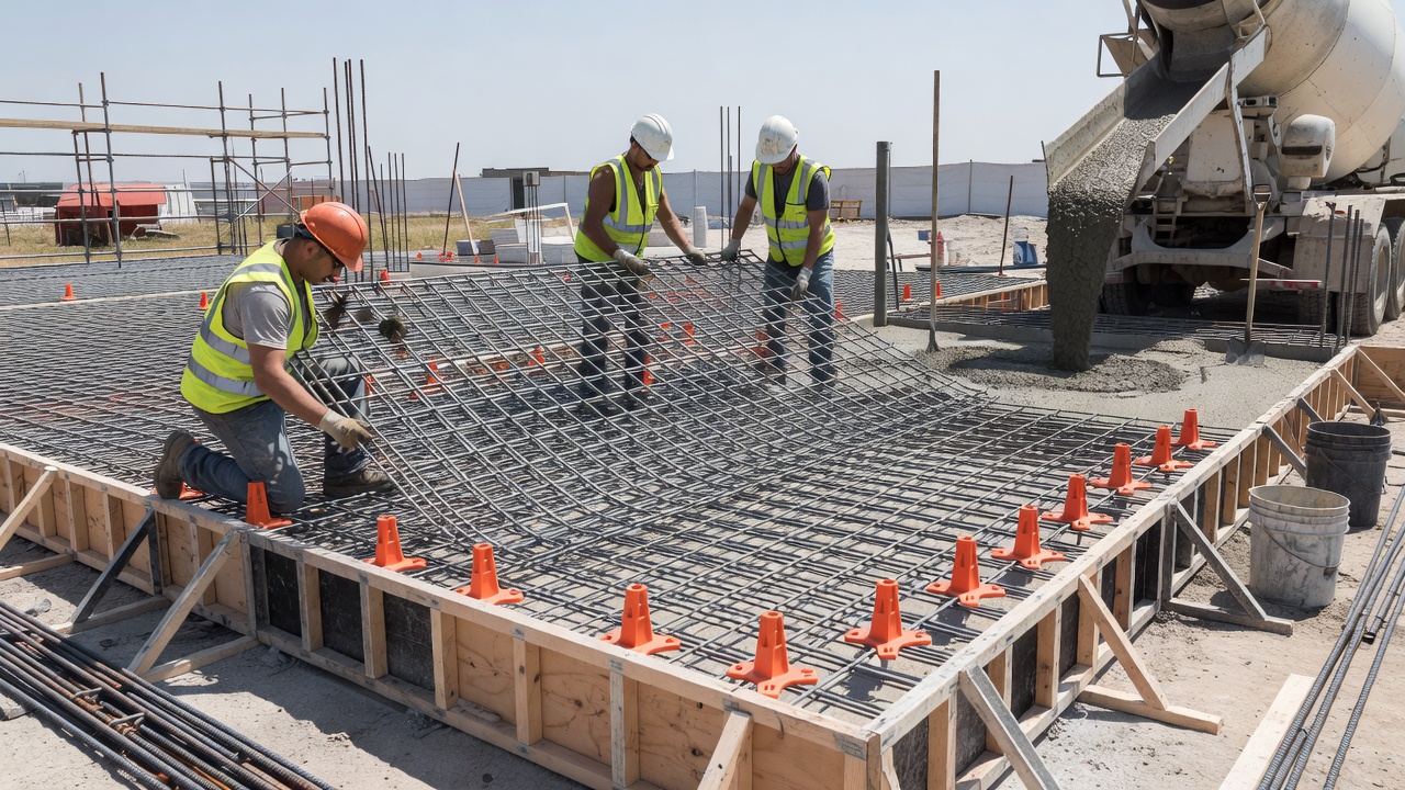
Installation Efficiency is where WWR offers its greatest advantage. A 20 ft. × 8 ft. WWR sheet can be positioned in minutes by a small crew, whereas an equivalent rebar mat with bars at 12 in. spacing would require cutting and tying approximately twenty longitudinal bars and eight transverse bars — a process taking significantly longer. Studies by the Wire Reinforcement Institute indicate that WWR can be placed at rates 2 to 4 times faster than hand-tied rebar, with corresponding reductions in field labor costs and construction schedules. This efficiency is most pronounced in large, flat work areas such as slabs-on-grade, pavements, and wall panels.
Mechanical Properties differ between the two products. WWR wires are cold-drawn, which produces a higher yield strength (typically 65 ksi to 80 ksi, with standard grades at 65 ksi and 75 ksi) compared to standard Grade 60 rebar (60 ksi minimum yield). The cold-working process also results in a stress-strain curve that lacks a distinct yield plateau — the transition from elastic to plastic behavior is more gradual. Rebar, being hot-rolled, exhibits a well-defined yield point and yield plateau. Despite these differences, both materials are considered “mild steel reinforcement” for design purposes under ACI 318 and can be used interchangeably in many applications when properly designed.
Diameter Range and Application Suitability is where rebar maintains a clear advantage. The largest standard WWR wire is W31 (D31 at 5/8 in. diameter), providing 0.31 in² per wire. A single #11 rebar provides 1.56 in² — approximately five times the area of the largest WWR wire. For heavily loaded structural members requiring large reinforcement areas — deep beams, columns, thick mat foundations — rebar is the only practical option. WWR excels in applications requiring moderate reinforcement ratios distributed over large surface areas: slabs, walls, pavements, and precast panels where the reinforcement area per unit width is the controlling parameter rather than the area per individual bar.
Applications of Welded Wire Reinforcement
Slabs-on-Grade represent the most common application for WWR in construction. In residential, commercial, and industrial floor slabs, WWR functions as temperature and shrinkage reinforcement per ACI 360 — controlling crack widths that result from the volume changes caused by concrete drying shrinkage and thermal fluctuations. The reinforcement does not prevent cracking but limits crack widths to acceptable levels (typically 0.01 in. to 0.02 in.) by providing tensile restraint across crack faces. For a typical 5 in. to 8 in. thick slab-on-grade, the reinforcement ratio (As / bh) is generally between 0.0018 and 0.0025 of the gross concrete area, as specified in ACI 318 Section 24.4 for shrinkage and temperature reinforcement. Standard WWR styles used in slabs include 6×6-W1.4×W1.4 (0.028 in²/ft), 6×6-W2.9×W2.9 (0.058 in²/ft), and 6×6-W4.0×W4.0 (0.080 in²/ft).
Pavements — both highway and airfield — use WWR extensively for crack control in jointed concrete pavements. In highway pavement, WWR is placed at mid-depth of the slab (typically 9 in. to 12 in. thick) to control temperature and shrinkage stresses between contraction joints. The wire provides dowel-like load transfer across cracks that may develop between saw-cut joints. For airfield pavements subject to heavy aircraft loads, heavier WWR styles such as 6×12-W12×W5 or 6×12-W16×W8 are specified. ICAO Annex 14 and FAA Advisory Circular 150/5320-6G provide guidance on pavement thickness design and reinforcement requirements for airport pavements. The FAA P-501 specification for Portland cement concrete pavement requires welded wire fabric to be flat and meet specified elevations within ±0.5 in. tolerances after fastening to chairs.
Walls — including retaining walls, tilt-up panels, basement walls, and shear walls — benefit from WWR ability to provide two-way reinforcement in a single placement operation. The pre-welded grid ensures that both the vertical and horizontal reinforcement are correctly positioned relative to each other, maintaining the required cover on both faces. For structural walls designed per ACI 318, WWR can satisfy both the minimum vertical and horizontal reinforcement ratio requirements (typically 0.0012 to 0.0020 of gross concrete area depending on wall thickness and reinforcement grade). The WWR Design and Detailing Guide published by the Wire Reinforcement Institute provides comprehensive design examples for shallow foundations, ground-supported slabs, tilt-up panels, cantilever retaining walls, and conventional two-way slabs.
Precast Concrete Products utilize WWR extensively. Concrete pipe, manholes, vaults, septic tanks, barrier walls, and precast bridge elements are commonly reinforced with WWR sheets or cages. The welded grid provides dimensional stability during concrete placement in forms, ensures consistent cover, and eliminates the labor of tying individual bars in repetitive production environments.
WWR Placement Requirements
Chair Supports are mandatory for proper WWR placement. Plastic or metal chairs (also called spacers, dobies, or bolsters) must be placed beneath the wire mesh at spacing intervals sufficient to prevent sagging or displacement during concrete placement. The Wire Reinforcement Institute recommends chair spacing not exceeding 36 inches for typical WWR styles used in slabs. Heavier WWR mats with larger wire diameters may permit wider spacing, while lighter mats with small wires require closer support. The chairs must have a height equal to the specified concrete cover — typically 2 inches from the bottom of the slab for WWR placed in the middle third or upper third of the slab thickness. Chairs should be placed on firm subgrade or vapor barrier to prevent them from sinking during concrete placement.
Support Systems for WWR must account for construction loads including the weight of workers, concrete buggies, and the concrete itself during placement. ACI 301 specifies that reinforcement supports must be designed to withstand these loads without displacement. For slabs-on-grade, common practice uses continuous ribbon-type supports (runner bars or continuous chairs) rather than individual spot chairs to provide greater stability. In pavement construction, wire chairs with broad bases are specified to prevent penetration into the subbase. The WWR sheets are tied to the chairs using tie wire at alternating intersections — typically every 3 ft. to 4 ft. along the support lines.
Lap Splicing requirements follow ACI 318 Section 25.5.4 for welded plain wire reinforcement and Section 25.5.5 for welded deformed wire reinforcement. For plain wire WWR, the minimum lap splice length is the greater of one full mesh spacing (one square) plus 2 inches or 6 inches, measured between the outermost cross wires of each sheet. For deformed wire WWR, the development length and lap splice requirements are calculated based on wire size, concrete strength, and cover conditions, similar to deformed rebar. The splice lengths for deformed wire range from approximately 12 inches to 48 inches depending on the wire diameter and concrete compressive strength. All lap splices must be positioned so that at least two cross wires of each sheet are engaged within the splice length. Adjacent lap splices in the same plane should be staggered by at least one full mesh spacing to avoid weak planes.
Concrete Cover requirements for WWR are specified in ACI 318 Chapter 20 and depend on the exposure conditions. For slabs not exposed to weather or in contact with ground: 0.75 in. minimum cover. For slabs exposed to weather: 1.5 in. minimum. For concrete cast against and permanently in contact with ground: 3 in. minimum. In pavement construction, the cover requirements are typically 2.0 in. ± 0.5 in. from the top surface and 2.0 in. ± 0.5 in. from the bottom surface, with the WWR positioned at mid-depth. The importance of maintaining specified cover cannot be overstated — insufficient top cover leads to corrosion of wires near the surface (spalling and rust staining), while excessive cover reduces the effective structural depth and crack control efficiency.
Common Defect: WWR at Bottom of Slab
The most frequently observed inspection finding in concrete slab construction is welded wire reinforcement found resting on the bottom of the slab — at the subgrade or vapor barrier interface — instead of in the specified upper-third or mid-depth position. This defect is so common that it has acquired colloquial names in the industry: “dropped mesh,” “stomped mesh,” or “bottom-of-slab mesh.” The fundamental problem is that mesh at the bottom of the slab provides virtually no crack control function because it is not positioned where tensile stresses develop — which is near the top surface for slabs-on-grade subject to shrinkage and temperature effects. ACI 360 states unequivocally that reinforcement in slabs-on-grade must be positioned in the upper half of the slab to be effective for crack control.
Root Causes of this defect are well-documented. The primary cause is the practice of placing WWR directly on the subgrade and then attempting to “hook” or “lift” the mesh into position as concrete is placed. Sufficient chairs or supports are often not installed, or chairs of inadequate height are used. Workers walking on the mesh during concrete placement depress it into the fresh concrete, pushing it downward toward the subgrade. The use of concrete buggies and power screeds operating on top of the mesh pushes the wires downward. In some cases, contractors cut corners by omitting chairs entirely, relying on the stiff concrete mix to hold the mesh in position — a practice that routinely fails.
Quantified Effectiveness Loss when WWR is at the slab bottom is dramatic. Structural analysis shows that WWR positioned at the bottom of a 6 in. slab provides only 10% to 20% of the crack control effectiveness of WWR positioned 2 in. below the top surface. This is because the tensile stress at the bottom of a slab-on-grade from shrinkage and thermal effects is near zero — the bottom of the slab goes into compression, not tension. The reinforcement must be in the tension zone to function. The American Society of Concrete Contractors identifies misplaced reinforcement as one of the top quality issues in concrete construction, with industry estimates suggesting that a significant percentage of slabs have WWR that has settled to or near the bottom of the slab.
Preventive Measures are straightforward but require enforcement. Chairs must be specified in contract documents and inspected before concrete placement. Support spacing should be detailed — typically no more than 36 in. on center. Continuous high chairs (also called “hog-rod” supports or “dobie strips”) are preferred over individual spot chairs for slab applications. During concrete placement, workers must use rolling bridges or runways to avoid walking directly on the mesh. The contractor should place concrete in a manner that minimizes disturbance to the reinforcement — depositing concrete at the face of the advancing pour rather than dumping it ahead of the pour and pushing it into place. Inspection before and during concrete placement is the most reliable control measure.
Inspection of WWR Position
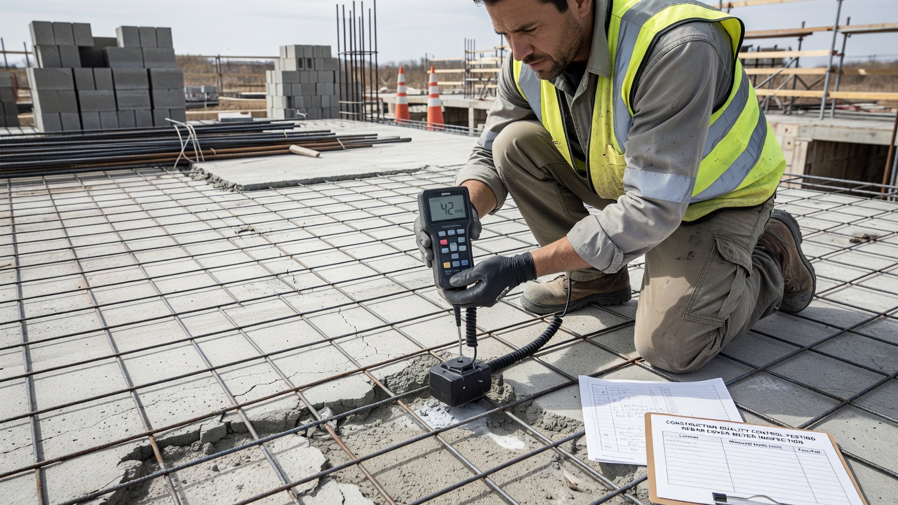
Cover Meters (Pachometers) are the primary nondestructive testing (NDT) tool for locating and measuring the depth of WWR in hardened concrete. These devices operate on the principle of electromagnetic pulse induction — a probe generates a magnetic field that interacts with the steel reinforcement, and the instrument measures the response to calculate the distance to the steel surface. Modern cover meters can detect individual wires in a WWR grid, map their position across a slab surface, and provide accurate cover depth measurements to within ±3 mm (±0.12 in.) when properly calibrated. Cover meter surveys should be conducted on a grid pattern — typically 5 ft. × 5 ft. or 10 ft. × 10 ft. — to build a statistically valid picture of wire position across the slab area.
Ground-Penetrating Radar (GPR) offers additional capability for WWR inspection, particularly for large pavement areas where rapid scanning is needed. GPR systems transmit high-frequency electromagnetic pulses (typically 1.0 GHz to 2.6 GHz frequencies for concrete investigation) into the slab and record the reflections from interfaces between materials with different dielectric properties — including steel reinforcement. GPR can detect not only the position of WWR but also the slab thickness, subbase condition, voids, and moisture content in a single pass. Modern GPR systems equipped with multi-channel antenna arrays can scan a 10 ft. wide lane in a single pass and produce real-time depth-section images showing the reinforcement grid. The primary limitation of GPR for WWR detection is the difficulty of distinguishing individual closely-spaced wires — the radar resolution may merge adjacent wires into a continuous reflection band.
Concrete Cores provide the definitive (destructive) method for verifying WWR position. A 4 in. or 6 in. diameter core extracted through the slab at selected locations reveals the actual position of the wire relative to the top and bottom surfaces, the concrete cover on both faces, the condition of the wire (corrosion), and the quality of the concrete surrounding the reinforcement. Core locations should be selected based on cover meter survey results — targeting areas showing unusually deep or shallow cover measurements. After extraction, the core is split or saw-cut longitudinally to expose a cross-section showing the wire embedded in the concrete matrix. The measured cover from the core can be compared against specified requirements and used to calibrate cover meter readings for the remainder of the slab.
Acceptance Criteria for WWR position are typically defined in project specifications. Common criteria include: WWR must be within the upper third of the slab thickness (for slabs-on-grade designed with reinforcement near the top), or within ±0.25 in. of the specified elevation (typically mid-depth for pavement slabs). A statistical sampling plan is used — for example, five cover meter readings per 1,000 sq. ft. of slab, with individual readings not deviating more than 0.5 in. from the specified cover, and 90% of readings within 0.25 in. of specification. Core samples are taken if cover meter readings indicate systematic deviation from specified position. FAA Advisory Circular 150/5320-6G specifies acceptance criteria for airfield pavement reinforcement positioning.
WWR Condition — Corrosion
Corrosion Mechanisms affecting WWR in concrete are fundamentally the same as those affecting rebar. In the highly alkaline concrete environment (pH 12.5 to 13.5), steel reinforcement is protected by a passive iron oxide film that forms on the steel surface. This passive layer prevents active corrosion. However, carbonation — the reaction of atmospheric carbon dioxide with calcium hydroxide in the concrete — progressively reduces the pH near the surface, eventually reaching levels (below pH 9) where the passive film breaks down and corrosion initiates. Chloride ingress from deicing salts, seawater, or chloride-containing admixtures is a more aggressive depassivation mechanism, causing localized pitting corrosion at chloride concentrations exceeding a threshold value (typically 0.2% to 0.4% chloride by weight of cement).
Corrosion of WWR manifests differently than rebar corrosion due to the smaller wire diameters. A W4 wire (0.225 in. diameter) loses a much larger proportion of its cross-sectional area to a given depth of corrosion penetration than a #4 rebar (0.500 in. diameter). A corrosion penetration of 0.03 in. (about the thickness of a credit card) reduces the W4 wire area by approximately 25% — severely compromising its tensile capacity. The same penetration depth on a #4 rebar causes only about 11% area loss. This makes WWR more vulnerable to corrosion-induced capacity loss than larger diameter rebar. Corrosion products (rust) occupy up to six times the volume of the original steel, generating expansive stresses that cause cracking and spalling of the concrete cover.
Protective Measures for WWR in corrosive environments include: increased concrete cover (per ACI 318, up to 3 in. for concrete exposed to deicing salts or in severe exposure), low water-cement ratio concrete (0.40 to 0.45 maximum), use of corrosion inhibitors, and protective coatings. Epoxy-coated WWR per ASTM A884 provides a fusion-bonded epoxy coating applied to the fabricated wire sheets. The coating acts as a physical barrier between the steel and the concrete environment. Epoxy-coated WWR is specified in bridge decks, parking structures, and marine exposure applications. Galvanized WWR (hot-dip galvanized per ASTM A123) provides sacrificial zinc coating protection. Stainless steel WWR is available for the most aggressive environments but at significantly higher cost.
Inspection for Corrosion during condition surveys should include: visual examination of exposed concrete surfaces for rust staining and cracking along wire lines, delamination sounding (chain drag or hammer sounding) to identify areas where corrosion-induced spalling has occurred, cover depth measurement to identify areas with inadequate cover, chloride content testing of concrete powder samples taken from the cover zone, half-cell potential mapping to identify actively corroding areas, and direct examination of the wire in extracted cores. Corrosion rate measurements using linear polarization resistance techniques can provide quantitative data on active corrosion rates.
WWR for Airport Slabs
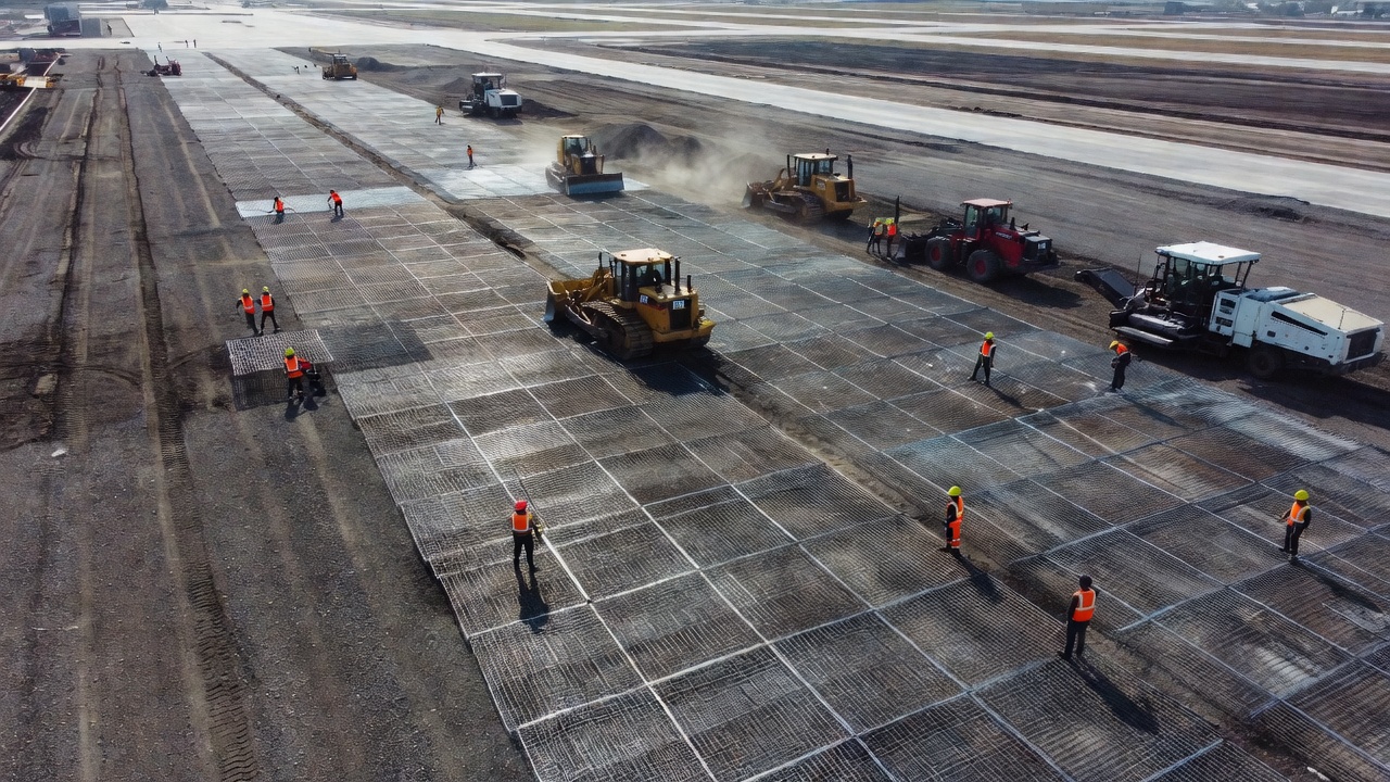
Airfield Pavement Requirements for WWR are more stringent than those for highway or commercial slabs. FAA Advisory Circular 150/5320-6G (Airport Pavement Design and Evaluation) and FAA P-501 (Portland Cement Concrete Pavement) provide detailed specifications for welded wire reinforcement in airfield pavements. The reinforcement is used primarily in jointed plain concrete pavement (JPCP) and jointed reinforced concrete pavement (JRCP) to control cracking and provide load transfer across cracks. ICAO Annex 14 Volume I (Aerodrome Design and Operations) references pavement design standards that incorporate reinforcement requirements through the national standards (FAA for US airports).
Reinforcement Design for airport pavements considers aircraft gear loads, subgrade strength, traffic volume, and slab dimensions. Slab thicknesses for airport pavements typically range from 10 in. to 20 in. depending on the aircraft classification number (ACN) and pavement design life. In jointed reinforced concrete pavements, WWR is positioned at mid-depth of the slab to control temperature and shrinkage stresses between contraction joints spaced at 15 ft. to 25 ft. intervals. The reinforcement ratio typically ranges from 0.1% to 0.3% of the gross concrete area in each direction, with larger ratios used for thicker slabs and wider joint spacing.
Typical WWR Styles specified for airport pavement include 6×12-W12×W5 (longitudinal wires at 6 in., 0.12 in²; transverse wires at 12 in., 0.05 in²) for medium-duty pavements and heavier styles such as 4×12-D16×D8 for heavy-duty airfield pavements handling wide-body aircraft including the Boeing 747, 777, and Airbus A380. The FAA standard specification requires that the maximum wire spacing does not exceed 12 in. in either direction and that the longitudinal wires (oriented parallel to the direction of traffic) have at least 50% more area than the transverse wires to account for the critical tensile stresses parallel to the aircraft travel direction.
Placement Tolerances are tightly controlled in airport construction. The WWR must be supported on chairs at spacing not exceeding 3 ft. in each direction, and the reinforcement mat must be flat within ±0.25 in. per 10 ft. in any direction. The specified cover from the top surface is typically 2.5 in. ± 0.5 in. for slabs up to 14 in. thick, and 3.0 in. ± 0.5 in. for thicker slabs. Inspection procedures for airport pavement reinforcement placement include: verification of chair spacing and height, cover measurements using cover meters on a grid pattern, and core samples at a frequency of one per 5,000 sq. yd. of pavement. The consequences of misplaced WWR in airport pavement are severe — premature cracking can lead to FOD (foreign object debris) generation from spalled concrete, creating significant safety hazards for aircraft operations.
Specifications Governing WWR
ASTM A1064/A1064M — Standard Specification for Carbon-Steel Wire and Welded Wire Reinforcement, Plain and Deformed, for Concrete — is the current governing material standard for WWR. Published initially in 2009, A1064 consolidated and replaced four former ASTM standards:
Former Standard
Scope
Date Withdrawn
ASTM A82/A82M
Steel wire, plain, for concrete reinforcement
Withdrawn, replaced by A1064
ASTM A185/A185M
Steel welded wire reinforcement, plain, for concrete
Withdrawn, replaced by A1064
ASTM A496/A496M
Steel wire, deformed, for concrete reinforcement
Withdrawn, replaced by A1064
ASTM A497/A497M
Steel welded wire reinforcement, deformed, for concrete
Withdrawn, replaced by A1064
The consolidation eliminated the need for multiple inter-referenced standards and simplified specification writing. A1064 covers material requirements (chemical composition, tensile strength, yield strength, bend test requirements), dimensional requirements (wire diameters, spacing tolerances, mat dimensions), weld shear strength requirements (minimum 35,000 psi average for plain wire, 45,000 psi for deformed wire), and deformation geometry requirements for deformed wires. The standard also defines the W/D wire size nomenclature and provides testing procedures.
ASTM A884/A884M — Standard Specification for Epoxy-Coated Steel Wire and Welded Wire Reinforcement — covers fusion-bonded epoxy-coated WWR for corrosion-resistant applications. The standard specifies coating thickness (7 to 17 mils), coating flexibility (bend test requirements), coating continuity (holiday detection), and repair procedures for damaged coating.
ASTM A123/A123M — Standard Specification for Zinc (Hot-Dip Galvanized) Coatings on Iron and Steel Products — covers galvanized WWR where sacrificial zinc protection is required.
Design Code References govern the structural application of WWR:
ACI 360 — Guide to Design of Slabs-on-Ground — provides design methodologies for WWR in slabs
ACI 350 — Environmental Engineering Concrete Structures — covers WWR in water and wastewater structures
FAA P-501 — Standard Specification for Portland Cement Concrete Pavement — covers WWR in airfield pavements
Comparison of WWR with Fiber Reinforcement
Fiber reinforcement — including polypropylene microfibers, macro synthetic fibers, and steel fibers — provides an alternative approach to crack control in concrete that differs fundamentally from WWR. Fibers are distributed uniformly throughout the concrete matrix in three dimensions, providing isotropic reinforcement at the microstructural level. WWR provides reinforcement in two planes (horizontal) at a specific elevation within the slab. Understanding the performance differences between these two systems is essential for appropriate specification.
Mechanism of Action differs significantly. WWR acts as crack-width control reinforcement — it does not prevent cracks from forming but restricts the width of cracks that do develop by providing concentrated tensile resistance across the crack plane. The reinforcement ratio and yield strength of the wires determine the maximum crack width that can be restrained. Fibers, particularly microfibers, act as crack prevention reinforcement — they intercept microcracks during the plastic and early hardening stages of concrete, reducing the formation of visible cracks at the surface. Macro synthetic and steel fibers provide post-crack ductility and residual flexural strength after cracking occurs.
Performance Comparison for typical slab applications:
Characteristic
Welded Wire Reinforcement
Fiber Reinforcement
Primary function
Crack width control
Microcrack prevention / toughness
Reinforcement orientation
2D planar (horizontal only)
3D isotropic (random)
Position dependency
Critical — must be in tension zone
Distributed throughout — no position sensitivity
Structural capacity
Yes — provides calculable tensile strength
Limited — fibers provide post-crack ductility
Crack width control at service load
Good — predictable and reliable
Variable — depends on fiber type and dosage
Placement sensitivity
High — chairs and support critical
None — added to mix
Corrosion risk
Steel — susceptible to corrosion
Polypropylene — corrosion-free
Design methodology
Established per ACI 318/360
Evolving — ACI 544, fiber manufacturers
Application for structural loads
Yes — designed reinforcement
No — not considered structural
Combined Use of WWR and fibers is common in many applications. Addition of synthetic microfibers at typical dosage rates of 1.0 to 1.5 lb per cubic yard provides plastic shrinkage crack reduction during the first few hours after placement, while the WWR provides long-term service-level crack control. In industrial floor slabs, the combination of WWR for structural reinforcement and steel fibers for toughness and impact resistance provides a robust solution for heavy loading conditions. The Concrete Reinforcing Steel Institute and Wire Reinforcement Institute both provide guidance on combined reinforcement systems.
Cost Comparison depends on project scale, labor rates, and material costs. WWR material cost is typically lower per pound than fibers, but the total installed cost of WWR must include chairs, tying wire, labor for placement, and inspection costs. Fiber reinforcement costs are fully contained in the material delivered to the mixer — no additional labor is required beyond mixing. For small residential slabs (up to 2,000 sq. ft.), fibers may be cost-competitive with WWR when all installation costs are considered. For large commercial or industrial projects, WWR typically provides more cost-effective reinforcement per unit of tensile capacity. The decision between WWR and fiber reinforcement should be based on structural requirements, exposure conditions, crack control objectives, and construction methodology — not solely on material cost comparisons.
Summary: Welded wire reinforcement remains a primary reinforcement material for concrete slabs-on-grade, pavements, walls, and a wide range of structural and non-structural applications. Its advantages in installation speed, consistent wire positioning, and predictable structural performance make it the preferred choice for engineers and contractors. The critical requirement for successful WWR performance is correct positioning within the slab — reinforcement found at the bottom of the slab due to inadequate support provides minimal crack control benefit. Proper specification of wire sizes and spacing per ASTM A1064, adequate chair support, and thorough inspection using cover meters, GPR, and cores ensure that WWR performs as intended for the design life of the structure.
Frequently Asked Questions
Welded wire reinforcement (WWR) is a prefabricated mesh grid of cold-drawn steel wires welded at intersections, while rebar consists of individual deformed steel bars placed and tied manually in the field. WWR offers faster installation rates, lighter weight, and more consistent wire spacing compared to hand-tied rebar mats. However, rebar provides larger bar diameters (up to #18 or 2.25 in.) and is more suitable for heavily loaded structural members like beams and columns where large reinforcing bar areas are required. Both are considered mild steel reinforcement and are designed per ACI 318 requirements.
For slabs-on-grade, WWR should be positioned within the upper third of the slab thickness, typically 2 inches below the finished surface for a 6-inch thick slab. This placement ensures the reinforcement is located where tensile stresses from shrinkage and temperature changes are highest. WWR must be supported on plastic or metal chairs (also called dobies or spacers) at spacing intervals typically not exceeding 36 inches to prevent displacement during concrete placement. A common construction defect is the mesh ending up at the bottom of the slab due to inadequate support and workers walking on it during concrete placement.
Typical common stock sizes for WWR include 6x6-W1.4xW1.4 (formerly 6x6-10/10), 6x6-W2.9xW2.9 (formerly 6x6-6/6), and 6x6-W4.0xW4.0 (formerly 6x6-4/4). The first two numbers indicate wire spacing in inches (longitudinal and transverse), while W followed by a number indicates the cross-sectional area of the wire in hundredths of a square inch. For example, W2.9 has a cross-sectional area of 0.029 in². Deformed wires use a D prefix instead of W.
WWR position in hardened concrete can be inspected using a cover meter (pachometer) which uses electromagnetic pulse induction to detect the depth and location of steel reinforcement. Ground-penetrating radar (GPR) can also be used to map the reinforcement grid across large pavement areas. For definitive verification, concrete cores can be extracted and visually inspected to measure actual cover depth and wire position. The most common finding in slab inspection is WWR found at the bottom of the slab instead of the specified upper-third position.
Fiber reinforcement (polypropylene or steel fibers) can replace WWR for shrinkage and temperature crack control in some non-structural slab-on-grade applications. However, fibers do not provide equivalent structural reinforcement because they lack the continuous, oriented tensile capacity of welded wire. Fibers work by bridging microcracks at a distributed level throughout the concrete matrix, while WWR provides concentrated tensile reinforcement at a specific plane. For structural applications requiring designed flexural capacity or where crack widths must be tightly controlled, WWR or rebar is required.
Expert Pavement Inspection Services
Need professional inspection of welded wire reinforcement placement in your concrete pavements? Our team uses advanced NDT methods including cover meters and GPR to verify WWR position and concrete cover.
Rebar is steel reinforcing bar embedded in concrete to carry tensile loads that concrete alone cannot resist. In infrastructure inspection, rebar condition is p...
A prestressing tendon is a high-strength steel element — typically seven-wire strand, wire, or bar — used in prestressed or post-tensioned concrete to apply per...
Tie bars are deformed steel bars placed across longitudinal joints in concrete pavement to prevent lane separation and hold adjacent slabs tightly together. Unl...
28 min read
Concrete Pavement
Joint Design
+3
Cookie Consent We use cookies to enhance your browsing experience and analyze our traffic. See our privacy policy.