Soil Nail Wall
Soil nailing is an in-situ ground reinforcement technique where closely spaced steel bars are grouted into a soil slope or excavation face as construction proce...
23 min read
structures
geotechnical
+4
Micropiles are small-diameter (typically 100-300 mm), drilled and grouted, high-strength deep foundation elements used for structural support, foundation underpinning, seismic retrofit, and slope stabilization in confined access areas and difficult ground conditions.
A micropile is a small-diameter, drilled, grouted, and reinforced deep foundation element that develops high axial capacity through the bond between the grout column and the surrounding ground. Per FHWA NHI-05-039, micropiles are defined as piles with a diameter of 300 mm (12 inches) or less, constructed by drilling a borehole, placing steel reinforcement inside, and grouting the hole. The term encompasses what are also called mini-piles, pin piles, needle piles, and root piles (palo radice). Originally developed in Italy in the 1950s by Dr. Fernando Lizzi, micropile technology was first used to underpin historic buildings damaged during World War II without the damaging vibration that driven piles would have transmitted into fragile masonry.
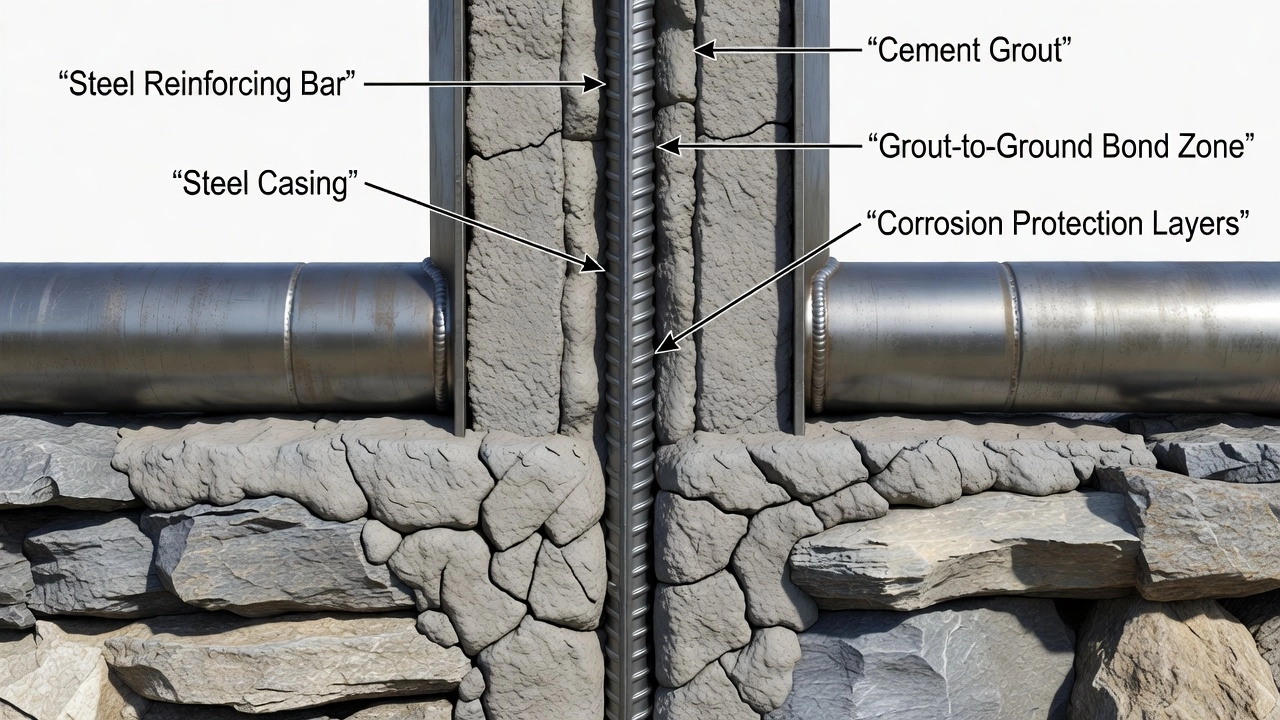
The three structural components of every micropile are the reinforcement (a high-strength threaded steel bar, permanent steel casing, or both), the grout body (neat cement grout typically with a water-cement ratio of 0.40 to 0.50), and the pile cap or structural connection that transfers load from the superstructure into the reinforcement. The reinforcement carries the axial load internally, the grout transfers the load from the reinforcement to the ground through skin friction along the bond zone, and the pile cap distributes the structural load into the group.
Micropiles are used across a broad range of applications. Foundation support for new structures where conventional deep foundations cannot be installed due to access constraints. Underpinning of existing foundations where settlement, increased load demand, or structural modification requires additional support. Seismic retrofit of bridges and buildings where existing foundations lack the capacity to resist earthquake demands. Slope stabilization where piles must transfer loads through a failure plane or potential shear zone. Excavation support as soldier piles in low-headroom Berlin Wall systems. Tall tower and wind turbine foundations where high single-element capacity is required from a small footprint. Bridge abutment and pier reinforcement where access beneath existing structures limits equipment size. Airport infrastructure supporting runway edge lights, navigation aids, and terminal expansions where vibration from driven piles must be avoided near sensitive electronics and existing aircraft operations.
FHWA and AASHTO LRFD Section 10.9 provide the regulatory framework for micropile design and construction in the United States. Internationally, EN 14199 (Execution of Special Geotechnical Work — Micropiles) governs European practice, while ICAO Annex 14 references deep foundation requirements for aerodrome structures through national building codes. The International Society for Micropiles (ISM), founded in 1997, maintains industry guidelines and publishes conference proceedings documenting global advances in micropile technology.
The Federal Highway Administration (FHWA) classifies micropiles into four distinct types based on the grouting method employed during construction. This classification directly governs the grout-to-ground bond capacity, which is the primary mechanism of load transfer for most micropile applications. The grouting method determines the degree of soil densification, fracture propagation, and radial stress development along the bond zone.
Type A — Gravity Grout. Grout is placed in the borehole under gravity head only, with no applied pressure. The borehole is typically drilled with casing that remains in place or is withdrawn after grout placement. Type A grouting is used predominantly in competent rock where the borehole remains stable and open, and where the rock mass already provides adequate bond capacity. The grout is a neat cement mixture with a water-cement ratio of 0.45 to 0.50, placed by tremie method from the bottom of the hole upward. Because no pressurization is applied, the grout does not penetrate cracks, fissures, or voids in the surrounding ground, and bond capacity depends entirely on the mechanical interlock between the grout column and the borehole wall. Type A micropiles typically develop the lowest bond capacities of the four types, with ultimate bond stresses in the range of 0.5 to 2.0 MPa (10 to 40 ksf) depending on rock type and quality.
Type B — Pressure Grouted Through Casing. After the drill casing is advanced to the design depth and the reinforcement is placed, neat cement grout is injected under controlled pressure through a pressure cap or grout head attached to the top of the casing. Typical grouting pressures range from 300 to 1,000 kPa (30 to 150 psi). The pressure is maintained as the casing is withdrawn incrementally, forcing the grout radially outward into the surrounding soil or rock. This pressurization densifies the soil immediately adjacent to the borehole, increases the effective confining stress on the grout column, and in granular soils, forces grout into intergranular voids, extending the load-transfer zone beyond the as-drilled borehole diameter. Type B micropiles are the most common configuration in US practice for mixed soil and rock profiles. Ultimate bond stresses typically range from 0.5 to 3.5 MPa (10 to 70 ksf) in granular soils and 1.0 to 5.0 MPa (20 to 100 ksf) in rock.
Type C — Single Global Post-Grout. Primary grout is placed by gravity or low pressure, typically using Type A or low-pressure Type B methods. After the primary grout reaches initial set (typically 4 to 12 hours), a single post-grouting pass is performed through a sleeved port pipe (also called a tube-à-manchette) installed along the bond zone. Grout is injected at high pressure (1,000 to 3,000+ kPa or 150 to 400+ psi) through a double-packer system that isolates individual ports. The high-pressure grout fractures the primary grout and surrounding ground, forming a network of grout veins that radiate outward from the borehole. This process substantially increases the effective diameter of the bond zone, improves the roughness of the grout-ground interface, and increases radial confining stress. Type C micropiles are used where high capacity is required from limited bond length, particularly in cohesionless soils where the grout fracturing mechanism is most effective. Ultimate bond stresses reach 1.0 to 5.0 MPa (20 to 100 ksf) in sands and 2.0 to 8.0 MPa (40 to 160 ksf) in rock.
Type D — Multi-Stage Post-Grout. The most aggressive grouting method consists of primary grout placement followed by two or more post-grouting passes through the sleeved port pipe system. Each successive pass uses higher pressure and is performed after the previous grout injection has set. The first post-grouting pass typically uses pressures of 1,000 to 2,000 kPa, the second pass 2,000 to 4,000 kPa, and subsequent passes up to 6,000 kPa (870 psi) or more. On each pass, the packer is positioned to inject grout through individual ports, progressively fracturing and re-fracturing the grout column and surrounding ground. This repeated pressurization creates a dense, highly interlocked grout mass with radial extensions up to several times the as-drilled borehole diameter. Type D micropiles develop the highest bond capacities of any micropile type, with ultimate bond stresses reaching 3.0 to 10.0+ MPa (60 to 200+ ksf) in competent rock. They are specified where extreme single-pile capacity is required, where bond zone length is severely limited by site constraints, or where the ground mass is variable and multi-stage grouting ensures uniform bond development.
| Grouting Type | Method | Typical Pressure | Typical Bond Stress | Primary Application |
|---|---|---|---|---|
| Type A | Gravity grout | 0 kPa (gravity) | 0.5-2.0 MPa | Competent rock, stable boreholes |
| Type B | Pressure through casing | 300-1,000 kPa | 0.5-3.5 MPa | Mixed soils and rock, standard US practice |
| Type C | Single post-grout | 1,000-3,000 kPa | 1.0-5.0 MPa | High capacity, cohesionless soils |
| Type D | Multi-stage post-grout | 1,000-6,000+ kPa | 3.0-10.0+ MPa | Extreme capacity, limited bond length |
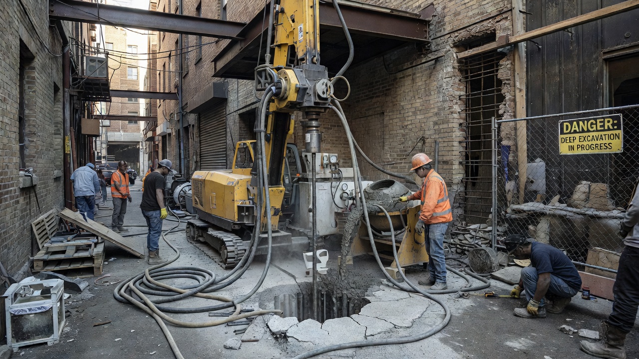
Micropile installation follows a sequenced drilling, reinforcement, and grouting process that varies depending on ground conditions, access constraints, and the specified grouting type. The installation equipment is smaller and more maneuverable than that required for conventional drilled shafts or driven piles, with low-headroom drill rigs capable of operating in spaces as tight as 2 meters (6 to 8 feet) of vertical clearance.
Step 1 — Drilling. A borehole is advanced through the overburden soils and into the competent bearing strata using rotary drilling, rotary-percussive drilling, or down-the-hole hammer techniques. The drilling method is selected based on the ground conditions: rotary drilling with roller-cone or drag bits for soft to medium ground, rotary-percussive with carbide-tipped button bits for hard rock and cobbles, and down-the-hole hammers for boulders and very hard rock. Temporary casing (typically 140 to 280 mm OD steel pipe) is advanced simultaneously with the drill bit through caving or collapsing soils to maintain an open borehole. In stable ground or rock, open-hole drilling without casing may be used. The borehole diameter is typically 50 to 100 mm larger than the permanent casing or reinforcing bar diameter to ensure adequate grout cover.
Step 2 — Cleaning. The borehole is cleaned of drill cuttings and debris using flushing with water, air, or drilling fluid (typically a bentonite-based or polymer-based drilling mud in unstable formations). The cleaning process is critical because residual cuttings at the grout-ground interface reduce bond capacity by interposing a low-strength layer between the grout and the natural ground. For Type C and D micropiles, thorough cleaning is even more important as the post-grouting process must be able to fracture the primary grout and penetrate the surrounding ground without obstruction from drilling debris.
Step 3 — Reinforcement Placement. A high-strength threaded steel bar is placed into the borehole, equipped with centralizers (typically at 2-3 meter spacing) to maintain the minimum specified grout cover around the bar. The centralizers ensure the bar is concentric within the borehole and prevent contact between the steel and the borehole wall, which would create a corrosion path and reduce bond capacity. The reinforcing bar is typically Grade 520 (75 ksi) or Grade 1035 (150 ksi) steel, with diameters from 25 mm to 75 mm. For cased micropiles, a permanent steel casing (Schedule 40 or 80 pipe) is installed over the non-bonded length (upper portion), with the reinforcing bar extending into the bond zone below the casing toe.
Step 4 — Grouting. Cement grout with a specified water-cement ratio of 0.40 to 0.50 is mixed in a high-shear colloidal mixer to ensure complete hydration and uniform consistency. The grout is placed by tremie method (a pipe extending to the toe of the borehole) from the bottom upward, displacing water or drilling fluid ahead of the grout front. For Type B micropiles, the grout pressure cap is attached to the top of the casing, grout is injected under pressure, and the casing is withdrawn incrementally as grout fills the annular space. For Type C and D micropiles, the sleeved port pipe is installed with the reinforcement, and post-grouting is performed after the primary grout has reached initial set. Each post-grout injection is recorded on a grouting log documenting pressure, volume, and location of each port injection.
Step 5 — Pile Cap Construction. After grouting is complete and the grout has reached the specified compressive strength (typically 28 MPa or 4,000 psi minimum), the pile head is prepared and the pile cap, grade beam, or structural bracket is constructed. The pile head is typically exposed by stripping the upper portion of the casing, the reinforcing bar is extended into the pile cap with a development length per AASHTO LRFD or ACI 318, and the cap reinforcement is tied to the exposed bar. The pile cap transfers the structural load into the micropile group and protects the pile head from corrosion and mechanical damage.
Micropiles transfer load to the ground through two primary mechanisms: skin friction along the bond zone (the predominant mechanism for most micropile installations) and end bearing at the pile toe (a secondary mechanism that is often neglected in design for conservative practice).
Skin friction (also called grout-ground bond or shaft resistance) develops along the interface between the grout column and the surrounding ground. The unit skin friction or bond stress (τ) is the shear stress mobilized at the grout-ground interface under applied load. The total skin friction capacity (Qs) is calculated as:
Qs = π × D × Lb × τavg
Where D is the effective borehole diameter, Lb is the bond zone length, and τavg is the average ultimate bond stress. The bond stress depends on ground type (rock type and quality, soil type and density), grouting method (Type A through D), borehole roughness (influenced by drilling method), and effective confining stress. FHWA NHI-05-039 provides bond stress design values for each grouting type and ground condition. In competent rock with Type D grouting, bond stresses of 5.0 to 10.0 MPa are routinely achieved. In loose sands with Type A grouting, bond stresses may be as low as 0.3 to 0.7 MPa.
End bearing develops at the pile toe through compression of the ground immediately beneath the micropile tip. However, because micropiles have a small cross-sectional area, end bearing contributes a relatively small portion of total capacity. A micropile with a 200 mm diameter drilled into rock with an unconfined compressive strength of 50 MPa would develop only 1,570 kN of end bearing capacity (assuming full mobilization), while the same pile with a 10-meter bond zone in the same rock could develop 10,000+ kN through skin friction. For this reason, most micropile designs neglect end bearing entirely and rely exclusively on skin friction, providing a built-in factor of safety.
Group effects must be considered when micropiles are installed in closely spaced groups. When the center-to-center spacing of micropiles is less than 3 pile diameters, the grout-ground bond zones of adjacent piles may overlap or interact, reducing the effective bond capacity per pile. The FHWA manual recommends calculating group efficiency using the Converse-Labarre equation or the Feld rule for micropile groups. Additionally, the structural capacity of the micropile itself must be checked, governed by the yield strength of the steel reinforcement, the compressive strength of the grout, and the combined section under axial and bending loads. The design capacity is the lesser of the geotechnical capacity (ground-controlled) and the structural capacity (steel-and-grout-controlled).
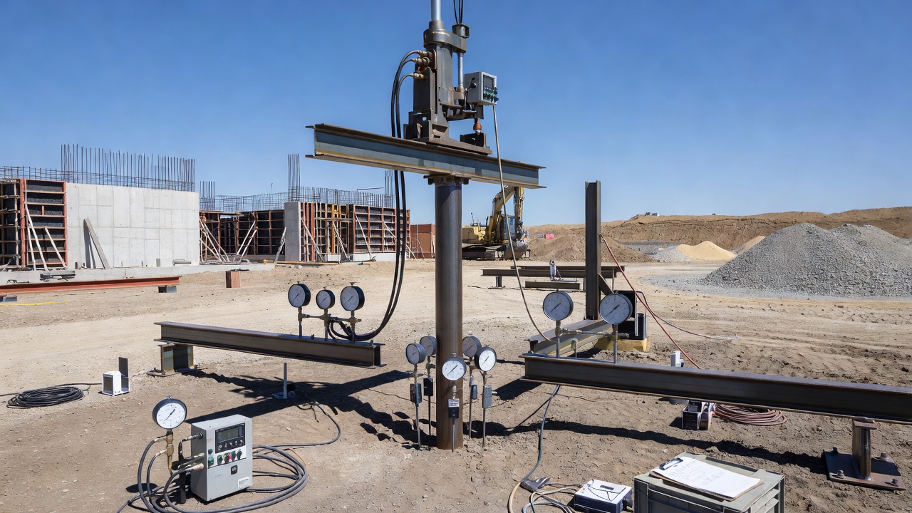
Load testing is mandatory for every micropile project per FHWA and AASHTO requirements, because the actual grout-ground bond capacity cannot be predicted with high precision from pre-construction soil investigations alone. Load tests verify that the as-built micropile achieves the design capacity and provide data to refine bond stress values for production pile installation.
Compression Load Testing (ASTM D1143). The standard method for testing micropiles under axial compressive load uses a hydraulic jack reacting against a weighted beam, anchored reaction frame, or a set of reaction piles. The test pile is instrumented with dial gauges, linear variable differential transformers (LVDTs), or electronic displacement transducers at the pile head and along the pile shaft (where telltale rods are installed). The load is applied in increments of 10 to 25 percent of the predicted ultimate capacity, with each increment held for a specified duration (typically 5 to 60 minutes) until the settlement rate stabilizes. The maximum test load is typically 200 to 250 percent of the design capacity for performance tests, or 150 percent for proof tests. The load-settlement data are plotted and interpreted using Davisson’s offset limit method, the Butler-Hoy method, or the Brinch-Hansen 90% criterion to determine the ultimate geotechnical capacity. The elastic shortening of the micropile is calculated from the steel and grout section properties and compared to the measured compression to verify load transfer behavior. If the measured settlement at design load exceeds the allowable (typically 12 to 25 mm depending on structure type), the bond zone length may need to be extended or the grouting method upgraded.
Tension (Uplift) Load Testing (ASTM D3689). Micropiles subjected to tensile or uplift loads (common in tower foundations, seismic retrofit anchors, and retaining wall tie-downs) are tested in tension using essentially the same reaction system as compression tests but with the jack positioned to pull the pile upward. The test setup includes a hydraulic jack acting against a reaction beam anchored at both ends. Displacement is measured at the pile head and, with telltales, at the tip. Tension capacity is typically 60 to 80 percent of the compression capacity for the same bond zone length, because the Poisson effect during tension reduces the radial confining stress at the grout-ground interface, lowering the available skin friction. The load-extension curve is analyzed similarly to compression tests, with the ultimate capacity determined from the intersection of the load-displacement curve with the elastic extension line offset by a specified displacement (typically 15 mm plus pile elastic extension).
Lateral Load Testing (ASTM D3966). For micropiles that must resist lateral loads from wind, earthquake, earth pressure, or braking forces on bridges, lateral load tests are performed using a hydraulic jack applying horizontal load at the pile head. The reaction is provided by an adjacent test pile, a reaction wall, or a heavy mass. Deflection is measured at the pile head and at multiple points along the pile shaft using inclinometer casing or string potentiometers. Lateral load capacity is governed by the bending stiffness (EI) of the micropile section, the soil stiffness in the upper strata, and the pile-head fixity condition (free, fixed, or partially restrained). The load-deflection curve is analyzed to determine the lateral subgrade reaction modulus (kh) using the p-y curve method per API RP 2A or AASHTO LRFD. For micropiles with permanent casing, the casing contributes significant bending stiffness compared to uncased bars alone.
Proof Testing vs. Performance Testing. Two types of load tests are distinguished in FHWA practice. Proof tests are conducted on approximately 5 to 10 percent of production piles (minimum one per structure) to verify that each individual pile meets the design criteria. Proof tests load to 150 percent of the design load. Performance tests are conducted on one or two sacrificial test piles per site, installed before production begins, to establish the ultimate geotechnical capacity of the micropile system. Performance tests load to 200 to 300 percent of the design load or to geotechnical failure. The results of performance tests are used to confirm the design bond stress values and, if capacity is higher than anticipated, to reduce production bond zone lengths.
Corrosion protection is a critical design consideration for micropiles because the small cross-sectional area of the steel reinforcement means that even modest corrosion loss substantially reduces structural capacity. A 50 mm diameter high-strength bar that loses 3 mm of section to corrosion loses approximately 12 percent of its cross-sectional area and corresponding axial capacity. FHWA, AASHTO LRFD Section 10.9, and EN 14199 specify corrosion protection requirements based on the aggressiveness of the ground environment and the consequence of pile failure.
Ground Environment Classification. The corrosion potential of the site is assessed by measuring soil resistivity, chloride ion concentration, sulfate concentration, pH, and the presence of stray electrical currents. AASHTO classifies ground environments as:
Single Corrosion Protection (SCP). Standard protection for non-aggressive environments consists of the cement grout cover over the reinforcing steel. The grout provides a highly alkaline environment (pH 12 to 13) that passivates the steel surface and inhibits corrosion. FHWA requires a minimum grout cover of 20 mm (0.75 inches) for permanent micropiles with SCP, with cover increased to 25 mm for aggressive environments. The grout must have a maximum water-cement ratio of 0.50 and minimum compressive strength of 28 MPa.
Double Corrosion Protection (DCP). For aggressive environments, the reinforcing bar is provided with a secondary barrier in addition to the grout cover. Typical DCP systems include:
Encapsulated Corrosion Protection (Full Encapsulation). For highly aggressive environments, marine exposures, or critical structures where corrosion-induced failure would have catastrophic consequences, the entire micropile is encapsulated in a corrugated PVC or HDPE sheath extending from the pile cap to the base of the bond zone. The annular space between the sheath and the ground is tremie-grouted, and the reinforcing bar inside the sheath is provided with DCP. The encapsulation provides a continuous physical barrier that isolates the steel and grout from the surrounding aggressive ground. The pile cap connection must also be encapsulated, with a watertight seal at the sheath-to-cap interface.
Cathodic Protection. In addition to passive corrosion protection, impressed current cathodic protection (ICCP) may be specified for micropiles in extremely aggressive environments (e.g., marine structures, industrial sites with stray currents). ICCP systems use a rectifier to apply a small electrical current through anodes installed adjacent to the pile group, polarizing the reinforcing steel to a potential at which corrosion is thermodynamically prevented. Regular monitoring of the protection potential per NACE SP0169 is required.
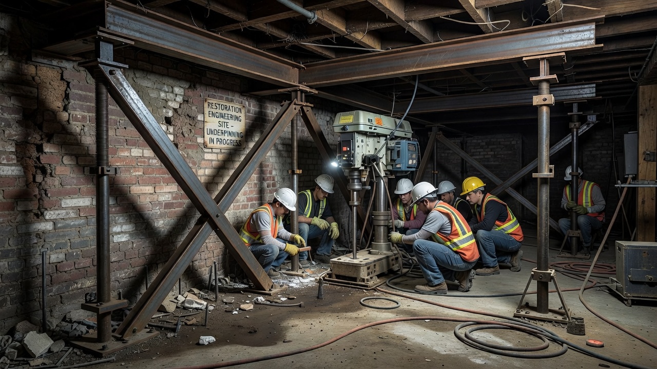
Underpinning is the process of strengthening or stabilizing an existing foundation by extending it to a deeper bearing stratum or increasing its load capacity. Micropiles are the most widely used deep foundation system for underpinning because of their low vibration, small equipment footprint, and ability to be installed directly adjacent to existing footings without undermining the existing support. The technique was pioneered by Dr. Fernando Lizzi in 1952 when he installed the first palo radice micropiles beneath the foundations of historic buildings in Italy.
Design Approach for Underpinning. The underpinning design must address three critical issues: (1) load transfer from the existing foundation to the micropiles, (2) load sharing between the existing foundation and the new micropile system during construction, and (3) differential settlement control. The existing foundation (typically a spread footing, strip footing, or mat) is either core-drilled to install the micropile directly through the footing, or the micropile is installed adjacent to the footing and connected via an underpinning bracket or needle beam. Direct coring through the footing is the most efficient method, creating a 150 to 300 mm diameter hole through the existing concrete, installing the micropile through the hole, and grouting the annular space between the pile and the existing concrete to achieve composite action.
Underpinning Sequence. The installation follows a strict sequence to prevent loss of support to the existing structure. For continuous footings, micropiles are installed in alternating pattern — every other pile position is completed first, then the intermediate positions are installed after the first set has achieved design capacity. The maximum unsupported span between completed piles is limited based on the existing footing’s flexural capacity and the soil support beneath it. For isolated column footings, the micropile group is installed around the perimeter of the existing footing, and a pile cap or grade beam is cast that encases the existing footing and the micropile heads. The load is transferred from the existing footing to the pile cap through shear friction and dowel bars drilled and epoxied into the existing concrete.
Settlement Monitoring. Underpinning projects require continuous settlement monitoring during installation. Optical survey targets, tiltmeters, and automated total stations are deployed on the existing structure at each column or load-bearing wall. The monitoring frequency during micropile drilling is typically hourly or per pile installed, with an alert threshold of 5 mm additional settlement and a stop-work threshold of 12 mm or the onset of visible cracking. Real-time monitoring data allows the contractor to adjust the installation sequence, grouting pressures, and construction rate to maintain structural stability.
Structural Connection. The connection between the underpinning micropile and the existing structure must develop the full design capacity of the pile. For direct-core installations, the bond between the new grout and the existing footing concrete must achieve a bond stress of at least 1.0 MPa over the depth of the footing. For bracket connections, the bracket is typically a structural steel assembly bolted or post-tensioned against the existing footing, with the micropile head bearing against the bracket base plate. The pile cap connection for adjacent piles uses a reinforced concrete cap that wraps around the existing footing, with reinforcing dowels drilled and bonded into the existing concrete at a grid spacing of 300 to 450 mm.
Micropiles are extensively specified for seismic retrofit of existing bridges, buildings, and infrastructure because they provide high axial and lateral capacity in a small footprint, can be installed adjacent to existing foundations without vibration, and can transfer loads through liquefiable soil layers to competent bearing strata. AASHTO and Caltrans seismic retrofit manuals include standard micropile connection details for bridge pier and abutment strengthening.
Liquefaction Mitigation. One of the most important seismic applications of micropiles is providing foundation support through liquefiable soils. During seismic shaking, saturated loose sands can lose shear strength and behave as a viscous liquid, causing driven piles and drilled shafts to lose lateral support and potentially buckle or undergo excessive deflection. Micropiles, because of their large length-to-diameter ratio and continuous grout body, maintain axial load capacity even when the surrounding soil liquefies, as long as the bond zone is developed in non-liquefiable strata below the liquefiable layer. The critical buckling load of the micropile through the liquefied zone is checked using the pile’s moment of inertia and the reduced (zero) lateral soil support. For this application, cased micropiles with permanent casing extending through the full depth of the liquefiable layer provide the highest buckling resistance.
Connection to Existing Structures. Seismic retrofit micropiles must be structurally connected to the existing foundation to develop full tension and compression capacity. The connection is typically a reinforced concrete pile cap or grade beam that is cast against the existing footing, pier, or abutment wall. The design must address: (1) dowel bar development — high-strength threaded bars or epoxy-grouted reinforcing dowels connecting the new cap to the existing concrete, (2) interface shear transfer — roughening the existing concrete surface and providing interface shear reinforcement per ACI 318, and (3) capacity protection — ensuring that the connection is stronger than the micropile so that inelastic behavior occurs in the pile (ductile steel) rather than the connection (brittle concrete).
Seismic Design Forces. The micropile and its connection are designed for the maximum considered earthquake (MCE) or design basis earthquake (DBE) per AASHTO LRFD Seismic Provisions. The design forces include: axial tension from structural overturning, axial compression from gravity plus seismic overturning, shear from the base shear at the foundation level, and moment from the fixity at the pile-cap connection. For micropiles in ductile behavior mode, the reinforcing bar is checked for strain compatibility under the seismic displacement demand, ensuring that the tensile strain in the bar does not exceed the ductility capacity of the steel (typically 6 to 12 percent elongation for Grade 520 steel, and 3 to 5 percent for Grade 1035 high-strength bars).
Inspection of micropile foundations includes during-construction quality control and in-service condition assessment of the visible structural elements — primarily the pile caps, grade beams, and pile head connections. Because the buried portion of the micropile cannot be directly inspected after installation, the load test record, grouting logs, and as-built documentation serve as the permanent quality record.
During-Construction Inspection. FHWA NHI-05-039 provides a comprehensive inspection checklist covering: pile location tolerance (typically ±75 mm from plan), plumbness (typically 1:50 maximum out-of-vertical), pile head elevation (within ±25 mm of plan), grout strength (minimum 7-day and 28-day compressive tests on grout cylinders), reinforcement bar size and grade verification, centralizer spacing and condition, casing thickness and grade, grout pressure and volume for each injection port, and post-grouting sequence compliance. All inspection data is recorded on daily installation logs that become part of the permanent project record.
Pile Cap and Connection Inspection. The pile cap is the only visible element of the micropile foundation system and must be inspected periodically for signs of distress. Key inspection items include:
AASHTO Condition State Rating. The AASHTO Manual for Bridge Element Inspection provides condition state ratings for pile caps (Element 212 — Pile Cap/Footing). The four condition states are:
Nondestructive Testing. Advanced inspection techniques for micropile caps include: ground-penetrating radar (GPR) to locate reinforcement and evaluate grout integrity within the cap, impact-echo testing to detect delamination and subsurface voids, ultrasonic pulse velocity to assess concrete quality and uniformity, half-cell potential mapping to identify active corrosion zones, and cover meter surveys to verify that reinforcement cover meets the specified minimum (typically 75 mm for cast-in-place caps).
Airport Applications. Micropiles are used at airports for foundation support of navigation aids (ILS localizer and glideslope antennas, approach lighting systems), radar towers, terminal expansions, hangars, and bridge structures within the airfield. The key advantage at airports is the restriction on vibration from construction — driven piles generate ground vibration that can damage sensitive electronic equipment, disrupt aircraft navigation systems, and disturb pavements. ICAO Annex 14 and FAA Advisory Circular 150/5370-10F specify allowable construction vibration limits for work near operational pavements. Micropiles, installed by drilling rather than driving, generate minimal ground vibration (typically < 2 mm/s peak particle velocity at 5 meters) and can be installed within a few meters of active runways and taxiways without disrupting operations. At airport bridge structures — bridges carrying taxiways over roadways, or roadways over taxiways — micropiles are specified for abutment and pier foundations where headroom is limited by the bridge deck and where the presence of underground utilities precludes driven pile installation.
Bridge Applications. Micropiles are used for new bridge foundations where access is constrained (urban interchanges, flyover ramps, bridges over water with limited barge access), for bridge widening and rehabilitation where existing footings must be extended without demolition, for scour repair where bridge foundations have been undermined by water flow and new deep support is needed, and for seismic retrofit where existing bridge piers must be strengthened to meet current code requirements. The FHWA Every Day Counts (EDC) program promotes micropiles as an accelerated bridge construction (ABC) technique because they can be installed rapidly with smaller equipment than drilled shafts, reducing the construction duration and traffic disruption.
FHWA and ICAO Regulatory References. The primary regulatory documents governing micropile use in transportation infrastructure are:
Cost and Production Considerations. For typical bridge foundation applications, micropile production rates range from 4 to 12 piles per day per drill rig, depending on ground conditions, pile depth, and grouting type. The installed cost per pile is typically $100 to $300 per linear foot depending on diameter, reinforcement, casing, corrosion protection, and site access constraints. This compares to $40 to $100 per linear foot for driven piles and $80 to $250 per linear foot for drilled shafts in equivalent conditions. The higher unit cost of micropiles is offset by the reduced mobilization requirements, smaller equipment footprint, ability to work in confined spaces, and elimination of vibration-related restrictions.
The long-term performance of a micropile foundation system depends on the integrity of the buried load-transfer elements (which cannot be directly inspected after construction) and the visible condition of the pile caps and connections (which must be inspected periodically). The critical inspection items that signal potential foundation distress include:
Visual inspection combined with nondestructive testing, load test record review, and corrosion assessment provides a comprehensive condition evaluation. TarmacView’s computer vision and aerial inspection solutions enable efficient, repeatable, and documented condition assessment of micropile caps, connections, and adjacent structural elements, supporting the bridge and airport infrastructure inspection programs required by ICAO Annex 14, FAA Advisory Circulars, and AASHTO Bridge Element Inspection Manuals.
TarmacView provides AI-powered visual inspection solutions for deep foundation elements including micropile caps, connections, and corrosion assessment. Schedule a demo to learn how aerial imagery and computer vision can streamline your foundation inspection workflow.
Soil nailing is an in-situ ground reinforcement technique where closely spaced steel bars are grouted into a soil slope or excavation face as construction proce...
Crosshole Sonic Logging (CSL) is an ultrasonic non-destructive testing method for evaluating the integrity of drilled shafts, bored piles, and slurry walls by t...
Cementitious grouting uses fluid cement-based mixtures poured or pumped to fill cracks, voids, or spaces in concrete — including tendon duct grouting, crack inj...