What is Microsurfacing?
Microsurfacing – Polymer-Modified Cold-Mix Surface Treatment for Pavement Preservation
Microsurfacing is a high-performance, cold-applied surface treatment system that combines polymer-modified emulsified asphalt, high-quality crushed mineral aggregate, mineral fillers, water, and field control additives. Unlike conventional slurry seal systems that rely on water evaporation for curing, microsurfacing uses a controlled chemical break mechanism, triggered by the interaction between the cationic emulsion and the mineral filler, that allows the mixture to set and cure rapidly without dependence on ambient temperature or solar radiation. This unique characteristic makes microsurfacing a versatile pavement preservation tool suitable for high-traffic roads, airport runways, taxiways, aprons, and other airfield pavements where rapid return to service and long-term durability are essential.
Definition and Distinction from Slurry Seal
Microsurfacing belongs to the family of slurry surfacing systems, which also includes conventional slurry seal, but differs in several fundamental ways that impact performance, application methodology, and suitable use cases. The International Slurry Surfacing Association (ISSA) defines microsurfacing as a mixture of polymer-modified cationic emulsified asphalt, 100 percent crushed mineral aggregate, mineral filler, water, and additives, proportioned, mixed, and uniformly spread over a properly prepared surface. The cured microsurfacing produces a dense, stable, skid-resistant mat that bonds firmly to the existing pavement.
The critical distinction between microsurfacing and slurry seal lies in the chemical curing mechanism. Slurry seal hardens through evaporation of water from the asphalt emulsion, a process that depends on ambient temperature, humidity, wind speed, and solar radiation. This limits slurry seal application to warm, dry conditions and makes it unsuitable for shaded areas, cool climates, or seasons with high humidity. Microsurfacing, by contrast, uses chemical destabilization of the emulsion through the addition of mineral fillers such as Portland cement or hydrated lime, which triggers a rapid break and sets the mixture within 15 to 30 minutes regardless of weather conditions. This chemical break mechanism allows microsurfacing to be applied in marginal weather, on shaded roadways, and in cooler temperatures that would prevent successful slurry seal placement.
Additional differences include the mandatory inclusion of polymer modification in the emulsion for microsurfacing (minimum 3% polymer solids by weight of residual asphalt), the requirement for 100 percent crushed aggregate with higher angularity and strength, and the ability to apply microsurfacing in variable thicknesses, including multi-layer construction up to 38 mm depth for rut filling. Slurry seal is typically limited to single-layer applications at 1 to 1.5 times the maximum aggregate size thickness and is not designed for structural correction of surface deformations. The cost of microsurfacing is approximately 30 to 50 percent higher than slurry seal, but its extended service life, faster traffic return, and rut-filling capability justify the premium for higher-traffic applications.
| Property | Slurry Seal | Microsurfacing |
|---|---|---|
| Emulsion type | Cationic slow-set (CSS-1, CSS-1h) | Polymer-modified CQS-1h (minimum 3% polymer) |
| Curing mechanism | Water evaporation (slow, weather-dependent) | Chemical break (fast, weather-independent) |
| Aggregate requirement | Conventional crushed/semi-crushed | 100% crushed, high-quality (granite, slag, traprock) |
| Maximum single-layer thickness | 6-10 mm (~1.5x aggregate top size) | 10-15 mm (can be built up in multiple passes) |
| Rut-filling capability | Not recommended | Yes, up to 38 mm in multiple layers |
| Traffic return time | 1-4 hours (slower in cool/damp conditions) | Within 1 hour (15-30 minutes typical) |
| Polymer requirement | Optional | Mandatory (minimum 3% by weight of bitumen) |
| Typical service life | 3-5 years | 5-7 years (up to 10 years on good pavements) |
| Suitable traffic levels | Low to medium (residential, secondary) | Medium to very high (arterials, highways, airports) |
Materials: Polymer-Modified Emulsion, Crushed Aggregate, and Additives
The performance of a microsurfacing system depends on the quality and compatibility of its constituent materials, the polymer-modified asphalt emulsion, the mineral aggregate, the mineral filler, and the various chemical additives used to control setting time and workability. Each component must meet the specifications defined in ISSA A143, ASTM D6372, and AASHTO MP 31 to ensure a durable, long-lasting treatment.
Polymer-Modified Emulsified Asphalt. The emulsion used in microsurfacing is a cationic quick-set grade designated CQS-1h per AASHTO M 208 or ASTM D 2397, with additional polymer modification. The polymer, typically styrene-butadiene-styrene (SBS), styrene-butadiene rubber (SBR), or ethylene-vinyl acetate (EVA), is milled or blended into the base asphalt or the emulsifier solution before the emulsification process. The polymer content must be a minimum of 3% polymer solids by weight of residual asphalt, although many high-performance systems use 5% or higher. The polymer modification improves cohesion and elasticity, increases resistance to rutting and cracking, enhances adhesion to the existing pavement, and extends the temperature range over which the material performs effectively. After distillation, the emulsion residue must have a softening point of minimum 57°C (ring-and-ball apparatus), a penetration range of 40 to 90 dmm at 25°C, and a minimum residue of 62% by weight of emulsion. The emulsion must exhibit less than 1% settlement and storage stability over 24 hours.
Mineral Aggregate. The aggregate component constitutes 85 to 93 percent of the cured microsurfacing by weight and must be 100 percent crushed from parent rock larger than the largest stone in the gradation. Suitable rock types include granite, traprock (basalt/diabase), quartzite, blast furnace slag, limestone, and other high-quality, abrasion-resistant materials. The aggregate must have a Los Angeles abrasion loss of maximum 30% (ASTM C131), a soundness loss of maximum 15% using sodium sulfate or maximum 20% using magnesium sulfate (ASTM C88), and the crushed particles must have two or more fractured faces at a minimum rate of 50% for Type II or 75% for Type III gradations. ISSA A143 defines two primary aggregate gradation bands:
| Sieve Size | Type II (Standard) | Type III (Heavy-Duty) |
|---|---|---|
| 9.5 mm (3/8") | 100 | 100 |
| 4.75 mm (No. 4) | 90-100 | 70-90 |
| 2.36 mm (No. 8) | 65-90 | 45-70 |
| 1.18 mm (No. 16) | 45-70 | 28-50 |
| 600 µm (No. 30) | 30-50 | 19-34 |
| 300 µm (No. 50) | 18-30 | 12-25 |
| 150 µm (No. 100) | 10-21 | 7-18 |
| 75 µm (No. 200) | 5-15 | 5-15 |
Type II aggregate uses a finer gradation and is suited for standard microsurfacing applications such as surface sealing, friction restoration, and light rut filling. Type III uses a coarser gradation that provides a more open texture, greater stone-on-stone contact, and higher resistance to shear stresses, making it the preferred choice for heavy traffic areas, deep rut filling, and high-stress applications including airport pavements.
Mineral Filler and Chemical Additives. The mineral filler, typically Portland cement (Type I or Type I/II), hydrated lime, or ground limestone, serves multiple critical functions: it accelerates the chemical break of the emulsion, controls the setting rate, improves the cohesion of the mixture, and fills the voids between aggregate particles. The filler content typically ranges from 0.5% to 3.0% by weight of dry aggregate, with the specific dosage adjusted during mix design to achieve the target set time and cohesion development. Chemical additives such as break control agents (retarders or accelerators) may be added at the time of mixing to fine-tune the setting behavior based on field conditions, temperature, humidity, aggregate moisture content, and wind speed. Aluminum sulfate or similar compounds may be used as accelerators, while certain phosphates or lignosulfonates serve as retarders.
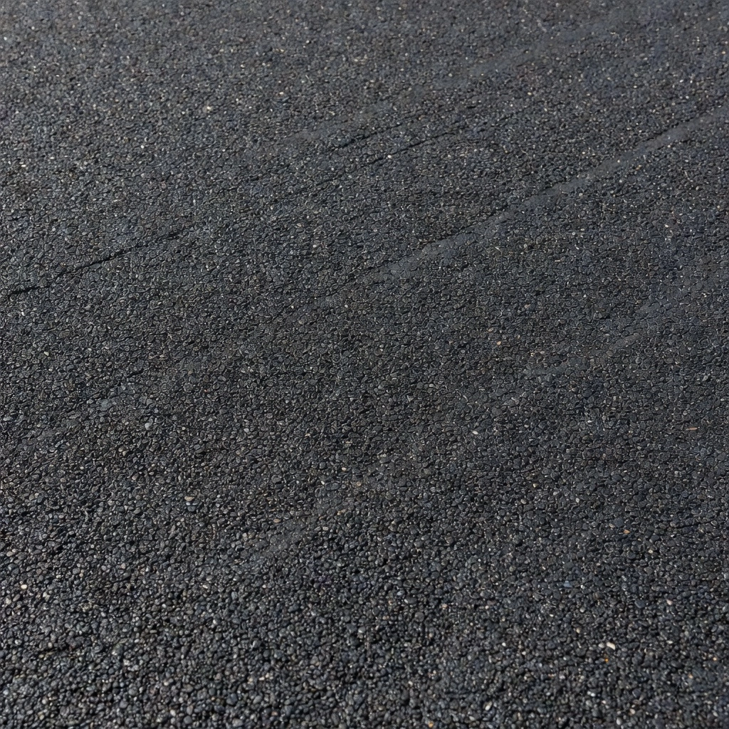
Mix Design per ISSA A143
The mix design for microsurfacing is performed according to ISSA A143 (Recommended Performance Guidelines for Micro Surfacing) , the definitive industry standard that defines the test methods, target values, and acceptance criteria for qualifying a microsurfacing system. A complete mix design evaluates the compatibility of the emulsion, aggregate, filler, and additives, and verifies that the optimized mixture meets minimum performance thresholds in six key laboratory tests.
Cohesion Testing (ISSA TB 139). This test measures the rate of strength gain of the microsurfacing mixture over time, simulating the curing process under controlled temperature conditions. The test uses a cohesion tester that applies a torque to a rubber foot pressed against the surface of a compacted specimen. The minimum requirements are 12 in-lbs (1.4 N·m) at 30 minutes and 23 in-lbs (2.6 N·m) at 60 minutes. These values ensure that the surface can support traffic loads within one hour of placement without ravelling or displacement.
Wet Track Abrasion Loss (ISSA TB 100 / ASTM D3910). This test determines the resistance of the cured microsurfacing to abrasion by water and traffic. A weighed specimen is soaked in water for 72 hours, then subjected to abrasion by a rubber hose rotating against the surface for 5 minutes. The maximum allowable abrasion loss is 807 g/m² (75 g/ft²) for Type II gradation and 538 g/m² (50 g/ft²) for Type III gradation at 6 days of cure. Lower values indicate a more durable, water-resistant surface.
Excess Asphalt Determination by Loaded Wheel Sand Adhesion (ISSA TB 109). This test detects the tendency of the cured mixture to flush or bleed excess binder to the surface. A loaded wheel (57 lb / 25.9 kg) applies 1,000 cycles of rolling load over a compacted specimen covered with standard sand. The maximum allowable sand adhesion is 538 g/m² (50 g/ft²) . Higher values indicate excess asphalt in the mixture, which can lead to surface flushing, reduced friction, and tracking under aircraft or vehicle tires.
Mix Time Test (ISSA TB 113). This field-simulated test determines the workable life of the mixture from the point of mixing to the loss of workability (when the mixture becomes too stiff to spread uniformly). The minimum mix time is 120 seconds at the designated field temperature. Inadequate mix time leads to premature breaking in the spreader box, poor surface finish, and construction defects.
Vertical and Lateral Displacement (ISSA TB 147). This test evaluates the stability of the microsurfacing mixture under simulated traffic loads. A compacted specimen is subjected to 1,000 cycles of a loaded rubber wheel, and the vertical deformation is measured. The maximum allowable vertical displacement is 5% of the specimen thickness. This is particularly critical for rut-filling applications where the mixture must resist re-deformation under traffic.
Classification Test (ISSA TB 144). This test determines whether the microsurfacing system classifies as standard or quick-set (QS) based on the cohesion development and mix time characteristics. Most airport and high-traffic applications require a QS (quick-set) classification, indicating that the mixture reaches minimum cohesion of 12 in-lbs within 30 minutes and supports traffic within 60 minutes.
The mix design process also establishes the optimum emulsion content (typically 8.5% to 13.0% by weight of dry aggregate), the filler dosage (0.5% to 3.0%), and the water content (to achieve target workability). All quantities are expressed as percentages by weight of dry aggregate. The job mix formula defines the target values for each component and the acceptable production tolerances, typically ±0.5% for emulsion content, ±0.5% for water, and gradation tolerances for each individual sieve as specified in ISSA A143.
Application Equipment: Continuous Pavers and Microsurfacing Machines
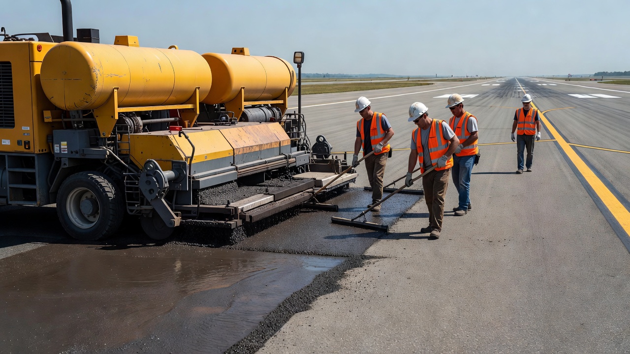
Microsurfacing is produced and placed using specialized equipment that combines the functions of material storage, proportioning, mixing, and application into a single self-propelled unit. Two equipment configurations are used depending on project scale and geometry: self-contained slurry trucks for smaller or segmented projects, and continuous mix-pavers for large-scale, high-production work.
Slurry Trucks (Self-Contained). A conventional slurry truck carries individual compartments for aggregate, emulsion, water, and filler, with a capacity typically ranging from 8 to 15 tonnes of aggregate. The materials are metered by calibrated belt feeders, positive displacement pumps, and variable-speed augers into a pugmill mixer mounted on the rear of the truck. The mixed material discharges into a spreader box (micro box) that is towed behind the truck. The spreader box contains horizontal augers that distribute the mixture evenly across the application width (typically 2.5 to 3.7 meters), and adjustable screeds or strike-offs control the application depth. Slurry trucks are self-contained for the duration of their load, once the aggregate or emulsion is exhausted, the truck must return to a reload point, creating a transverse construction joint. These joints are the most common source of surface irregularities in microsurfacing and must be managed carefully by overlapping or feathering the edges.
Continuous Mix-Pavers. For projects requiring long, uninterrupted stretches of surface treatment, typical of airport runways, taxiways, and major highways, continuous paving machines (also called continuous-run pavers or feedbox machines) are used. These machines anchor the productivity advantage of microsurfacing for large-scale work. A continuous paver has larger storage capacities for emulsion and water and is designed to receive continuous supplies of aggregate via a conveyor or belly-dump truck that drives alongside or ahead of the paver. Emulsion tankers and water trucks replenish the machine while it is in motion, allowing the paver to operate without stopping for reloading. The result is a jointless surface with no transverse construction seams, a critical advantage for airport pavements where surface evenness and smoothness are paramount.
The continuous paver carries three spreader boxes or interchangeable micro boxes in some configurations: a rut-filling box (narrow, deep, with confined augers for depositing material into wheel paths), a leveling box (for scratch courses on uneven surfaces), and a standard micro box (for the final surface course). The machine operator controls the application rate, the emulsion-to-aggregate ratio, the filler feed, and the water content from a central control panel. Application speeds range from 3 to 10 meters per minute depending on the layer thickness and project specifications.
Calibration and Quality Control. Before production begins, the equipment must be fully calibrated in accordance with ISSA A143 requirements. Calibration ensures that the metered quantities of aggregate, emulsion, water, and filler delivered during production match the job mix formula. The calibration procedure involves run-time measurement of each material stream, typically by weighing the aggregate output over a timed interval, measuring emulsion pump output against pump revolutions, and checking filler feeder rates. A calibration check must be performed at the start of each project, after any change in material source, and periodically during production (typically once per shift).
Rut Filling Capability
One of the defining capabilities of microsurfacing, and the primary reason it was originally developed in Germany during the late 1960s and early 1970s, is its ability to fill wheel-path ruts without the need for structural mill-and-fill operations. This capability is particularly valuable for preserving pavement cross-section and surface water drainage, and it is the feature that most clearly distinguishes microsurfacing from conventional slurry seal systems.
Ruts form in asphalt pavements as a result of consolidation (densification of the pavement layers under traffic) and plastic flow (lateral movement of the asphalt mixture under shear stress). Rut depths up to 12 mm can typically be corrected in a single pass of microsurfacing, while ruts from 12 to 38 mm require multiple applications. The standard practice for rut filling uses a rut-filling spreader box or a modified micro box that confines the mix within the wheel path by means of side plates or a narrow box width matching the rut width. The material is struck off at a controlled depth, slightly overfilling the rut to account for traffic consolidation.
The rut-filling procedure typically involves three sequential steps:
- Rut fill pass, Microsurfacing is applied directly into the wheel paths using a rut box, filling the depression to slightly above the surrounding pavement surface. The material is placed at a thicker cross-section within the rut, feathering to zero thickness at the edges.
- Leveling or scratch course (if needed), A full-width pass of microsurfacing at a uniform thickness (typically 5-8 mm) is applied to smooth the surface profile after the rut fill has cured.
- Final surface course, A full-width wearing course of microsurfacing (typically 8-12 mm thick) provides the finished skid-resistant surface and seals the entire pavement area.
Multiple agencies report successful correction of rut depths up to 38 mm (1.5 inches) using this layered approach. The polymer-modified binder and high-quality crushed aggregate provide the structural stability needed to resist re-deformation under traffic, a critical distinction from slurry seal, which would flow back into the rut under load. The loaded wheel displacement test (ISSA TB 147) during mix design verifies that the microsurfacing mixture will maintain its shape under traffic loading.
For airport pavements, rut correction by microsurfacing is applicable to taxiways, aprons, and service roads where rut depths are moderate and the underlying pavement structure is sound. Deep ruts (greater than 38 mm) or ruts accompanied by structural cracking should be investigated for underlying structural deficiencies before microsurfacing is applied as a corrective treatment. In those cases, the rut correction may be a temporary solution and the rutting may reappear unless the root cause, overloading, weak subgrade, or asphalt mix instability, is addressed.
Quick Traffic Return and Operational Advantages
The rapid curing of microsurfacing delivers one of its most significant operational benefits: traffic return within one hour of application. The chemical break mechanism triggers a rapid set that allows the surface to accept rolling traffic (straight-line movement) within 15 to 30 minutes under favorable conditions and within 60 minutes for stop-and-go traffic or turning movements. This rapid traffic return is a decisive advantage for high-traffic roads, urban intersections, and aircraft operating areas where extended lane or pavement closures cause costly delays.
The curing process proceeds in three stages. Stage 1, Mixing and Placement: The mixture is fluid and workable for a controlled period (minimum 120 seconds mix time per ISSA TB 113). During this stage, the material spreads and levels under the spreader box. Stage 2, Initial Break and Set: The water in the emulsion begins to separate from the asphalt as the chemical destabilization reaction progresses. The mixture changes from brown to black as the asphalt coats the aggregate, and the surface develops sufficient cohesion to resist displacement under light foot traffic. This stage typically occurs within 15 to 30 minutes. Stage 3, Final Cure and Consolidation: The surface achieves full cohesion (minimum 23 in-lbs at 60 minutes per ISSA TB 139) and can accept rolling traffic loads. Additional curing and consolidation continue over the first 24 to 72 hours as residual moisture evaporates and traffic further compacts and densifies the surface.
For airport environments, the rapid traffic return window means that runway and taxiway closures can be scheduled during nighttime maintenance windows or between peak traffic periods, minimizing disruption to flight operations. The Kentucky Transportation Cabinet’s first airport microsurfacing application at Capital City Airport (Frankfort, Kentucky) in 2019 demonstrated that a complete taxiway and runway overlay could be completed and returned to service within a single weekend closure, a timeline unattainable with hot-mix asphalt overlays requiring compaction, cooling, and extended cure.
Additional operational advantages of microsurfacing include:
- No heating required: The entire process is performed with cold materials. No hot-mix plant, fuel for heating, or temperature control at the point of placement is needed.
- Low emissions: As a cold-mix system, microsurfacing generates no volatile organic compounds (VOCs) or greenhouse gas emissions during production and placement, making it an environmentally preferable alternative to hot-mix overlays.
- Enhanced work zone safety: The short curing time and rapid traffic return reduce the duration of work zone exposure for both workers and the traveling public or aircraft operators.
- Feathered edges: Microsurfacing can be feathered to zero thickness at the edges of the application area (abutting curb lines, pavement edges, or fixed lighting fixtures), eliminating the need for transition milling or vertical edge matching required by hot-mix overlays.
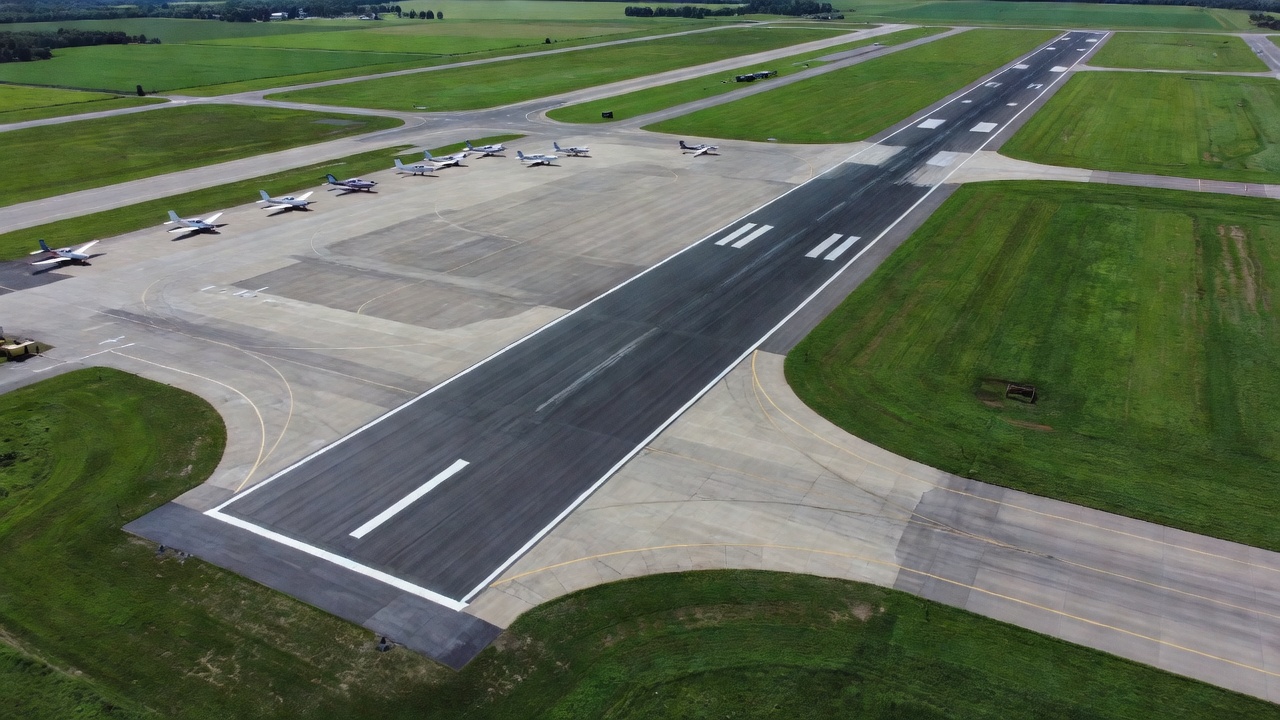
Microsurfacing for Airport Pavements
The application of microsurfacing to airport pavements has grown steadily since the early 2000s as airport operators seek cost-effective, low-disruption pavement preservation strategies. The Federal Aviation Administration (FAA), under Advisory Circular 150/5320-6G (Airport Pavement Design and Evaluation), recognizes microsurfacing as an accepted pavement preservation technique for flexible (asphalt) airfield pavements. While the FAA’s primary guidance addresses structural pavement design using FAARFIELD software, Chapter 4 of AC 150/5320-6G explicitly includes pavement preservation treatments, including microsurfacing, as a strategy for extending the service life of structurally sound pavements without increasing structural capacity.
The International Civil Aviation Organization (ICAO), through Annex 14, Aerodromes and ICAO Doc 9157, Aerodrome Design Manual, Part 3 (Pavements), establishes the performance requirements for airfield pavements including friction characteristics, surface evenness, and load-bearing capacity. While ICAO does not prescribe specific preservation treatment types, the organization requires that paved surfaces maintain adequate friction characteristics (expressed as friction number or µ) and that surface irregularities, including ruts and depressions, do not exceed operational tolerances. Microsurfacing directly addresses both requirements by restoring skid resistance through the rough aggregate texture and by correcting shallow ruts and surface irregularities.
Suitable Airport Applications. Microsurfacing is most effectively applied on airport pavements that meet the following criteria:
- General aviation and reliever airports with asphalt pavement surfaces and traffic levels that do not justify the cost of structural overlays
- Secondary runways (non-primary) where aircraft operations consist of smaller business jets, turboprops, and piston-engine aircraft
- Taxiways and taxi lanes where rutting from turning movements and slow-speed traffic is a recurring issue
- Aprons and parking areas where surface sealing and friction restoration are the primary needs, and where the chemical resistance of the polymer-modified binder provides protection against fuel and hydraulic fluid spills
- Service roads and perimeter roads within the airfield boundary
The use of microsurfacing on primary commercial runways is less common, as the structural demands of heavy transport-category aircraft (Boeing 737, Airbus A320, and larger) operating at high tire pressures may exceed the structural capability of thin surface treatments. However, for primary runways at general aviation airports and for non-precision approach runways at regional airports, microsurfacing has been successfully applied by agencies including the Kentucky Transportation Cabinet (Capital City Airport), Ohio Department of Transportation, and numerous municipal airport authorities.
Airport-Specific Considerations. Before applying microsurfacing to airport pavements, several airfield-specific requirements must be addressed:
- Friction testing: Pre- and post-treatment friction testing must be performed using continuous friction measuring equipment (CFME) per ICAO or FAA protocols to verify that the microsurfacing achieves the target friction values.
- Surface preparation: Existing pavement must be clean and free of oil, fuel, rubber deposits, vegetation, and loose material. Crack sealing must be completed before microsurfacing application to prevent reflective cracking.
- Pavement marking compatibility: Microsurfacing covers existing pavement markings and markings must be restored after application. Temporary markings may be needed during the cure period.
- Ironworks clearance: The applied thickness (typically 10-15 mm) must not create a step or lip at the edge of pavement lighting fixtures (in-pavement lights), drainage grates, or other embedded hardware. These fixtures may require height adjustment or removal and reinstallation.
- Aircraft tire compatibility: The microsurfacing aggregate must be non-polishing and compatible with aircraft tire rubber compounds. Aggregate polish value (PSV) testing should confirm adequate long-term friction retention.
Condition and Performance Inspection
A systematic inspection program is essential to verify that the microsurfacing application meets quality standards and to monitor its performance over the service life. Inspection activities are divided into three phases: pre-application inspection (verifying the existing pavement is suitable), during-application inspection (quality control during placement), and post-application inspection (acceptance and performance monitoring).
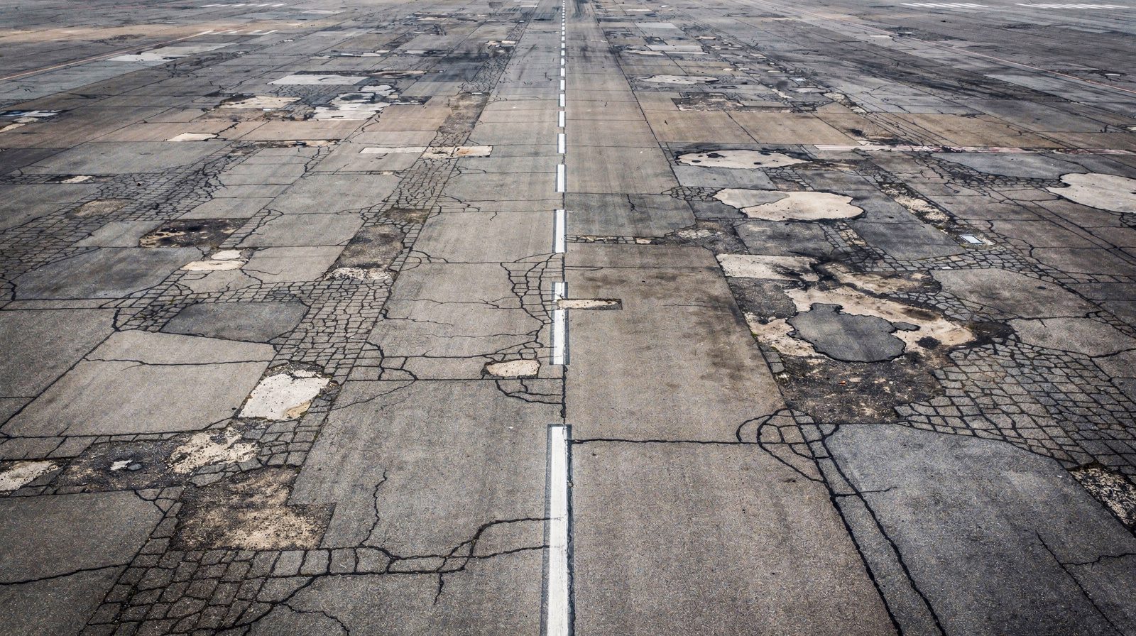
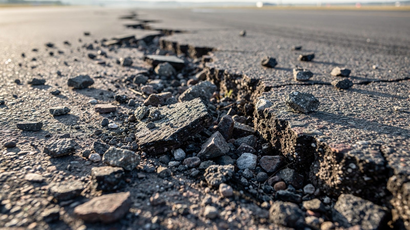
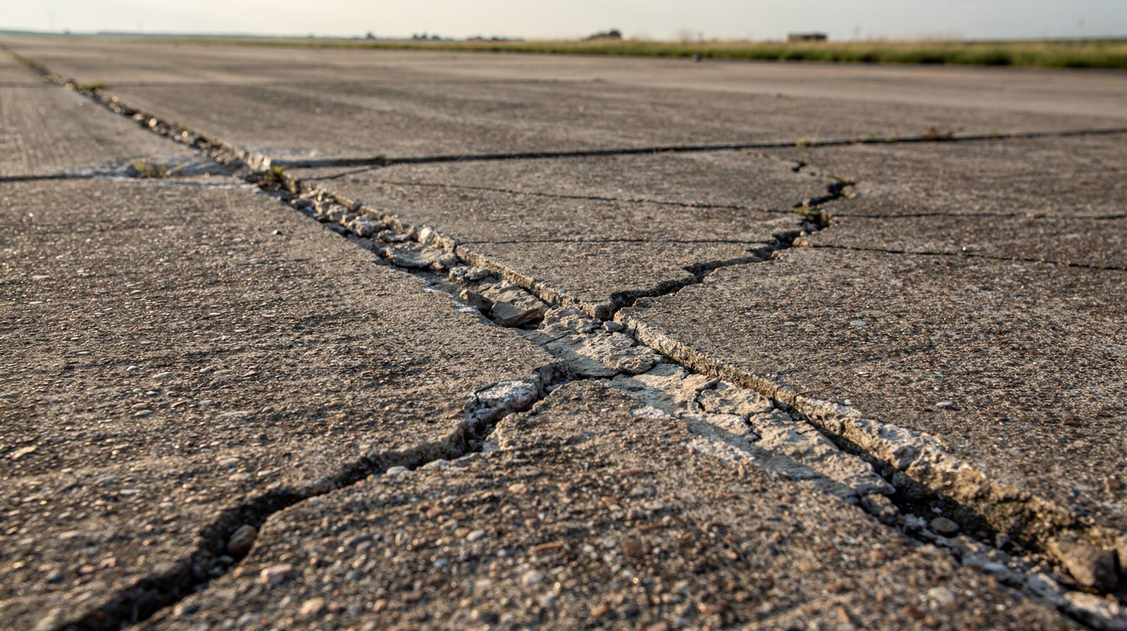
Pre-Application Inspection. The existing pavement must be evaluated for structural adequacy, surface condition, and surface cleanliness. The pavement must be structurally sound, free of alligator cracking, base failures, or extensive full-depth cracking. Surface distresses such as raveling, oxidation, flushing, and narrow cracking (less than 3 mm width) are acceptable candidates for treatment. Cracks wider than 3 mm must be sealed before microsurfacing application. The surface should be swept clean of loose debris, vegetation, and contaminants. If rubber deposits are present on runways, rubber removal (chemical or mechanical) must precede application. Areas of fuel or oil contamination must be cleaned or removed to ensure bonding of the microsurfacing to the underlying pavement.
During-Application Inspection. Key quality control checks during placement include:
- Mix consistency: The mixture must be uniform in color and consistency, free of lumps, balls of uncoated aggregate, or areas of excess emulsion (stripping).
- Spreader box operation: The augers must be turning freely and the strike-off must be set at the correct height to achieve the target thickness.
- Coverage and texture: The spread rate must be uniform with no bare spots or areas of excess accumulation. The burlap drag must produce a consistent final texture without longitudinal streaks or washboarding.
- Longitudinal joints: Adjacent passes must overlap by 50-100 mm and be feathered to create a seamless surface.
- Transverse joints: If unavoidable (with non-continuous equipment), joints must be feathered or overlapped to prevent bump formation.
- Ambient conditions: Application must stop if ambient temperature drops below 10°C, if rain is expected within the curing window, if the pavement surface temperature is below 10°C or above 45°C, or if wind conditions prevent uniform application.
- Cohesion monitoring: A field cohesion test (ISSA TB 139) should be performed at the start of production and periodically throughout the day to verify that the mixture is achieving the target rate of strength gain.
Post-Application Inspection. After placement and curing, the finished surface is inspected for:
- Surface evenness: Measured using a 3-meter straightedge. Deviations should not exceed ±6 mm for runways and ±10 mm for taxiways and aprons.
- Texture depth: Measured using the sand patch method (ASTM E965). Minimum texture depth should be 0.5 mm for new microsurfacing.
- Friction values: Measured using CFME or a portable friction tester. Target friction numbers vary by aircraft category and runway type per ICAO and FAA guidance.
- Edge condition: The feathered edges should be uniform and well-bonded. No delamination, curling, or edge ravelling should be present.
- Bond testing: If delamination is suspected, a pull-off adhesion test or core sample extraction is used to verify bond strength between the microsurfacing and the underlying pavement.
Performance Monitoring Over Service Life. During the service life of the microsurfacing (typically 4 to 7 years), periodic inspections should document the development of any of the following distresses: surface ravelling (loss of aggregate), flushing (excess binder rising to the surface under heat and traffic), cracking (reflective cracks propagating through the microsurfacing layer), tracking (pickup of material by aircraft or vehicle tires during hot weather), delamination (loss of bond between microsurfacing and underlying pavement), and wear (loss of texture depth and friction). Each distress type has a defined severity level per the ISSA Performance Evaluation Guidelines, and the inspection records inform the decision on when retreatment is needed.
Service Life and Retreatment Intervals
Microsurfacing provides a service life of 4 to 7 years on structurally sound pavements with properly designed and constructed applications, based on data from FHWA studies (FHWA-SA-94-051), ISSA performance databases, and agency experience documented in research papers such as the Canadian Technical Asphalt Association review by Kucharek et al. (2010). On low-traffic roads with minimal distress and favorable environmental conditions, service life can extend beyond 10 years. The service life is influenced by the following factors:
| Factor | Impact on Service Life |
|---|---|
| Pre-existing pavement condition | Good condition (Pavement Condition Index >70) enables longer life, deteriorated base shortens life significantly |
| Traffic volume and loading | High traffic volume or heavy loads accelerate wear, microsurfacing is not a structural overlay |
| Aggregate quality and gradation | Type III (coarser) with higher abrasion resistance extends service life in high-stress applications |
| Emulsion polymer content | Higher polymer content (5%+ ) improves elasticity and resistance to reflective cracking |
| Climate and environment | Freeze-thaw cycles, UV exposure, and deicing chemicals accelerate aging |
| Construction quality | Proper calibration, uniform application, and good bonding are essential for longevity |
| Surface preparation | Inadequate crack sealing or cleaning reduces bond and leads to premature failure |
Cyclical Treatment Programs. Many transportation agencies implement microsurfacing as part of a cyclical preservation program with retreatment intervals of 5 to 7 years. Under this approach, a pavement receives its first microsurfacing treatment when it is in good structural condition (Pavement Condition Index 70 to 100), and subsequent treatments are applied at regular intervals to maintain the sealed surface and restore friction before significant distress develops. This strategy maximizes the cost-effectiveness of microsurfacing by preventing oxidation, water infiltration, and raveling of the underlying pavement. The Kentucky Transportation Cabinet, for example, treats selected pavements on a 5-to-7-year cycle, reporting that early-cycle microsurfacing delays the need for structural hot-mix overlays by 10 to 15 years.
For airport pavements, the retreatment decision is driven by friction deterioration (measured by CFME), surface ravelling (loss of aggregate matrix), or the reappearance of rutting and surface irregularities. The FAA’s AC 150/5320-6G recommends that friction surveys be conducted at intervals of 1 to 3 years on runways with more than 300 annual departures. When friction values fall below the maintenance planning level (established by each airport or jurisdiction), retreatment with microsurfacing or an alternative surface restoration method is triggered.
Life Cycle Cost Comparison. Microsurfacing is one of the most cost-effective pavement preservation treatments on a cost-per-year-of-life-extended basis. The typical unit cost ranges from $3.00 to $6.00 per square meter ($2.50 to $5.00 per square yard) depending on geographic region, aggregate availability, project size, and layer thickness. This compares favorably to thin hot-mix asphalt overlays ($12 to $25 per square meter) and structural overlays ($30 to $60 per square meter). The equivalent annualized cost of microsurfacing (dividing the unit cost by the expected service life) typically ranges from $0.50 to $1.50 per square meter per year, making it among the lowest-cost preservation options for high-traffic pavements. Additionally, studies by Nouryon (formerly AkzoNobel) show that microsurfacing is more eco-efficient than thin hot-mix overlays, consuming less non-renewable energy and emitting less CO₂ per square meter of treated surface, due to the elimination of aggregate drying and heating during production.
Distress Identification and Troubleshooting
Recognizing and addressing the common distresses that affect microsurfacing is essential for maximizing the service life of the treatment and preventing premature failure. The following is a summary of the most frequently encountered distress mechanisms:
Ravelling (Loss of Aggregate). Aggregate particles become dislodged from the surface, leaving a rough, pitted texture. This is typically caused by insufficient binder content, poor aggregate-emulsion compatibility, premature traffic loading before adequate cohesion develops, or aging and oxidation of the binder. Prevention involves verifying the mix design wet track abrasion loss (ISSA TB 100), ensuring proper curing time before opening to traffic, and using polymer-modified binders with higher durability.
Flushing (Excess Binder). Binder rises to the surface, creating a shiny, sticky film that reduces friction and can cause tracking onto aircraft tires or vehicle wheels. Causes include excessive emulsion content, inadequate aggregate voids, placement in hot conditions without adjusting mix design, or insufficient filler content. Correction may require sand blotting or, in severe cases, removal and replacement.
Delamination (Loss of Bond). The microsurfacing layer separates from the underlying pavement, often visible as rattling loose pieces or cracked, detached areas. This occurs when the existing surface is contaminated (dust, oil, moisture), when a bond coat is improperly applied or omitted, when the microsurfacing is placed on a damp or frozen surface, or when reflective cracks propagate from an unstable substrate. Prevention requires thorough surface preparation, tack coat if specified, and strict moisture control during placement.
Reflective Cracking. Cracks in the underlying pavement propagate through the microsurfacing layer within 6 to 18 months. While microsurfacing seals the surface and waterproofs the pavement, it does not prevent crack reflection if the underlying pavement has active crack movement. Crack sealing before microsurfacing is essential for mitigating this distress.
Premature Trapping and Tire Tracking. In hot weather, the microsurfacing may be too soft and pick up under aircraft or vehicle tires, or trap rubber particles from tires. This is generally a function of binder grade selection and polymer content. Using higher-softening-point binders (minimum 57°C ring-and-ball softening point per ISSA A143) and adequate polymer modification minimizes this risk.
By understanding these distress mechanisms and addressing them through proper mix design, surface preparation, application procedures, and inspection protocols, airport operators and pavement engineers can achieve the full service life potential of microsurfacing as a pavement preservation tool. When applied as part of a comprehensive pavement management system with regular condition surveys and timely retreatment, microsurfacing is one of the most effective and sustainable strategies for maintaining the safety, friction, and serviceability of high-traffic pavements, including the demanding environment of airport airfields.
Frequently Asked Questions
- What is microsurfacing and how does it differ from slurry seal?
- Microsurfacing is a polymer-modified, cold-mix surface treatment that uses a chemical break mechanism rather than water evaporation for curing. It contains at least 3% polymer solids by weight of bitumen, uses 100% crushed aggregate with a coarser gradation (Type II or Type III), and can be applied in variable thicknesses up to 38 mm for rut filling. Slurry seal relies on evaporation, uses lower-quality aggregates, typically contains no polymer, and is limited to thinner single-layer applications on low-traffic surfaces.
- How is microsurfacing applied to pavement surfaces?
- Microsurfacing is applied using a specialized mix-paver, either a self-contained slurry truck for smaller projects or a continuous paving machine with feed conveyors for large-scale work. The machine proportionally meters aggregate, polymer-modified emulsion, water, and additives into an on-board pugmill mixer. The mixed material discharges into a spreader box (micro box) with augers that distribute it evenly across the pavement width. A following burlap drag finishes the surface texture. Application rates range from 3 to 14 kg/m² per single pass.
- What mix design standards govern microsurfacing?
- Microsurfacing mix design follows ISSA A143 (Recommended Performance Guidelines for Micro Surfacing), ASTM D6372, and AASHTO MP 31. These standards specify aggregate gradation bands (Type II and Type III), emulsion residue properties (minimum 62% residue, softening point minimum 57°C, penetration 40-90 dmm), cohesion testing (minimum 12 in-lbs at 30 minutes, 23 in-lbs at 60 minutes), wet track abrasion loss (maximum 807 g/m²), and excess asphalt determination by loaded wheel sand adhesion testing.
- Why is microsurfacing suitable for airport pavements?
- Microsurfacing is suitable for airport pavements, including runways, taxiways, and service roads, because it restores skid resistance (friction number), fills shallow ruts without requiring structural mill-and-fill, seals the surface against fuel and water infiltration, cures rapidly for minimal airfield downtime, and is applied in thin layers (10-15 mm) that do not alter pavement elevation or clearances. FAA and ICAO guidance recognizes surface treatments like microsurfacing as a valid pavement preservation option for general aviation and secondary airfield pavements.
- What is the expected service life of microsurfacing?
- Microsurfacing provides 4 to 7 years of service life on structurally sound pavements with properly selected and applied materials. On low-traffic roads with minimal distress, service life can extend to 10 years. Periodic reapplication every 5 to 7 years (cyclical treatment programs) is recommended to maintain seal integrity and friction. Environmental factors, pre-existing pavement condition, traffic levels, and construction quality are the primary determinants of actual longevity.