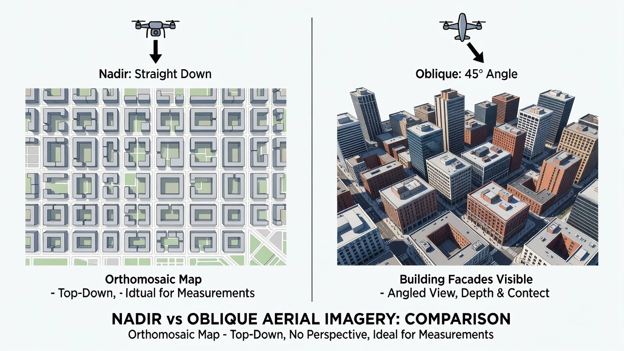
Nadir imagery is captured with the camera pointing straight down, perpendicular to the ground, producing minimal perspective distortion for accurate orthomosaic generation, mapping, and measurement. It is the standard orientation for drone photogrammetry and aerial surveying.
Nadir imagery is a type of aerial photograph captured with the camera axis oriented at 90 degrees to the ground surface — pointing directly downward. The term nadir originates from astronomy, where it describes the point on the celestial sphere directly beneath an observer, opposite the zenith. In aerial photography, satellite remote sensing, and drone-based photogrammetry, the nadir point is the location on the ground that lies vertically beneath the perspective center of the camera lens.
In the context of aerial surveying, the nadir orientation produces images with the least amount of perspective distortion and the most uniform scale across the entire frame. This geometric purity is what makes nadir imagery the default, standard orientation for orthomosaic generation, planimetric mapping, and quantitative measurements in virtually all drone photogrammetry workflows. Unlike oblique imagery, where pixels near the bottom of the frame are closer to the camera than those at the top, nadir images maintain a consistent ground sample distance (GSD) — the real-world distance represented by each pixel — across the entire photograph.
Technical Definition and Coordinate System
The Esri GIS Dictionary defines nadir as “the point on the ground vertically beneath the perspective center of the camera lens or scanner’s detectors, or the point of convergence (vanishing point) for all vertical rays within a scene.” This definition carries two critical implications for aerial surveyors.
First, the nadir point is the only location in an aerial photograph that is completely free from relief displacement — the apparent shift in object position caused by terrain elevation changes. As you move away from the nadir point toward the edges of the frame, relief displacement increases proportionally. This is why nadir-oriented images are preferred for mapping flat terrain: they minimize the geometric corrections needed during orthorectification.
Second, the nadir defines the vertical axis of the camera coordinate system. In photogrammetry, the interior orientation of the camera — focal length, principal point, lens distortion parameters — is calibrated relative to the nadir direction. Any deviation from true nadir (known as tip or tilt) introduces systematic errors that must be modeled and removed during photogrammetric processing. Modern drone gimbals can maintain nadir orientation within ±0.1° under stable conditions, but wind gusts and aggressive maneuvering can introduce tilt that degrades final accuracy.
The relationship between nadir and GSD follows a simple inverse-square law: GSD = (flight altitude × sensor pixel pitch) / focal length. For a given camera, doubling the flight altitude doubles the GSD, meaning each pixel covers twice the ground distance in both dimensions, quadrupling the area per pixel. Nadir imagery produces the most predictable GSD because the optical path length is the same across the entire sensor — the camera-to-ground distance is constant for all pixels, unlike oblique imagery where path length varies significantly across the frame.
The Geometry of Nadir Capture
When a camera is oriented in true nadir position, the optical axis of the lens is perpendicular to the ground plane. This means the image plane and the ground plane are parallel to each other. In this configuration, the geometry of the captured image follows a simple central projection model where the scale is uniform across the entire image, assuming flat terrain.
The mathematical model for nadir image geometry is significantly simpler than for oblique images. In a true nadir image, the transformation from 3D world coordinates to 2D image coordinates can be approximated with a simple scaling and translation, requiring only four parameters. Oblique images, by contrast, require full projective transformation with eight or more parameters, plus additional modeling for variable GSD, perspective foreshortening, and occluded areas.
This geometric simplicity has practical consequences. Nadir images process faster in photogrammetry pipelines because feature matching algorithms have an easier time finding corresponding points when scale variations between images are minimal. The computational cost of Structure from Motion (SfM) processing for nadir-only datasets can be 30-50% lower than for datasets with significant oblique content, simply because the geometric constraints are tighter and the solution converges faster.
Advantages of Nadir Imagery
Nadir imagery offers several distinct advantages that make it indispensable for aerial surveying and mapping.
Minimal Perspective Distortion. In a true nadir image, all ground features appear in their correct geometric relationship, without the foreshortening or keystone effects common in oblique photography. A rectangular building roof appears rectangular in nadir view, not trapezoidal as it would in an oblique view. This makes nadir imagery ideal for measuring distances, areas, and angles directly on the image.
Uniform Ground Sample Distance. Every pixel in a nadir image represents the same physical ground area, assuming flat terrain. This uniform resolution means that a crack measurement taken near the image center has the same accuracy as one taken near the image edge. In oblique imagery, resolution can vary by a factor of 3x or more between the near and far edges of a single photograph.
Optimal for Orthomosaic Generation. Orthomosaics — geometrically corrected, seamless composite images — rely on nadir imagery as their primary input. The orthorectification process removes terrain-induced displacements and camera tilt effects to produce a map-accurate image where every pixel is positioned in its true geographic location. Nadir images require minimal orthorectification because they already approximate the orthographic projection that orthomosaics aim to achieve.
Predictable Overlap Patterns. When flying a nadir grid mission, the overlap between adjacent images follows a clean, predictable pattern determined solely by the flight altitude, speed, and camera trigger interval. This predictability simplifies flight planning and ensures complete coverage with minimal redundancy. Mission planning software can calculate exact camera trigger positions to achieve target overlap percentages with mathematical precision.
Superior for Planimetric Mapping. Planimetric maps — maps showing only horizontal positions of features without elevation — are best produced from nadir imagery because the horizontal geometry is already well-preserved. Features like pavement markings, property boundaries, utility covers, and building footprints can be digitized directly from nadir orthomosaics with high positional accuracy.
Higher Coverage Efficiency. A nadir mapping mission covers more ground per flight than an oblique mission at the same altitude because the camera’s field of view projects as a rectangle on the ground rather than a trapezoid. For a typical drone flying at 120 m (400 ft) AGL with a 24 mm equivalent lens, a nadir image covers approximately 200 × 150 m of ground, while an oblique image at 45° covers a larger total area but with highly variable resolution and significant occlusion behind tall objects.
Nadir Imagery in Drone Photogrammetry
Nadir imagery is the foundation of drone-based photogrammetry. The standard workflow for generating orthomosaics, digital surface models (DSMs), and 3D point clouds begins with the acquisition of nadir images flown in a systematic grid pattern.
The flight planning parameters for nadir photogrammetry are well-established. The American Society for Photogrammetry and Remote Sensing (ASPRS) recommends a minimum of 60% forward overlap and 30% side overlap for basic orthomosaic generation, though most practitioners use 75-80% forward overlap and 60-70% side overlap for high-accuracy work. The additional overlap ensures that every ground point appears in at least three to five images, providing the redundancy needed for reliable automated tie point matching and bundle adjustment.
Ground Sample Distance and Altitude. The relationship between flight altitude and GSD is linear: GSD = (altitude × pixel pitch) / focal length. For a DJI Mavic 3 Enterprise with a 4/3-inch CMOS sensor (3.3 μm pixel pitch) and a 24 mm equivalent focal length flying at 100 m AGL, the GSD is approximately 1.3 cm/pixel. At this resolution, pavement cracks as narrow as 4 mm can theoretically be detected, though practical detection limits are typically 2-3 times the GSD.
Terrain Following. For sites with significant elevation changes, terrain-following flight modes maintain a constant AGL distance, keeping GSD consistent across the survey area. Without terrain following, nadir imagery captured over hilly terrain will have variable resolution — higher resolution over hilltops where the drone is closer, lower resolution in valleys where it is farther away. Most professional mapping drones and flight software now support terrain-following using onboard LiDAR, real-time terrain models, or pre-loaded digital elevation models.
Multi-Grid Patterns. For large-area surveys, nadir missions are typically flown in a double-grid (crosshatch) pattern: one pass with north-south flight lines, then a second pass with east-west flight lines. This crosshatch pattern improves 3D reconstruction quality by providing orthogonal viewing angles for every ground point, even though the camera remains in nadir orientation. The crosshatch pattern is especially important for sites with subtle topographic features that might be poorly reconstructed from a single flight direction.
Georeferencing. Nadir images must be georeferenced to produce usable mapping products. Direct georeferencing uses the drone’s onboard GPS/IMU to tag each image with approximate position and orientation. For survey-grade accuracy, ground control points (GCPs) are placed at surveyed locations across the site and visible in the imagery. RTK and PPK corrections further improve direct georeferencing accuracy. With RTK-enabled drones, absolute positional accuracy of 2-5 cm (horizontal) and 4-7 cm (vertical) can be achieved without GCPs. With well-distributed GCPs, accuracies of 1-2 cm are routinely attainable.
Nadir vs Oblique Imagery: A Detailed Comparison
Understanding the differences between nadir and oblique imagery is essential for selecting the right capture strategy for any given project.
Parameter
Nadir Imagery
Oblique Imagery
Camera angle
90° (straight down)
30°-60° off vertical
Perspective distortion
Minimal, uniform scale
Significant, variable scale
GSD consistency
Uniform across frame
Variable (3:1 or more)
Orthomosaic suitability
Excellent (primary input)
Poor (auxiliary only)
3D model completeness
Poor walls, roofs only
Complete with facades
Coverage efficiency
High (per flight)
Lower (more passes needed)
Processing time
Faster (simpler geometry)
Slower (more complex)
Measurement accuracy
Higher for horizontal
Higher for vertical surfaces
Best for
Maps, orthomosaics, area measurement
3D models, facade inspection
Nadir imagery excels at capturing horizontal surfaces — rooftops, pavement, terrain, agricultural fields. It produces clean, geometrically accurate maps that can be used directly for measurement and analysis. Oblique imagery, on the other hand, captures vertical surfaces that nadir imagery cannot see: building facades, bridge abutments, retaining walls, and cliff faces.
The choice between nadir and oblique is not binary. Most professional aerial survey projects use both. A typical mission profile includes a nadir grid pass for the orthomosaic and horizontal geometry, followed by four oblique passes (north, south, east, west) at 45° for facade detail. Some high-end capture systems use five-camera arrays that capture one nadir and four oblique images simultaneously, eliminating the need for multiple flight passes.
Nadir for Pavement and Runway Inspection
Nadir imagery is the preferred capture orientation for pavement inspection using drones. The straight-down perspective is ideally suited for documenting pavement surface condition because the inspection targets — cracks, rutting, raveling, potholes, surface defects — are all features visible on the horizontal pavement surface.
Pavement Condition Index (PCI) Evaluation. The standard methodology for pavement condition assessment, ASTM D5340, relies on visual inspection of surface distress types, severity levels, and extent. Nadir drone imagery provides a complete, permanent visual record of the pavement surface that can be systematically analyzed for PCI calculation. High-resolution orthomosaics generated from nadir imagery enable inspectors to identify and classify distresses across entire pavement networks without walking the site.
Crack Detection and Measurement. Sub-centimeter GSD nadir imagery (0.5-1.0 cm/pixel) enables automated crack detection using computer vision algorithms. Longitudinal cracks, transverse cracks, alligator cracking, and block cracking are all visible in high-resolution nadir imagery. Crack widths as narrow as 2-3 mm can be measured from orthomosaics with appropriate GSD and sharp image quality. Modern deep learning-based crack detection systems achieve 90-95% detection rates on nadir pavement imagery with false positive rates below 5%.
Runway FOD Detection. Foreign Object Debris (FOD) on airport runways poses a serious safety risk. Nadir drone imagery captured during routine runway inspections can detect FOD items as small as 2 cm in diameter when flown at appropriate altitudes. Several major airports worldwide now use drone-based nadir inspection as part of their FOD management programs, supplementing or replacing traditional vehicle-based FOD patrols.
ICAO Annex 14 Compliance. The International Civil Aviation Organization (ICAO) Annex 14 — Aerodromes specifies surface condition monitoring requirements for airports. While ICAO does not mandate specific inspection technologies, the annex requires that runway surface conditions be regularly assessed and reported. Nadir drone imagery provides measurable, verifiable data that satisfies these regulatory requirements while reducing runway closure times compared to traditional visual inspection methods. The FAA’s Advisory Circular 150/5200-18C also supports the use of advanced technologies, including drone-based inspection, for airport pavement management.
Limitations of Nadir Imagery
Despite its many advantages, nadir imagery has significant limitations that surveyors and inspectors must understand.
Invisibility of Vertical Surfaces. The most fundamental limitation of nadir imagery is that it cannot capture vertical surfaces. Building facades, bridge sides, tunnel walls, dam faces, and retaining walls are either completely invisible or appear only as narrow slivers in nadir images. For infrastructure inspection, this means that nadir-only inspection misses critical structural elements. Bridge girders, bearing assemblies, abutment walls, and pier columns are not visible from the nadir perspective.
The “Melting Building” Effect. When nadir imagery alone is used for 3D model generation, vertical structures exhibit what photogrammetrists call the “melting building” effect — walls that are distorted, poorly textured, or merged together at their bases. This occurs because the photogrammetry software has insufficient geometric information to reconstruct vertical surfaces from nadir-only data. The model captures the roof accurately but has no data points on the walls, forcing the algorithm to interpolate between roof edges and ground-level features.
Occlusion and Undercuts. Nadir imagery cannot see under overhangs, behind elevated structures, or into recessed areas. Deep roof overhangs, covered walkways, bridge undersides, and tunnel entrances are all invisible from the nadir perspective. For these areas, oblique or horizontal camera orientations are essential.
Reduced Accuracy on Steep Terrain. On steep slopes, nadir imagery’s uniform-GSD advantage diminishes. The effective GSD on a slope surface is the product of the nominal GSD and the secant of the slope angle. A 30° slope increases the effective GSD by 15%, while a 45° slope doubles it. Terrain-following flight helps but does not fully compensate for this effect.
Shadow Limitations. Nadir imagery captured at low sun angles suffers from long shadows cast by trees, buildings, and terrain features. These shadows obscure pavement surfaces and may hide defects or features of interest. Flying during midday hours (10:00 AM to 2:00 PM) minimizes shadow problems, and overcast conditions provide ideal diffuse lighting that eliminates shadows entirely.
Oblique Imagery for Vertical Surfaces
When the inspection target includes vertical surfaces — building facades, bridge sides, retaining walls — oblique imagery becomes necessary. Oblique aerial imagery is captured with the camera tilted at an angle, typically between 30° and 60° off the vertical axis. This perspective reveals the sides of structures that nadir imagery cannot see.
Building Facade Inspection. For building facade inspections under programs like New York City’s Facade Inspection Safety Program (FISP), oblique drone imagery provides a cost-effective alternative to traditional swing-stage inspections. Oblique imagery captures wall conditions, window sealants, masonry cracks, corrosion, and other facade defects with sufficient resolution for condition assessment. A typical facade inspection mission captures oblique imagery from four cardinal directions to ensure all four building sides are documented.
Bridge and Infrastructure Inspection. Bridge inspection requires coverage of all structural elements: deck surface, girders, bearings, abutments, piers, and approach slabs. Nadir imagery captures the deck surface, but the remaining elements require oblique or even horizontal camera angles. Drone-based bridge inspection protocols developed by the Federal Highway Administration (FHWA) and state DOTs specify multi-angle capture plans that include nadir deck surveys, oblique girder surveys, and horizontal bearing surveys.
The Oblique Orbit Pattern. For individual structure inspection, an orbital flight pattern with oblique camera angle is more efficient than grid-based nadir missions. The drone flies a circular path around the structure, maintaining a constant distance and altitude while the camera points inward at a fixed oblique angle. This orbit pattern ensures every vertical surface is captured from multiple lateral angles, providing complete coverage for 3D reconstruction.
Combined Nadir and Oblique Flight Plans
The most complete aerial survey datasets are produced by combining nadir and oblique captures in a single flight plan. The nadir component provides the accurate horizontal geometry and orthomosaic, while the oblique component adds the vertical detail needed for complete 3D reconstruction.
The Standard Five-Pass Mission. The industry-standard approach for comprehensive aerial survey of structures involves five distinct flight passes:
Nadir grid pass — Camera at 90°, flown in a lawnmower pattern with 75-80% overlap for orthomosaic base
North oblique pass — Camera tilted 45° to the north, flown parallel to the survey area
South oblique pass — Camera tilted 45° to the south, capturing opposite facades
East oblique pass — Camera tilted 45° to the east
West oblique pass — Camera tilted 45° to the west
This five-direction capture ensures every building surface is photographed from at least two different camera positions, providing the geometric constraints needed for complete 3D reconstruction. Each oblique pass typically uses lower overlap (60-70%) than the nadir pass since the primary goal is geometric diversity rather than pixel-level redundancy.
Processing Combined Datasets. Photogrammetry software processes nadir and oblique images together in a single bundle adjustment. The nadir images provide the stable horizontal reference frame, while the oblique images contribute the vertical constraints that resolve the full 3D geometry. Modern SfM pipelines like Pix4Dmapper, Agisoft Metashape, and DJI Terra handle mixed nadir-oblique datasets automatically, identifying and matching tie points across both image types.
Flight Time Considerations. Adding oblique passes approximately doubles the total flight time compared to a nadir-only mission. For a 50-acre (20-hectare) site, a nadir-only mission at 100 m altitude with 75% overlap takes approximately 25-30 minutes of flight time. Adding the four oblique passes increases total flight time to 55-70 minutes, requiring either multiple batteries or a drone with extended endurance. The trade-off between flight time and model completeness must be evaluated for each project.
Nadir Imagery Accuracy Standards
Positional accuracy of nadir-derived mapping products is governed by established standards from ASPRS, the Federal Geographic Data Committee (FGDC), and the National Map Accuracy Standards (NMAS).
ASPRS Positional Accuracy Standards. The ASPRS Positional Accuracy Standards for Digital Geospatial Data (2015) classify orthoimagery and other digital geospatial data into accuracy classes based on Root Mean Square Error (RMSE) evaluated against independent check points. For orthoimagery derived from nadir imagery, the standard specifies that RMSE shall be computed in both horizontal dimensions (X and Y) and reported at the 95% confidence level (RMSE × 1.7308 for normally distributed errors).
ASPRS Class
RMSE (cm)
GSD (cm)
Typical Flight Altitude (m)
Class I
2.5
1.0
80
Class II
5.0
2.0
160
Class III
10.0
4.0
320
Class IV
20.0
8.0
640
Factors Affecting Accuracy. The ultimate accuracy of nadir-derived mapping products depends on several interlinked factors:
Camera calibration — Accurately known focal length, principal point, and lens distortion parameters are essential for unbiased photogrammetric reconstruction. Uncalibrated or poorly calibrated cameras introduce systematic errors that cannot be removed during processing.
Image quality — Sharp focus, correct exposure, low noise, and minimal motion blur all contribute to accurate feature matching and precise triangulation. Blurry or noisy images reduce the precision of tie point measurements and degrade final accuracy.
Overlap quality — Consistent, well-distributed overlap ensures all ground points are imaged from multiple perspectives. Gaps or inconsistent overlap leave areas with weak geometric constraints and reduced accuracy.
GCP distribution — Ground control points should be evenly distributed across the survey area, including the perimeter, with higher density in areas of complex terrain. Poor GCP distribution allows the photogrammetric solution to drift, particularly at the survey boundaries.
GNSS positioning — The accuracy of the camera position tag directly affects the initial alignment and final absolute accuracy. RTK-corrected positions (1-3 cm accuracy) produce significantly better results than standalone GPS (2-5 m accuracy).
Terrain complexity — Steep slopes, tall structures, and dense vegetation all reduce the effective accuracy of nadir-derived models by introducing areas where the geometric reconstruction is less constrained.
Validation and Quality Reporting. Professional nadir mapping projects include validation against independently surveyed check points. The RMSE at these check points is computed and reported as part of the project quality documentation. The spatial distribution of residuals is analyzed for systematic trends that might indicate uncorrected camera calibration errors, datum mismatches, or processing artifacts.
Best Practices for Nadir Imagery Capture
Achieving optimal results from nadir imagery requires careful attention to every phase of the capture and processing workflow.
Pre-Flight Planning. Before any nadir capture mission, the survey area should be assessed for terrain complexity, obstacle hazards, and access restrictions. Flight altitude is selected based on the required GSD — the lower the altitude, the higher the resolution, but the longer the flight time. A practical rule of thumb is to select an altitude where the desired GSD is achievable within a single battery cycle for the survey area. For large areas, missions must be segmented into multiple flights.
Camera Settings. Use manual exposure mode to prevent the camera from adjusting exposure between images, which would cause brightness variations in the final orthomosaic. Set shutter speed to at least 1/1000 second to eliminate motion blur from drone vibration and forward motion. Use the lowest ISO (100-400) that achieves correct exposure, minimizing noise that degrades feature matching. Aperture should be set to f/4 to f/8 — wide enough to avoid diffraction blur but narrow enough for adequate depth of field. Set focus to manual at infinity to prevent the autofocus from hunting between frames.
Overlap Optimization. The minimum overlap for reliable orthomosaic generation is 60% forward and 30% side, but 80% forward and 70% side is recommended for high-accuracy work. The additional overlap provides redundancy for quality control and ensures complete coverage even with minor GPS drift or wind-induced flight path deviations. For sites with tall structures, overlap should be increased further to ensure the structure tops are captured in multiple images.
Lighting Conditions. Fly during midday hours (10 AM to 2 PM) when the sun is highest to minimize shadows. Overcast conditions with stratus clouds provide ideal diffuse lighting that eliminates shadows entirely while maintaining adequate illumination. Avoid flying in direct sunlight with long shadows (early morning, late afternoon) as shadowed areas may be underexposed and lose detail. Avoid rain, fog, and high humidity that degrade image contrast.
Terrain Awareness. For sites with significant elevation changes, use terrain-following flight mode if available. This maintains constant altitude above ground level, keeping GSD consistent across the survey. Without terrain following, resolution will vary by the ratio of highest to lowest terrain elevation within the survey area.
GCP Placement. Distribute ground control points evenly across the survey area, including near the perimeter. Use targets that are 5-10 times the GSD in size for reliable identification in the imagery. Place GCPs on flat, stable surfaces away from tall obstacles that might cast shadows. Survey GCP positions with RTK GNSS equipment for centimeter-level accuracy.
Quality Assurance. After capture, inspect images for focus, exposure, and motion blur before leaving the site. Check for any gaps in coverage by reviewing the image footprints in the mission planning software. Capture at least 10% extra images at the survey boundaries to ensure edge-to-edge coverage after geometric corrections.
Metadata Integrity. Verify that image EXIF data contains accurate GPS coordinates, altitude, camera model, and lens parameters. Corrupted or missing metadata can prevent proper georeferencing and may require manual correction during processing. RTK-corrected position tags should be verified against known survey marks where available.
Applications of Nadir Imagery Across Industries
Nadir imagery finds application across a wide range of industries and use cases.
Agriculture. Nadir multispectral imagery is the standard data source for precision agriculture, used to generate normalized difference vegetation index (NDVI) maps, identify crop stress, estimate yields, and guide variable-rate fertilizer application. The uniform resolution of nadir imagery ensures consistent plant health measurements across entire fields.
Construction and Earthworks. Construction site monitoring relies on nadir drone imagery to produce daily or weekly orthomosaics showing site progress, stockpile volumes, and grading accuracy. Cut-and-fill volume calculations from nadir-derived digital elevation models achieve accuracies of 1-3% when properly georeferenced.
Environmental Monitoring. Wetland delineation, coastal erosion monitoring, vegetation mapping, and environmental impact assessments all use nadir imagery as a primary data source. Platforms like GeoNadir provide specialized tools for environmental condition assessment using drone and satellite nadir imagery.
Insurance and Property Assessment. Insurance carriers use nadir orthomosaics to measure roof areas, assess property conditions, and document pre-existing damage for claims management. The ability to measure directly from georeferenced orthoimagery eliminates the need for physical site visits for many property assessment tasks.
Emergency Response. First responders use rapid-deployment nadir drone missions to map disaster scenes, search areas, and incident perimeters. The real-time orthomosaic capability enables incident commanders to see the full extent of a scene from a single top-down view, supporting tactical decision-making.
Urban Planning. Municipal planning departments use nadir orthoimagery as base maps for zoning analysis, property assessment, infrastructure planning, and urban development monitoring. Time-series nadir imagery enables change detection for identifying unauthorized construction, tracking development patterns, and monitoring compliance with planning regulations.
Summary
Nadir imagery — captured with the camera pointing straight down, perpendicular to the ground — is the fundamental data type for aerial surveying, mapping, and photogrammetry. Its uniform geometry, minimal perspective distortion, and consistent ground sample distance make it the optimal choice for orthomosaic generation, planimetric mapping, area measurement, and pavement inspection. The limitations of nadir imagery — particularly its inability to capture vertical surfaces — are well understood and can be overcome by supplementing with oblique imagery in combined capture plans. Professional aerial survey projects routinely integrate nadir and oblique data to produce complete, accurate, and usable geospatial products across surveying, construction, infrastructure inspection, agriculture, environmental monitoring, and emergency response applications.
Frequently Asked Questions
Nadir imagery refers to photographs taken with the camera pointing straight down, perpendicular to the ground surface. The term 'nadir' comes from astronomy, where it describes the point on the celestial sphere directly beneath an observer — the opposite of zenith. In aerial photography and remote sensing, nadir is the point on the ground vertically beneath the perspective center of the camera lens. Nadir images have minimal perspective distortion and uniform ground sample distance across the frame, making them the preferred orientation for orthomosaic generation, planimetric mapping, and GIS applications.
Nadir imagery points the camera straight down at 90° to the ground, capturing top-down views ideal for orthomosaics and area measurements. Oblique imagery tilts the camera between 30° and 60° off vertical to capture building facades, wall textures, and vertical surfaces. Nadir images have consistent ground sample distance and minimal perspective distortion, while oblique images have variable resolution but provide the side geometry needed for complete 3D reconstruction. Most professional surveys combine both for maximum accuracy.
Nadir imagery produces the best orthomosaics because the camera axis is perpendicular to the ground, eliminating perspective distortion that would otherwise cause scale variations across the image. Every pixel in a nadir image represents a consistent ground sample distance, and the overlap between adjacent images follows a predictable grid pattern. This uniformity allows photogrammetry software to stitch images with high accuracy and minimal geometric correction. The result is a seamless, georeferenced map where distances, areas, and angles can be measured directly.
For nadir drone photogrammetry, a minimum overlap of 70-80% forward overlap (along flight path) and 60-80% side overlap (between flight lines) is recommended for accurate orthomosaic and 3D model generation. For complex terrain or areas with tall structures, increasing overlap to 80-85% is advisable. Higher overlap ensures that every ground point appears in multiple images from different angles, which is essential for reliable feature matching, triangulation, and surface reconstruction in photogrammetry software.
Nadir imagery alone produces incomplete 3D models of buildings because it only captures roof surfaces, not vertical walls or facades. 3D models generated from nadir-only data exhibit the 'melting building' effect where walls are distorted or missing entirely. For complete building reconstruction, oblique imagery must be added to capture facade geometry and texture. A combined nadir + oblique flight plan is the standard approach for professional 3D modeling of structures.
The primary limitation of nadir imagery is its inability to capture vertical surfaces. Building facades, bridge sides, cliff faces, and other vertical structures are invisible or severely distorted in nadir-only datasets. Additionally, nadir imagery struggles with deep overhangs, undercuts, and recessed features. For infrastructure inspection of bridges, dams, and high-rise buildings, nadir imagery must be supplemented with oblique or even horizontal camera orientations to capture all surfaces requiring assessment.
Nadir photogrammetry accuracy depends on ground sample distance (GSD), flight altitude, image overlap, camera quality, and ground control. Consumer-grade drone workflows at 400 ft altitude with 75% overlap achieve 2-6 inch absolute positional accuracy. With ground control points (GCPs), high-resolution sensors, and RTK/PPK positioning, accuracies of 0.1-0.25 inch are achievable. The ASPRS Positional Accuracy Standards for Digital Geospatial Data provide the framework for evaluating and classifying nadir-derived orthoimagery accuracy.
Major flight planning platforms that support automated nadir capture include Pix4Dcapture, DroneDeploy, DJI Pilot, UgCS, Mission Planner, and Litchi. These tools generate systematic lawn-mower grid patterns with configurable overlap, altitude, and area coverage parameters. For professional surveying, dedicated mission planning software supports terrain-following flight, multi-grid patterns, and combined nadir-oblique mission profiles.
Yes, nadir imagery is the standard camera orientation for pavement and runway inspection using drones. The straight-down perspective captures the entire pavement surface with uniform resolution, making it ideal for detecting cracks, rutting, raveling, potholes, surface defects, and foreign object debris (FOD). Runway condition assessment programs at major airports increasingly rely on nadir drone imagery to produce high-resolution orthomosaics for Pavement Condition Index (PCI) evaluation under ASTM D5340 and ICAO Annex 14 requirements.
For nadir aerial photography, use manual exposure mode to prevent brightness variations between images. Set shutter speed fast enough to eliminate motion blur (typically 1/1000s or faster depending on drone speed and altitude). Use ISO as low as possible (100-400) to minimize noise. Aperture should be f/4 to f/8 for optimal sharpness across the frame. Set focus to manual at infinity to prevent focus hunting. Use a mechanical shutter if available to reduce rolling shutter distortion. Capture in RAW format for maximum post-processing flexibility.
Need Professional Aerial Inspection?
TarmacView provides expert nadir and oblique aerial inspection services for pavement, infrastructure, and aviation assets. Contact us for a custom survey proposal.
Glossary of Topography, Surface Features, and Elevation Surveying
A comprehensive glossary for topography, surface features, and elevation surveying, covering major concepts, tools, and technical standards from ICAO, USGS, and...
A vertical angle in surveying is measured in the vertical plane between a horizontal reference and a line of sight to a target above or below. It's crucial for ...
The zenith is the point in the sky directly above an observer, crucial in navigation, astronomy, surveying, and aviation as the reference for vertical alignment...
5 min read
Astronomy
Navigation
+3
Cookie Consent We use cookies to enhance your browsing experience and analyze our traffic. See our privacy policy.