Neoprene (polychloroprene) is a synthetic rubber widely used in bridge elastomeric bearings, compression joint seals, and bearing pads due to its resistance to weathering, ozone, oils, and moderate temperatures. Neoprene aging — cracking, stiffening, permanent set — is a key inspection finding. Covers neoprene properties, bearing pad specifications, deterioration mechanisms, and inspection criteria.
What is Neoprene in Bridge Bearings and Joints?
Definition and Material Properties
Neoprene is the commercial name for polychloroprene (CR) , a family of synthetic rubbers produced by the emulsion polymerization of chloroprene (2-chloro-1,3-butadiene). Invented by DuPont scientists in 1930 as the first commercially successful synthetic elastomer, neoprene was developed in response to the need for an oil-resistant rubber alternative. The molecular structure of polychloroprene features a chlorine atom attached to each monomer unit, which provides the material with its distinctive chemical resistance properties. The polymer backbone contains predominantly trans-1,4-polychloroprene configurational units, with the chlorine atoms creating polarity that reduces the material’s reactivity with ozone and hydrocarbon oils.
The physical and mechanical properties of neoprene make it exceptionally suitable for bridge bearing applications. Neoprene compounds used in bridge bearings typically exhibit a Shore A durometer hardness between 50 and 70, as specified by AASHTO M251 and ASTM D4014. This hardness range provides an optimal balance between load-bearing capacity and the ability to accommodate movement through shear deformation. The tensile strength of neoprene bridge bearing compounds typically ranges from 17.2 MPa (2,500 psi) to 20.7 MPa (3,000 psi) when tested in accordance with ASTM D412. The minimum elongation at break is specified at 350 percent for neoprene compounds after heat aging, ensuring the material retains sufficient ductility throughout its service life.
The shear modulus (G) of neoprene is the critical design parameter for bearing pads. AASHTO LRFD Bridge Design Specifications, Section 14.7.5.2, define the shear modulus range for elastomeric bearings as 0.55 MPa (80 psi) to 1.38 MPa (200 psi) at 73°F (23°C). The most commonly specified value for bridge bearing design is 0.90 MPa (130 psi) at 73°F, which provides a balance between stiffness for vertical load capacity and flexibility for horizontal movements. The shear modulus is affected by temperature — neoprene stiffens at low temperatures and softens at elevated temperatures. The temperature correction factor for neoprene shear modulus is approximately 0.2 percent per degree Fahrenheit above or below the reference temperature of 73°F, meaning a bearing at 0°F (-18°C) may have a shear modulus 15 percent higher than its room-temperature value.
Neoprene exhibits outstanding resistance to ozone and weathering, which is the primary reason for its dominance in bridge bearing applications. Ozone (O₃) is present in the atmosphere at concentrations typically between 0.01 and 0.10 parts per million (ppm) in rural areas and up to 0.50 ppm in urban environments with photochemical smog. Ozone molecules are highly reactive and attack unsaturated carbon-carbon double bonds in elastomer polymer chains. The chlorine atoms in neoprene’s molecular structure reduce the electron density of the double bonds, making them less susceptible to ozone attack compared to natural rubber or styrene-butadiene rubber (SBR). Accelerated ozone resistance testing per ASTM D1149 requires neoprene samples to show no cracking after 168 hours of exposure to 50 ppm ozone at 20 percent strain, a test that natural rubber typically fails within hours.
The operating temperature range for neoprene in bridge applications extends from approximately -40°F (-40°C) to 200°F (93°C). The glass transition temperature (Tg) of polychloroprene is approximately -45°C (-49°F), below which the polymer transitions from a flexible elastomeric state to a rigid glassy state. The brittleness temperature per ASTM D2137 is typically between -35°C and -45°C depending on the specific compound formulation. At the upper end of the temperature range, neoprene begins to undergo thermal oxidation at sustained temperatures above 250°F (121°C), though this temperature is rarely approached in bridge bearing service. The service temperature range is therefore adequate for all but the most extreme cold-climate bridge sites, where special low-temperature neoprene compounds or alternative materials may be specified.
Neoprene exhibits good resistance to oils, greases, and chemicals commonly encountered on bridge structures. This includes resistance to hydraulic fluids, lubricating oils, diesel fuel, gasoline, road salt (sodium chloride and calcium chloride solutions), and dilute acids. Volume swell of properly compounded neoprene when immersed in ASTM No. 1 oil (IRM 901) for 70 hours at 212°F (100°C) is limited to 10 percent maximum per ASTM D471. When immersed in ASTM No. 3 oil (IRM 903), volume swell is limited to 35 percent maximum. This oil resistance is essential for bridge bearings located in areas where vehicular fluid leaks occur, such as over roadways or in parking structures.
The table below summarizes the key physical and mechanical properties of neoprene for bridge bearing applications:
Property
Typical Value
Test Method
AASHTO M251 Requirement
Shore A Durometer Hardness
50-70
ASTM D2240
60 ± 5
Tensile Strength (min)
17.2 MPa (2,500 psi)
ASTM D412
15.0 MPa (2,175 psi)
Elongation at Break (min)
400%
ASTM D412
350% after aging
Compression Set (max)
25%
ASTM D395 Method B
35% max after 22 h at 212°F
Shear Modulus G at 73°F
0.55-1.38 MPa (80-200 psi)
ASTM D4014
Per design specification
Ozone Resistance
No cracks
ASTM D1149
No cracks after 168 h at 50 pphm
Low-Temperature Brittleness
<-40°F
ASTM D2137
No failure at -40°F
Oil Resistance (No. 1 Oil)
<10% swell
ASTM D471
Per contract specification
Neoprene vs Natural Rubber in Bridge Components
The selection of neoprene over natural rubber for bridge bearing and joint seal applications is determined by the fundamentally different chemical resistance and aging characteristics of the two elastomers. Natural rubber (NR) — polyisoprene derived from the latex of Hevea brasiliensis trees — has a molecular structure consisting of repeating isoprene units (C₅H₈) with a cis-1,4 configuration. This structure contains carbon-carbon double bonds in the polymer backbone that are highly susceptible to ozone attack, thermal oxidation, and UV degradation. Neoprene replaces the methyl group on the isoprene unit with a chlorine atom, creating a polymer that inherently resists oxidative and ozone attack while maintaining elastomeric properties.
Ozone resistance is the single most important differentiator between neoprene and natural rubber in bridge applications. Atmospheric ozone concentrations as low as 0.01 ppm can produce visible cracking in natural rubber within hours when the rubber is under tensile strain — a condition that always exists in loaded bridge bearings. Neoprene, by contrast, can withstand continuous exposure to 0.50 ppm ozone for extended periods without cracking. The FHWA (Federal Highway Administration) recommends neoprene for all outdoor bridge bearing applications specifically because of this ozone resistance advantage. Natural rubber bridge bearings protected by wax or chemical antiozonant additives can provide adequate service life, but the protective additives deplete over time through volatilization, leaching, and chemical consumption, leaving the rubber vulnerable once the protective layer is exhausted.
Weathering and UV resistance comparisons further favor neoprene. The chlorine atoms in neoprene absorb ultraviolet radiation in the 300-340 nm wavelength range, dissipating the energy as heat rather than allowing it to break polymer bonds. Natural rubber lacks this UV-absorbing capability and undergoes rapid surface degradation when exposed to direct sunlight. Surface photo-oxidation of natural rubber produces a hard, brittle skin that cracks under the flexural movements of bridge bearings, creating crack initiation sites that propagate into the underlying material. Bridge bearings on the underside of bridge superstructures receive varying levels of UV exposure depending on bridge orientation, girder depth, and latitude — neoprene provides reliable performance regardless of UV exposure conditions.
Oil and chemical resistance strongly favors neoprene for bridge applications. Bridge bearings and joint seals are exposed to leaking vehicle fluids, road deicing chemicals, and atmospheric pollutants. Natural rubber exhibits poor resistance to mineral oils, gasoline, and diesel fuel — absorption of these fluids causes significant swelling (up to 100 percent volume increase in natural rubber versus less than 10 percent in neoprene), which reduces the bearing’s modulus and dimensional stability. Swelling from oil absorption can cause natural rubber bearing pads to expand beyond their seating area and extrude, compromising the bearing’s ability to support vertical load. Road salt solutions (NaCl, CaCl₂, MgCl₂) accelerate natural rubber degradation through osmotic effects and chemical reaction with the polymer, while neoprene maintains its properties in continuous saltwater immersion.
Mechanical properties show that natural rubber has certain advantages that can be exploited in protected indoor applications. Natural rubber exhibits higher tensile strength (27.6 MPa or 4,000 psi typical, compared to 20.7 MPa or 3,000 psi for neoprene), higher tear resistance, and lower hysteresis (less internal heat generation under cyclic loading). Natural rubber also maintains better low-temperature flexibility, with a glass transition temperature of approximately -60°C (-76°F) compared to -45°C for neoprene. However, the tensile strength advantage of natural rubber is not needed in bridge bearing applications because the design stresses in bearings are limited by shear strain considerations rather than tensile strength. The low-temperature flexibility advantage of natural rubber is relevant for bridges in Arctic and sub-Arctic climates, but the superior aging resistance of neoprene still makes it the preferred choice in these environments.
Cost considerations show that neoprene is approximately 1.5 to 2.5 times more expensive than natural rubber on a raw material cost basis. However, when the full lifecycle cost is considered — including the cost of inspection, maintenance, and replacement over a 75-year bridge design life — neoprene bearings are significantly more economical. The typical service life of a neoprene bridge bearing in a temperate climate is 30 to 50 years, compared to 10 to 25 years for natural rubber bearings in the same environment. The extended service life of neoprene eliminates the need for costly bearing replacement operations that require jacking the bridge superstructure and disrupting traffic.
The table below provides a quantitative comparison of neoprene and natural rubber properties for bridge applications:
Property
Neoprene (CR)
Natural Rubber (NR)
Advantage
Ozone Resistance (50 pphm, 20% strain)
No cracking >168 h
Cracking within hours
Neoprene
Tensile Strength (MPa)
17.2-20.7
24.1-31.0
Natural Rubber
Elongation at Break (%)
400-600
500-700
Natural Rubber
Oil Resistance (No. 3 Oil Swell %)
<35
>100
Neoprene
Continuous Service Temperature (°C)
-40 to 93
-55 to 70
Neoprene
UV Resistance
Excellent
Poor
Neoprene
Tear Resistance
Good
Excellent
Natural Rubber
Relative Material Cost
1.5-2.5x
1.0x
Natural Rubber
Typical Bridge Service Life (years)
30-50
10-25
Neoprene
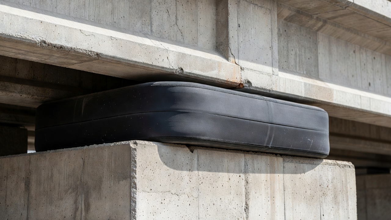
Neoprene Bearing Pad Design
Plain neoprene bearing pads — also called unreinforced elastomeric bearing pads — consist of a solid rectangular block of neoprene rubber used under bridge girders and beams to accommodate small movements and rotations while distributing vertical loads. These pads are specified for structures with relatively low vertical loads, limited movement requirements, and where the bearing is accessible for inspection and replacement. Plain pads function by compressing vertically under load and shearing horizontally to accommodate thermal expansion and contraction of the bridge superstructure. The design of plain neoprene bearing pads follows the provisions of AASHTO LRFD Bridge Design Specifications, Section 14.7.5, and AASHTO M251.
The vertical load capacity of a plain neoprene bearing pad is governed by the allowable compressive stress, which is limited to prevent excessive bulging and creep. AASHTO LRFD Section 14.7.5.3.2 limits the average compressive stress in plain elastomeric pads to 1,000 psi (6.9 MPa) for bearings subjected to combined dead load and live load, with a further reduction to 800 psi (5.5 MPa) when only dead load plus a portion of live load is considered. The shape factor (S) of a plain bearing pad — defined as the ratio of the loaded area to the area free to bulge — controls the compressive stiffness. For a rectangular pad of width W, length L, and total elastomer thickness T, the shape factor is calculated as:
S = (W × L) / (2 × T × (W + L))
A higher shape factor indicates greater restraint against lateral bulging and therefore higher compressive stiffness. AASHTO M251 requires that the shape factor for plain bearing pads be at least 3.0 for the pad to function effectively. The thickness of plain pads typically ranges from 1/4 inch (6 mm) to 2 inches (51 mm), with thicker pads providing greater movement capacity but lower vertical stiffness. The horizontal movement capacity of a plain pad is limited by the shear strain in the elastomer, which AASHTO limits to a maximum of 50 percent of the elastomer thickness at the service limit state. This means a 1-inch-thick plain pad can accommodate up to 0.5 inches (13 mm) of horizontal movement from thermal expansion, creep, and shrinkage.
Design criteria for plain pad thickness are established by the movement requirements. AASHTO LRFD Section 14.7.5.3.4 requires that the total elastomer thickness (T) satisfy:
T ≥ 2 × Δₛ
where Δₛ is the maximum horizontal movement at the bearing under the service limit state. This ensures that the shear strain γ = Δₛ/T does not exceed 0.50 (50 percent). The compressive deflection of plain pads is limited to 7 percent of the pad thickness under dead load plus a portion of live load, and 10 percent under all loads combined. Excessive compressive deflection indicates that the pad is overstressed or that the elastomer compound has insufficient hardness.
Plain pad instability is a design concern for thick, narrow pads. AASHTO LRFD Section 14.7.5.3.5 provides a stability requirement based on the pad’s slenderness ratio. The pad must satisfy:
T ≤ (W/3) or T ≤ (L/3)
for the pad to be considered stable against buckling under vertical load. If this condition is not met, the allowable compressive stress must be reduced using a stability reduction factor. In practice, most plain bridge bearing pads have a width-to-thickness ratio of at least 5:1 to ensure stability and prevent rollover under combined vertical and horizontal loads.
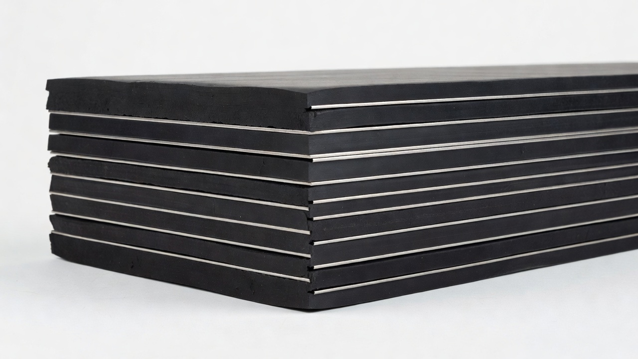
Steel-laminated elastomeric bearings use alternating layers of neoprene vulcanized to thin steel shim plates to dramatically increase vertical load capacity while preserving horizontal flexibility. The steel laminations prevent the lateral bulging of the elastomer under vertical compression, effectively confining the rubber and increasing its compressive stiffness. The design of laminated bearings is governed by AASHTO LRFD Section 14.7.6 and AASHTO M251.
Each internal elastomer layer in a laminated bearing acts as an individual plain pad restrained by the steel shims on its top and bottom faces. The shape factor for each individual elastomer layer in a laminated bearing is calculated using the same formula as for plain pads but using the thickness of the individual layer (Tᵢ) rather than the total pad thickness. AASHTO requires that the shape factor for each internal layer be at least 5.0, and the shape factor for the top and bottom cover layers (which have only one bonded face) be at least 3.0. The individual layer thickness is typically 3/8 inch (9.5 mm) to 1/2 inch (12.7 mm), with 1/2 inch being the most common. Thinner layers produce higher shape factors and higher compressive stiffness but increase manufacturing cost and reduce movement capacity.
The allowable compressive stress in laminated bearings is substantially higher than in plain pads. AASHTO LRFD Section 14.7.6.3.2 limits the average compressive stress to 1,200 psi (8.3 MPa) for bearings that are not subject to rotation, and 1,500 psi (10.3 MPa) for bearings that are free to rotate (pin-ended or rocker-type connections). The higher allowable stress for rotation-free bearings reflects the more uniform stress distribution that occurs when the bearing is free to accommodate end rotation through non-uniform compression of the elastomer layers.
Steel-Laminated Elastomeric Bearings
Steel-laminated elastomeric bearings — also referred to as laminated elastomeric bearings or reinforced elastomeric bearings — are the most widely used type of bridge bearing in modern highway construction. These bearings consist of multiple layers of neoprene rubber bonded through vulcanization to internal steel reinforcing plates (shims). The steel laminations are typically manufactured from hot-rolled carbon steel sheet conforming to ASTM A36 or A1011, with a minimum thickness of 14 gauge (0.075 inches, 1.9 mm) and a maximum thickness of 1/8 inch (3.2 mm) per AASHTO M251. The steel shims are fully encapsulated by the neoprene — the rubber extends around the edges of each shim with a minimum edge cover of 1/8 inch (3 mm) to prevent corrosion of the steel.
The structural mechanics of a laminated bearing are fundamentally different from a plain pad. Under vertical compression, the neoprene layers attempt to bulge laterally (Poisson effect). The steel shims, which are much stiffer than the rubber in the plane of the shim, restrain this lateral bulging. This restraint creates a state of triaxial compression in the elastomer — compression in the vertical direction plus biaxial compression in the horizontal plane — which dramatically increases the effective compressive modulus of the rubber. A laminated bearing with internal layers having a shape factor of 7.5 can have a compressive modulus 50 to 100 times greater than the shear modulus of the same rubber compound. This allows laminated bearings to support very high vertical loads while maintaining the low shear stiffness required for horizontal movement accommodation.
Horizontal movement is accommodated through shear deformation of the entire bearing — all elastomer layers shear in parallel, with the steel shims remaining parallel to each other as the top and bottom of the bearing translate relative to each other. The shear stiffness of a laminated bearing is the same as for a plain pad of the same total elastomer thickness, because the steel shims do not resist shear. The total shear deformation capacity is the sum of the shear capacities of all individual elastomer layers. AASHTO LRFD Section 14.7.6.3.4 limits the shear strain to 0.50 (50 percent) under service loads, and 0.70 (70 percent) under extreme event loads such as earthquakes.
Rotation of the bridge superstructure at the bearing is accommodated through non-uniform compression of the individual elastomer layers — the rubber compresses more on one side of the bearing than the other, allowing the top and bottom surfaces of the bearing to rotate relative to each other. The rotation capacity of a laminated bearing is determined by the number and thickness of the internal elastomer layers. AASHTO limits the rotation-induced compressive strain at the edge of any internal layer to 50 percent of the layer thickness, which effectively limits the maximum rotation that can be accommodated by the bearing. The rotation capacity expressed in radians is approximately:
θ_max = 0.5 × n × Tᵢ / (L/2)
where n is the number of internal elastomer layers, Tᵢ is the individual layer thickness, and L is the bearing length in the direction of rotation.
Stability against buckling is a critical design consideration for laminated bearings. AASHTO LRFD Section 14.7.6.3.5 provides a stability criterion based on the bearing’s slenderness ratio and shape factor. The critical buckling load of a laminated bearing is a function of the shear modulus, the compressive modulus (determined by the shape factor), and the bearing’s overall dimensions. AASHTO requires that the applied compressive stress not exceed the critical buckling stress divided by a safety factor of 3.0. For typical bridge bearing proportions — where the overall height is less than the smallest plan dimension — stability is not a governing design condition.
Cover layers are provided on the top and bottom of laminated bearings to protect the outermost steel shims from corrosion and to provide a uniform contact surface with the bridge girder and substructure. AASHTO M251 requires a minimum cover layer thickness of 1/4 inch (6.4 mm) on the top and bottom faces. These cover layers are not bonded to steel on their outer faces, so their shape factor is calculated differently — they have a shape factor half that of an equivalent bonded internal layer because they can bulge freely from the unbonded outer face.
Manufacturing tolerances for laminated bearings are specified in AASHTO M251. The overall height tolerance is ±1/16 inch (1.6 mm) for bearings up to 2 inches (51 mm) thick and ±3/32 inch (2.4 mm) for thicker bearings. The plan dimension tolerance is ±1/8 inch (3.2 mm) for bearings up to 12 inches (305 mm) in each dimension and ±3/16 inch (4.8 mm) for larger bearings. The steel shims must be flat within 1/16 inch over the shim length, and the finished bearing must show no visible defects including blisters, porosity, or surface cracks.
Neoprene Deterioration Mechanisms
Neoprene in bridge bearing and joint seal applications undergoes several distinct deterioration mechanisms over its service life. Understanding these mechanisms is essential for bridge inspectors to accurately assess component condition and predict remaining service life. The five primary deterioration modes affecting neoprene bridge components are ozone cracking, stiffening (hardening) , permanent set (compression set) , delamination, and chemical degradation.
Ozone cracking is the most characteristic and visually distinctive deterioration mode for neoprene bridge components. Ozone (O₃) is a highly reactive allotrope of oxygen present in the lower atmosphere at concentrations ranging from 0.01 to 0.50 parts per million (ppm). Ozone attacks unsaturated polymer chains — specifically the carbon-carbon double bonds remaining in the polychloroprene backbone after vulcanization. The reaction mechanism involves ozone molecules inserting into the double bond structure and cleaving the polymer chain, creating chain scission. The scission sites then propagate as surface cracks oriented perpendicular to the direction of maximum tensile stress in the rubber.
The characteristics of ozone cracking in neoprene are distinctive: cracks are fine and sharp-edged, typically 0.1 to 1.0 mm in width, and they run in straight or slightly curved lines perpendicular to the direction of tensile stress. In bridge bearings, the tensile stress at the bearing surface is caused by the Poisson effect — as the bearing is compressed vertically, the material attempts to expand laterally, creating tensile strains in the horizontal direction. The resulting ozone cracks therefore run vertically on the side faces of bridge bearing pads, particularly near the center of the side face where lateral expansion is maximum.
The depth and density of ozone cracking progress with exposure time. In the early stage (typically 3 to 10 years of service in temperate climates), surface cracks are visible only under close visual inspection with a magnification aid and are less than 1 mm deep. In the moderate stage (10 to 20 years), cracks become visible to the naked eye and may penetrate 2 to 5 mm into the bearing section. In the advanced stage (20+ years), cracks can penetrate more than 10 mm deep, and multiple intersecting crack systems develop on the bearing surfaces. At this stage, cracks may expose the steel shims in laminated bearings, creating a corrosion pathway for moisture to reach the reinforcing steel. The FHWA report on bridge bearing inspection criteria identifies cracking depth exceeding 6 mm (1/4 inch) as a critical finding requiring evaluation for replacement.
Stiffening (hardening) of neoprene occurs through continued crosslinking of polymer chains during service life. The vulcanization process initially establishes a crosslink network, but crosslinking continues slowly over time through residual curing agents and thermal activation. Additional crosslinking through thermal oxidation creates new carbon-carbon and carbon-oxygen crosslinks between adjacent polymer chains, progressively reducing the molecular mobility of the rubber. This manifests as a measurable increase in Shore A durometer hardness and shear modulus. FHWA research indicates that neoprene bridge bearings can experience a 5 to 15 point increase in Shore A hardness over 20 to 30 years of service.
The effects of stiffening on bearing performance are significant. A stiffened bearing has increased compressive modulus, which means it transfers higher forces to the substructure for a given thermal movement and imposes greater restraint on the bridge superstructure. Increased stiffness can lead to higher stresses in the bridge girders and substructure connections that were not accounted for in the original design. A bearing that originally had a shear modulus of 0.90 MPa (130 psi) may develop a shear modulus exceeding 1.55 MPa (225 psi) after extensive stiffening, potentially doubling the horizontal forces transmitted to the substructure at full design movement.
Permanent set — also called compression set — is the irreversible reduction in bearing thickness due to the elastic recovery of the polymer not being complete after release of compressive load. Compression set occurs because polymer chains under sustained compression undergo viscoelastic relaxation — the chain segments gradually rearrange to accommodate the compressed state, reducing the driving force for recovery when the load is released. AASHTO M251 limits compression set to 35 percent maximum (measured after 22 hours at 212°F per ASTM D395 Method B) for new material, but in-service compression set can exceed this value over time as the polymer continues to age.
The consequences of excessive permanent set include loss of vertical load distribution — a bearing that has compressed permanently may no longer be in full contact with the bridge girder or substructure, creating stress concentrations at contact points. For bridge bearings supporting multi-girder spans, differential compression set between bearings on adjacent girders can transfer load from one girder to another, overstressing the more heavily loaded members. Permanent set exceeding 10 percent of the original bearing thickness, particularly when combined with visible cracking, is generally considered a replacement threshold.
Delamination refers to the separation of the neoprene rubber from the steel shim plates in laminated bearings. This failure mode is caused by loss of the adhesive bond between rubber and steel, which is established during the vulcanization process through a combination of chemical bonding (sulfur crosslinks between rubber and the brass-plated or zinc-plated steel surface) and mechanical interlocking at the roughened steel surface. Delamination can be initiated by corrosion of the steel shims (which disrupts the bonded interface), by excessive cyclic shear strains that exceed the bond strength, or by manufacturing defects where the bond was not properly established.
Detection of delamination during visual inspection is challenging because the outer rubber cover layer may remain intact even when internal bond failure has occurred. Signs of possible delamination include localized bulging or blistering of the bearing side surfaces, visible gaps between rubber and steel at cut edges (though cut edges are not typically present in finished bearings), and audible hollow sounds when tapping the bearing with an inspection hammer — a technique borrowed from concrete sounding. Advanced inspection methods such as ultrasonic testing (UT) or infrared thermography can detect internal delamination that is not visible on the surface. Any confirmed delamination is grounds for immediate replacement, as the bearing has lost its structural integrity and can no longer reliably transfer vertical load.
Chemical degradation encompasses several additional deterioration mechanisms. Antiozonant depletion occurs as the chemical antiozonants (typically p-phenylenediamine derivatives added to the neoprene compound during formulation) are consumed through reaction with ozone or leached from the surface by rainwater. As antiozonant levels decline, the rubber becomes increasingly vulnerable to ozone attack. Extractable material loss involves the gradual depletion of plasticizers, processing oils, and other non-polymer constituents that were added to control the compound’s hardness and processing characteristics. Hydrolysis — chemical breakdown of the polymer by water — is relatively rare in neoprene but can occur under conditions of continuous immersion in water at elevated temperatures.
Neoprene Joint Seals
Neoprene is the predominant material for bridge expansion joint seals, specifically in preformed compression seals and strip seal expansion joint systems. These seals are installed in the gap between adjacent bridge deck segments to accommodate thermal expansion and contraction while preventing water, deicing chemicals, and debris from reaching the bridge substructure and bearings below. The performance requirements for neoprene joint seals are specified in AASHTO M297 (Standard Specification for Preformed Elastomeric Bridge Joint Seals) and ASTM D2628 (Standard Specification for Preformed Polychloroprene Elastomeric Joint Seals for Bridges).
Preformed compression seals — also called compression joint seals — are extruded neoprene profiles with a complex cross-section design featuring multiple internal voids or webs. These seals are installed by compressing them into a properly prepared joint recess. The seal is held in place by its own elastic recovery — the cross-section is oversized relative to the joint gap by 20 to 40 percent, so the seal exerts a continuous compressive force against the sidewalls of the joint recess. The internal web geometry is designed to provide a watertight barrier while allowing the seal to expand and contract as the joint gap changes with temperature. Common compression seal profiles include the dumbbell, multiple-web, and box-section designs, each engineered for specific movement ranges and installation conditions.
The installation process for compression seals requires precise joint preparation. The joint recess must have clean, parallel concrete faces with a surface smoothness such that irregularities do not exceed 1/8 inch (3 mm) in 10 feet (3 m). The joint is typically formed with a metal bulkhead during concrete placement or saw-cut to precise dimensions after the concrete has cured. A bonding adhesive — typically a two-component epoxy or polysulfide compound — is applied to the joint sidewalls immediately before seal installation to lock the seal in place and prevent water migration along the rubber-concrete interface. The seal is then compressed using a special installation tool (a roller or lever-operated compression tool) and inserted into the joint. The installation tool must be sized to compress the seal to between 50 and 70 percent of its free width for proper installation.
Movement capacity of compression seals is determined by the seal cross-section design and the degree of initial compression. For a typical 2-inch (51 mm) wide compression seal installed in a 1.5-inch (38 mm) wide joint gap, the movement capacity is approximately ±50 percent of the installed width, meaning the joint can open to 2.25 inches (57 mm) and close to 0.75 inches (19 mm). AASHTO M297 classifies compression seals by movement capability in categories from ±25 percent to ±75 percent of the installed width. The seal must be designed to function through the full range of thermal movements without losing contact with the joint sidewalls (which creates a leak path) and without extruding from the joint recess (which creates a traffic hazard).
Strip seal expansion joints — also called elastomeric strip seals — represent a more advanced joint sealing technology that provides greater movement capacity and improved watertightness. A strip seal system consists of a neoprene extruded profile with a central bulbous or folding section that accommodates movement, flanked by anchorage bulbs that are mechanically locked into steel edge rails. The steel edge rails are cast into the concrete deck on each side of the expansion gap. The neoprene strip seal is designed to be replaceable without disturbing the concrete — the anchorage bulbs are pressed into the steel rails and can be extracted using a special removal tool when replacement is needed.
Strip seals provide movement capacities ranging from 2 inches (51 mm) to 6 inches (152 mm) or more, depending on the profile design and the spacing between steel edge rails. The neoprene compound used in strip seals must meet the same material requirements as compression seals per AASHTO M297, with additional requirements for the anchorage pullout resistance — the force required to remove the seal from the steel rail must exceed 50 pounds per linear inch (87.5 N/cm) to ensure the seal remains locked in place under traffic-induced vibrations and thermal cycling.
Deterioration of neoprene joint seals follows the same mechanisms as described for bearings — ozone cracking, stiffening, and permanent set — but with several application-specific differences. Joint seals are exposed to direct UV radiation (in open-deck bridges), vehicular tire contact (which causes abrasion and cyclic compression), deicing chemical spray, and abrasive debris (sand, gravel, salt particles abraded by traffic). Ozone cracking in compression seals typically initiates at the exterior face of the seal at points of maximum tensile strain — usually at the corners of the cross-section where the geometry creates strain concentrations.
Joint seal adhesion loss — separation of the seal from the concrete joint sidewall — is a common failure mode distinct from the material deterioration mechanisms. Adhesion loss is caused by:
Inadequate surface preparation during installation (dirty or damp concrete surfaces)
Freeze-thaw cycling at the rubber-concrete interface
Traffic-induced vibration that fatigues the adhesive bond
Seal stiffening that increases the force at the adhesive interface beyond the bond strength
When a compression seal loses adhesion on one side, it can become partially dislodged from the joint, creating a tripping hazard for pedestrians, a source of tire impact damage for vehicles, and an open pathway for water to reach the bridge substructure.
Inspection of Neoprene Components
Bridge inspection of neoprene components follows the general framework established by the National Bridge Inspection Standards (NBIS) (23 CFR 650, Subpart C) and the FHWA Bridge Inspector’s Reference Manual (BIRM) (Publication No. FHWA NHI 12-049). Neoprene bearing and joint seal condition assessment is part of the routine (24-month) inspection cycle for all highway bridges in the United States. The inspection protocol for neoprene components includes visual inspection, measurement of deterioration, functional assessment, and documentation of findings using standard condition rating systems.
Visual inspection begins with observation of the bearing or joint seal from a distance to assess overall appearance and alignment. The inspector then moves to close range (within arm’s reach) to examine the neoprene surfaces for deterioration. Key observations include:
Surface cracking patterns — orientation, density, depth, and distribution of cracks. Cracks are categorized as surface crazing (fine network of superficial cracks less than 1 mm deep), moderate cracking (individual cracks 1-3 mm deep covering less than 50 percent of the surface), and severe cracking (cracks exceeding 3 mm depth or covering more than 50 percent of the surface).
Hardness assessment — performed using a Shore A durometer pressed against the neoprene surface. The inspector compares measured hardness to the original specification (typically 60 ± 5 Shore A). An increase of more than 10 points from the original value indicates significant stiffening.
Permanent set measurement — the residual thickness of the bearing compared to its original specified thickness. For bearings where the original thickness is not documented, the inspector compares the bearing to adjacent bearings on the same bridge or to unused bearings of the same type. Thickness is measured using a steel ruler or caliper at the center of each side face, and the minimum measurement is recorded.
Bulging and delamination check — visual examination for localized bulging on the bearing side faces, which can indicate internal delamination. The inspector also taps the bearing side surfaces with a plastic or rubber mallet to detect hollow sounds suggestive of bond failure.
Shear deformation measurement is a critical functional assessment. The inspector measures the horizontal offset between the top and bottom of the bearing using a ruler or measuring tape. This offset is compared to the total elastomer thickness to determine the shear strain. AASHTO limits shear strain to 50 percent under service conditions, so a bearing with a total elastomer thickness of 3 inches (76 mm) should not exhibit more than 1.5 inches (38 mm) of horizontal offset. Shear deformation should be measured at the bridge temperature at the time of inspection, and the measured value should be compared to the calculated thermal movement based on the temperature at the time relative to the installation temperature. Excessive shear deformation — particularly when observed in the absence of corresponding thermal movement — may indicate bearing slippage or an unseated condition.
Rotation assessment involves measuring the angle between the top and bottom surfaces of the bearing. Excessive rotation — where the bearing top surface is not parallel to the bottom surface by more than the design rotation capacity — may indicate that the bearing is not properly distributing the end rotation of the bridge girder. This can be caused by overloading, bearing stiffening (which concentrates rotation at fewer elastomer layers), or loss of bearing material through deterioration.
Compression seal inspection focuses on the following conditions:
Seal extrusion — the seal protruding above the deck surface, which creates a tripping hazard and indicates that the joint gap has closed beyond the seal’s compression capacity.
Seal sagging — the seal depressed below the deck surface, which indicates that the joint has opened beyond the seal’s extension capacity or that the seal has experienced compression set.
Adhesion loss — the seal separated from the joint sidewall on one or both sides, visible as a gap between the rubber and the concrete.
Tearing or puncture — local damage from tire contact, debris impact, or snowplow blade contact.
Debris accumulation — gravel, sand, or vegetation trapped in the joint, which restricts seal movement and can cause localized overstressing.
Documentation of neoprene component condition follows the CoRe (Commonly Recognized) element coding system used in the FHWA’s National Bridge Inventory (NBI) structure inventory and appraisal system. Element 321 (Elastomeric Bearing) and Element 323 (Elastomeric Joint Seal) are the standard coding elements for neoprene bridge components. Each element is assigned a condition state from 1 (good condition, no deterioration) through 5 (severe condition, replacement required) with specific quantitative criteria defining the boundary between condition states for each deterioration type.
The table below summarizes the condition state criteria for elastomeric bearings from the AASHTO Manual for Bridge Element Inspection (MBEI):
Condition State
Cracking
Permanent Set
Shear Deformation
Stiffening
1 (Good)
None or superficial
<5% of original thickness
<25% of elastomer thickness
Within original spec
2 (Fair)
Surface crazing, <3 mm depth
5-10% of original thickness
25-35% of elastomer thickness
<10 pt hardness increase
3 (Poor)
Moderate cracking 3-6 mm deep
10-15% of original thickness
35-50% of elastomer thickness
10-20 pt hardness increase
4 (Severe)
Deep cracking >6 mm deep
15-20% of original thickness
>50% (with cracking)
>20 pt hardness increase
5 (Critical)
Full-depth cracking or steel exposed
>20% of original thickness
>75% or impending rollover
Bearing no longer functional
Replacement Criteria
The decision to replace neoprene bridge bearings or joint seals is based on quantitative condition thresholds combined with engineering judgment regarding the component’s ability to continue serving its intended function. The replacement criteria are derived from AASHTO LRFD Bridge Design Specifications, FHWA guidance, and state DOT maintenance manuals.
Replacement criteria for neoprene bearings include the following thresholds, any of which may trigger replacement:
Crack depth exceeding 6 mm (1/4 inch) in a primary load-bearing area, or crack penetration exceeding 50 percent of the cover layer thickness in laminated bearings. This threshold corresponds to Condition State 4 in the AASHTO MBEI and indicates that the structural integrity of the bearing may be compromised.
Crack width exceeding 6 mm (1/4 inch) at the bearing surface, regardless of depth. Wide cracks indicate advanced ozone degradation and may allow moisture and debris to penetrate into the bearing interior.
Cracks extending across 50 percent or more of the bearing width in any direction. This indicates that the deterioration is systemically distributed across the bearing rather than localized.
Permanent set exceeding 10 percent of the original bearing thickness (Condition State 3 boundary) when combined with visible cracking or stiffening. Bearings with greater than 10 percent permanent set but no other deterioration may remain in service subject to increased inspection frequency.
Permanent set exceeding 15 percent of original thickness regardless of other deterioration. At this level, the bearing has lost sufficient thickness that the distribution of vertical load is compromised, and stress concentrations at contact points may exceed allowable limits.
Shear deformation exceeding 50 percent of the total elastomer thickness at the service temperature. The movement capacity of the bearing has been exceeded, and further movement could result in the bearing rolling over or slipping out of its seating.
Shear deformation exceeding 75 percent of total elastomer thickness at any temperature — immediate replacement required, as the bearing is at risk of catastrophic failure (rollover or extrusion).
Delamination detected at any location within the bearing — immediate replacement required. A delaminated bearing has lost the composite action between rubber and steel and cannot reliably transfer vertical load.
Exposed steel shims in laminated bearings — the protective rubber cover has been breached, and corrosion of the steel shims will accelerate. The bearing must be replaced to prevent shim corrosion from propagating into adjacent bonded areas.
Bulging or localized deformation of the bearing side face exceeding 10 percent of the bearing plan dimension — indicative of internal delamination or rubber deterioration requiring further investigation.
Loss of bearing contact — any gap between the bearing and the bridge girver or between the bearing and the substructure — requires immediate evaluation. Loss of contact indicates that the bearing is no longer providing uniform support to the superstructure.
Replacement criteria for neoprene compression joint seals include:
Adhesion loss on one side extending more than 10 percent of the joint length — the seal is no longer watertight and partial replacement or resealing is required.
Adhesion loss on both sides — the seal can become dislodged and create a traffic hazard. Immediate replacement of the affected section is required.
Seal extrusion above the deck surface exceeding 1/8 inch (3 mm) — creates a tripping hazard for pedestrians and a tire impact source for vehicles. The joint gap has closed beyond the seal’s design range, or the seal has experienced compression set.
Seal depression below the deck surface exceeding 1/4 inch (6 mm) — the joint has opened beyond the seal’s movement capacity, or the seal has experienced tension set. Debris accumulation in the depressed area restricts movement and may cause water ponding.
Cracking of the seal material — any visible crack through the full thickness of the seal wall (through-cracking) requires immediate replacement, as the watertight barrier has been breached.
Tearing of the seal web (the internal void walls in multi-web compression seals) — the seal has experienced tensile overstress and has lost structural continuity.
Puncture or abrasion damage exposing internal voids — the seal can no longer maintain compression against the joint walls.
Stiffening resulting in hardness increase of more than 20 Shore A points from the original specification — the seal can no longer maintain adequate compression against the joint walls to ensure watertightness.
Urgency classification for bearing replacement follows three categories:
Emergency replacement (within days to weeks): bearings at risk of imminent failure, including bearings with shear deformation exceeding 75 percent, confirmed delamination, or loss of contact with the superstructure.
Scheduled replacement (within 6 to 12 months): bearings with Condition State 4 deterioration (deep cracking >6 mm, permanent set >15 percent, cracking combined with stiffening).
Programmed replacement (within 1 to 5 years): bearings with Condition State 3 deterioration nearing the escalation thresholds, requiring increased inspection frequency (annually instead of biennially) until replacement is completed.
Specifications
The material, design, and testing specifications for neoprene in bridge bearings and joint seals are defined by two primary standards in the United States: AASHTO M251 (Standard Specification for Plain and Laminated Elastomeric Bridge Bearings) and ASTM D4014 (Standard Specification for Plain and Steel-Laminated Elastomeric Bearings for Bridges). These specifications establish the requirements for neoprene compound formulation, physical properties, dimensional tolerances, steel shim requirements, bond integrity, and performance testing.
AASHTO M251, developed by the American Association of State Highway and Transportation Officials, is the governing specification for elastomeric bridge bearings used on the National Highway System and on all federal-aid highway projects. The specification covers two types of neoprene compounds: Type I (chloroprene polymer with a minimum 50 percent polychloroprene content) and Type II (natural rubber or blends). For bridge bearings, Type I (neoprene) is the default specification, with Type II (natural rubber) permitted only when specified by the contract documents. AASHTO M251 requires that neoprene compound samples meet the following minimum physical property requirements after standard vulcanization:
Property
Requirement
Test Method
Tensile Strength, min (original)
15.0 MPa (2,175 psi)
ASTM D412, Die C
Tensile Strength after 70 h at 212°F (100°C)
min 12.5 MPa (1,800 psi)
ASTM D573
Elongation at Break, min (original)
400%
ASTM D412, Die C
Elongation after 70 h at 212°F (100°C)
min 350%
ASTM D573
Compression Set, max (22 h at 212°F)
35%
ASTM D395, Method B
Ozone Resistance (50 pphm, 20% strain, 168 h)
No cracks
ASTM D1149
Low-Temperature Brittleness
No failure at -40°F (-40°C)
ASTM D2137, Method B
Shore A Hardness
60 ± 5
ASTM D2240
ASTM D4014 provides specification requirements that are substantively similar to AASHTO M251 but is the standard recognized outside the federal-aid highway system. ASTM D4014 defines the same neoprene compound requirements with minor variations in test method references. The specification covers both plain pads and steel-laminated bearings, with separate requirements for:
Neoprene compound — physical properties as shown in the table above
Edge cover — minimum 1/8 inch (3 mm) rubber coverage over all steel shim edges
Bond strength — no separation between rubber and steel when tested per ASTM D429, Method A
AASHTO M297 (Standard Specification for Preformed Elastomeric Bridge Joint Seals) governs neoprene compression seals used in bridge expansion joints. The requirements parallel those of AASHTO M251 but are adjusted for the specific service conditions of joint seals:
Hardness — 55 ± 5 Shore A (softer than bearing compounds for better conformability to joint surfaces)
Tensile strength — minimum 12.0 MPa (1,740 psi)
Elongation — minimum 350 percent
Compression set — maximum 40 percent (less critical for joint seals than for bearings)
Heat aging — tensile strength retention minimum 80 percent after 70 hours at 212°F (100°C)
Ozone resistance — no cracking after 168 hours at 50 pphm ozone, 20 percent strain
Low-temperature compound specifications address bridges in cold climate regions. AASHTO M251 permits the use of special low-temperature neoprene compounds for projects where the design temperature falls below -30°F (-34°C). These compounds are formulated with reduced sulfur content and specialized plasticizers to improve low-temperature flexibility without significantly compromising ozone resistance or other properties. Low-temperature compounds must meet all standard physical property requirements plus additional low-temperature testing:
Brittleness temperature — no failure at -55°F (-48°C) per ASTM D2137, Method B (compared to -40°F for standard compounds)
Low-temperature stiffness — shear modulus increase limited to 3 times the room-temperature value at the minimum design temperature
Gehman low-temperature stiffness — torsional stiffness test per ASTM D1053 showing T₁₀₀ (temperature at which modulus is 100 times the room-temperature value) below the minimum design temperature
Testing and quality assurance requirements in AASHTO M251 and ASTM D4014 include:
Sample testing — each production batch of neoprene compound must be tested for physical properties before bearing fabrication
Full-scale testing — prototype bearings for projects exceeding specified size thresholds must undergo full-scale compression and shear testing to verify performance
Factory inspection — during fabrication, random samples are taken from production bearings for bond testing and dimensional verification
Certification — the bearing manufacturer must provide a certificate of compliance stating that the bearings meet all specification requirements
International standards for neoprene bridge bearings include:
EN 1337-3 (European Standard for Structural Bearings — Elastomeric Bearings) — applies across European Union member states and specifies similar material requirements with minor differences in test methods and acceptance criteria
ISO 6446 (Rubber Products — Bridge Bearings — Specification for Rubber Materials) — international standard providing material specification guidance for bridge bearing elastomers
BS 5400-9.2 (British Standard for Steel, Concrete and Composite Bridges — Bridge Bearings) — widely adopted in Commonwealth nations
The specifications require that neoprene bridge components include permanent identification markings indicating: manufacturer name, compound type, date of manufacture (month and year), and lot number. These markings must be legible for the intended service life of the component, typically achieved through molded-in raised lettering rather than ink stamps or labels that may degrade.
+++
Frequently Asked Questions
Neoprene, chemically polychloroprene, is a synthetic elastomer invented by DuPont in 1930. It is used in bridge bearings and joint seals because of its exceptional resistance to ozone, ultraviolet radiation, weathering, oils, greases, and moderate temperature extremes. Unlike natural rubber, neoprene maintains its elastic properties over decades of outdoor exposure and can be compounded to meet specific hardness, shear modulus, and compression set requirements defined in AASHTO M251 and ASTM D4014.
Plain neoprene bearing pads are solid rectangular blocks of neoprene rubber used under low-load conditions typically below 1,000 psi (6.9 MPa). Steel-laminated elastomeric bearings consist of alternating layers of neoprene bonded to thin steel shim plates (typically 14 to 16 gauge) through a vulcanization process. The steel laminations restrain lateral bulging of the rubber under vertical compression, allowing the bearing to support significantly higher loads — up to 1,500 psi (10.3 MPa) or more — while still accommodating horizontal movement through shear deformation and rotation through non-uniform compression.
Ozone cracking occurs when atmospheric ozone (O₃) attacks neoprene polymer chains under tensile stress. Ozone molecules react with unsaturated carbon-carbon double bonds remaining in the polymer backbone, breaking the molecular chains and producing surface cracks oriented perpendicular to the direction of tensile stress. These cracks initiate at stress concentration points such as surface irregularities, and propagate progressively. Unlike thermal oxidation which causes uniform stiffening, ozone cracking creates localized fissures that can penetrate deep into the bearing section, potentially exposing steel laminations to moisture and corrosion.
AASHTO M251 is the primary specification for plain and laminated elastomeric bridge bearings in the United States, covering material properties, dimensional tolerances, and performance requirements. ASTM D4014 provides the equivalent standard specification for plain and steel-laminated elastomeric bearings for bridges. These specifications define neoprene compound requirements including minimum tensile strength (15.0 MPa after aging in ASTM D4014), minimum elongation at break (350 percent), maximum compression set (35 percent), and Shore A durometer hardness range (50 to 70). They also specify steel shim material (ASTM A36 or equivalent), minimum shim thickness (14 gauge, 1.9 mm), and bond strength between rubber and steel.
Neoprene bridge bearings should be replaced when: cracks exceed 6 mm (1/4 inch) in width, 5 percent of the bearing thickness in depth, or extend 50 percent across the bearing width; permanent set (height loss) exceeds 10 percent of the original thickness combined with visible cracking; delamination between rubber and steel shims is detected through visual bulging or ultrasonic testing; shear deformation exceeds 50 percent of the total elastomer thickness at the design temperature; or the bearing shows evidence of 360-degree rollover or complete loss of vertical load capacity.
Neoprene significantly outperforms natural rubber in resistance to ozone cracking, weathering, UV degradation, oil and grease exposure, and flame resistance. Natural rubber has higher tensile strength (25-30 MPa vs 17-20 MPa for neoprene), better low-temperature flexibility (glass transition temperature around -60°C vs -45°C for neoprene), and lower hysteresis (less heat buildup under cyclic loading). However, natural rubber undergoes rapid degradation in outdoor bridge environments where ozone, sunlight, and road salts are present, making neoprene the preferred material for all bridge bearing and joint seal applications despite its higher material cost.
Improve Your Bridge Inspection Program
Implement comprehensive bridge component condition assessment including neoprene bearing and joint seal evaluations. Protect your infrastructure investments with professional inspection standards and data-driven maintenance planning.
Preformed compression seals are pre-compressed elastomeric (neoprene/polychloroprene) strips inserted into concrete pavement joints that expand against the join...
Bridge expansion joints are structural devices that accommodate thermal movement, creep, shrinkage, and live-load deflection between spans or between the deck a...
Bridge bearings are critical load-transfer devices at abutments and piers that transmit superstructure forces to the substructure while accommodating thermal mo...
28 min read
Bridge components
Bridge inspection
+3
Cookie Consent We use cookies to enhance your browsing experience and analyze our traffic. See our privacy policy.