Impact-Echo Testing
Impact-Echo is a stress-wave nondestructive testing method where a short-duration mechanical impact on a concrete surface generates stress waves that reflect fr...
32 min read
Non-Destructive Testing
Concrete NDT
+4
Non-Destructive Testing (NDT) encompasses methods to evaluate material properties, detect defects, and assess structural condition without causing damage. For infrastructure inspection, NDT includes ultrasonic testing, impact-echo, ground-penetrating radar, infrared thermography, half-cell potential, rebound hammer, and visual/imaging methods.
Non-Destructive Testing (NDT), also referred to as non-destructive evaluation (NDE) or non-destructive inspection (NDI), is a multidisciplinary set of analysis techniques used across engineering to evaluate the properties, integrity, and condition of materials, components, or structures without causing permanent damage. The fundamental premise of NDT is that the inspection process must leave the tested object fully functional and serviceable. This distinguishes NDT from destructive testing methods that intentionally compromise or destroy specimens to measure properties.

In the context of infrastructure inspection, NDT encompasses a specific subset of methods adapted for civil engineering materials — primarily concrete, asphalt, steel reinforcement, masonry, and timber. The scope spans from simple visual observation with minimal equipment to sophisticated tomographic imaging using phased-array ultrasonic transducers. According to the International Atomic Energy Agency (IAEA) Training Course Series No. 17, the most commonly applied NDT methods for concrete structures include ultrasonic pulse velocity testing, impact-echo, ground-penetrating radar (GPR), infrared thermography, half-cell electrical potential measurement, Schmidt rebound hammer testing, radiography, and visual inspection.
The International Atomic Energy Agency (IAEA) defines NDT of concrete as essential for evaluating in-situ concrete quality, detecting hidden defects, assessing structural integrity, and monitoring deterioration over time. The American Concrete Institute (ACI) Committee 228 — Nondestructive Test Methods for Evaluation of Concrete in Structures — publishes the comprehensive guide ACI 228.2R-13, which classifies NDT methods by the material property they measure: strength, uniformity, thickness, reinforcement condition, corrosion potential, or presence of defects.
NDT serves critical functions across the entire infrastructure lifecycle: quality control during construction (verifying proper placement, consolidation, and curing), acceptance testing (confirming design specifications are met), condition assessment of existing structures (evaluating deterioration for maintenance planning), and structural health monitoring (tracking property changes over time to predict remaining service life).
The global NDT market for infrastructure is driven by aging asset inventories, increased awareness of life-cycle cost benefits, regulatory mandates, and technological advances that improve detection capabilities while reducing inspection time and cost. Reactive repair costs typically run 3 to 5 times higher than planned, NDT-driven maintenance interventions, making NDT a financially compelling strategy for asset owners.
Understanding the distinction between NDT and destructive testing (DT) is fundamental to selecting the appropriate evaluation approach for infrastructure assets. Both methodologies aim to characterize material properties or detect defects, but they operate on fundamentally different principles with distinct trade-offs in accuracy, cost, and applicability.
Destructive testing subjects a material sample to stress, load, or environmental conditions until failure occurs. Common DT methods for concrete include compression testing of cylinders or cores (ASTM C39), flexural strength testing of beams (ASTM C78), split tensile testing (ASTM C496), and pullout testing (ASTM C900). The primary advantage of DT is that it provides direct, quantifiable measurements of material strength and behavior under controlled conditions. The results are unambiguous — a concrete cylinder crushed at 35 MPa has definitively reached its compressive strength.
However, DT has significant drawbacks for infrastructure assessment. First, it creates localized damage that requires repair. Cored holes in bridge decks must be patched, which introduces potential weak points and moisture intrusion pathways. Second, DT provides information only at the specific sampling location, not across the entire structure. Statistical sampling plans (ACI 214R) attempt to address this, but the data remains inherently discrete. Third, DT is impractical for repeated monitoring — you cannot core the same location multiple times to track deterioration progression. Fourth, DT requires traffic control for lane closures on bridges and pavements, adding cost and public inconvenience.
NDT, by contrast, enables repeated measurements at the same locations over time, allowing direct comparison of deterioration rates. NDT methods can be applied at hundreds or thousands of points across a structure, providing spatial mapping of properties and defect distribution. While NDT measurements are often indirect — correlating measured physical parameters (wave velocity, electrical potential, thermal contrast) to material properties through empirical relationships or theoretical models — they offer the critical advantage of preserving structural integrity.
| Aspect | Destructive Testing (DT) | Non-Destructive Testing (NDT) |
|---|---|---|
| Specimen integrity | Destroyed or damaged | Preserved |
| Measurement type | Direct (strength, modulus) | Indirect (correlated through models) |
| Sampling density | Low (10-50 cores per project) | High (thousands of data points) |
| Repeatability | Single use per location | Unlimited repeated measurements |
| Traffic impact | High (lane closures required) | Variable (some methods require full closure, others partial) |
| Cost per data point | High (sampling, testing, repair) | Low to moderate |
| Coverage | Discrete points | Continuous or grid mapping |
| Applicability to in-service structures | Limited (after construction) | Full (construction through decommissioning) |
For comprehensive infrastructure assessment, NDT and DT are complementary rather than competitive. A typical protocol involves NDT screening of the entire structure to identify anomalous areas, followed by limited destructive coring at representative locations to calibrate NDT results with direct strength data. This hybrid approach, recommended by ACI 228.2R-13 and the IAEA Guidebook, maximizes the spatial coverage of NDT while anchoring results to absolute material properties from DT.
Visual inspection (VT) is the most fundamental and widely practiced NDT method. It serves as the starting point for virtually every infrastructure assessment program and is specified as a mandatory element in most bridge and pavement inspection standards worldwide. Despite its apparent simplicity, visual inspection — when performed systematically by trained personnel — provides critical information about structural condition, deterioration mechanisms, and safety hazards.
According to the IAEA Guidebook on non-destructive testing of concrete structures, visual inspection involves systematic observation of accessible surfaces using natural or artificial light, aided by simple tools such as measuring tapes, calipers, crack microscopes (10x to 50x magnification), feeler gauges, plumb bobs, levels, and digital cameras. The inspector documents the type, location, extent, and severity of surface defects.
The National Bridge Inspection Standards (NBIS) in the United States require visual inspection as the primary method for routine bridge inspections conducted every 24 months. AASHTO Manual for Bridge Evaluation defines specific element-level condition states based on visual observations: cracking patterns, spalling, delamination indicators (hollow sound when tapped), efflorescence (white salt deposits indicating moisture transport), exposed reinforcement, corrosion staining, and surface disintegration.
What visual inspection reveals:
Limitations of visual inspection are well documented. Research by the Federal Highway Administration (FHWA) has shown that visual inspection alone detects only 40-60% of significant defects in bridge decks, particularly those that are subsurface (internal delamination, incipient corrosion, voids in grouted tendons). The high variability between inspectors — termed inter-rater reliability — has been a persistent concern, with different inspectors often assigning different condition ratings to the same structure.
Despite these limitations, visual inspection remains indispensable because it:
Drone-based visual inspection has transformed the practice by providing safe access to elevated and confined areas — bridge undersides, towers, tunnel ceilings, chimney interiors — without scaffolding, underbridge inspection trucks, or rope access. Drones equipped with high-resolution cameras, zoom lenses, and stabilized gimbals can capture imagery at sub-millimeter resolution from distances of 1 to 30 meters. When combined with photogrammetry, drone imagery can produce 3D models and orthomosaic maps that enable quantitative measurement of crack widths, spall areas, and structural displacements.
Surface NDT methods evaluate the near-surface properties of concrete and other infrastructure materials, providing information about quality, uniformity, hardness, and the presence of surface-breaking defects. These methods are typically rapid, simple to execute, and low in cost, making them suitable for large-scale screening.
The Schmidt rebound hammer test, standardized as ASTM C805, is the most widely used surface hardness test for concrete. The method was developed by Swiss engineer Ernst Schmidt in the 1940s and has since become a global standard for estimating compressive strength and assessing concrete uniformity.

Principle: A spring-loaded steel hammer impacts a steel plunger in contact with the concrete surface. The rebound distance of the hammer mass — expressed as the rebound number (R-value) — is measured on a graduated scale. The rebound distance is proportional to the surface hardness of the concrete, which empirically correlates with compressive strength.
Procedure: According to ASTM C805, a minimum of 10 rebound readings are taken at each test location, with individual readings outside the average by more than 6 units discarded. The test surface must be smooth, clean, and dry. Readings are affected by surface carbonation, moisture content, aggregate type, age of concrete, and the orientation of the hammer (vertical, horizontal, or inclined). Correction curves are applied based on hammer orientation.
Applications: The rebound hammer is used for:
Limitations: The rebound hammer tests only the outer 25-50 mm of concrete and does not measure internal properties. Surface carbonation can increase rebound numbers by up to 50% (CEMEX research). Smooth, troweled surfaces produce higher R-values than rough surfaces. The method provides estimated rather than absolute compressive strength and should always be calibrated with core tests for critical applications.
Liquid penetrant testing (PT), defined by ASTM E165, is used to detect surface-breaking defects in non-porous materials. For infrastructure applications, PT is applied to steel components — bridge bearings, expansion joints, steel girders, anchor bolts, and welded connections.
Principle: A low-viscosity liquid penetrant (visible dye or fluorescent) is applied to the cleaned surface and allowed to dwell, seeping into surface-breaking cracks, laps, or porosity by capillary action. Excess penetrant is removed, and a developer (absorbent powder or suspension) is applied to draw penetrant back to the surface, revealing defects as colored indications.
Limitations for concrete: Concrete’s inherent porosity causes high background staining, making PT unsuitable for routine concrete inspection. For concrete, visual inspection, dye staining (for crack width measurement), or ultrasonic methods are preferred.
Magnetic particle testing (MT), standardized by ASTM E1444 and ASTM E709, detects surface and near-surface discontinuities in ferromagnetic materials (steel reinforcement, prestressing strands, steel members).
Principle: The component is magnetized using a permanent magnet, electromagnet, or current flow. Magnetic particles (dry powder or wet suspension) are applied to the surface. Discontinuities create magnetic flux leakage fields that attract particles, forming visible indications at defect locations.
Infrastructure applications: MT is used to inspect welded connections in steel bridges, prestressing strand ends, anchorages, suspender cables on suspension bridges, and steel piles. The method detects cracks, lack-of-fusion in welds, fatigue cracks, and corrosion pitting.
Subsurface NDT methods are the core of infrastructure condition assessment, providing information about internal structure, hidden defects, and material condition that cannot be obtained from surface examination alone. These methods use various forms of energy — mechanical stress waves, electromagnetic radiation, or ionizing radiation — to probe the interior of structural elements.
Ultrasonic testing (UT) encompasses several techniques that use high-frequency sound waves (typically 20 kHz to 1 MHz for concrete, 1-15 MHz for metals) to evaluate material properties and detect internal defects. For infrastructure inspection, UT methods include ultrasonic pulse velocity (UPV), ultrasonic pulse-echo, and ultrasonic tomography.
Ultrasonic Pulse Velocity (UPV) — standardized by ASTM C597 and BS EN 12504-4 — measures the transit time of ultrasonic pulses through concrete. The pulse velocity (V) is calculated as path length divided by transit time. UPV correlates with concrete quality, uniformity, compressive strength (within limits), and the presence of internal defects.
Three transmission configurations exist:
UPV values for concrete range from approximately 3,000 m/s for poor quality to 4,500 m/s for excellent quality concrete. Velocity reductions of 15-25% across a localized area indicate internal cracking, voids, or deterioration.
Ultrasonic Pulse-Echo — This technique uses a single transducer or transducer array to transmit pulses and receive reflected echoes from internal interfaces and defects. The time-of-flight of echoes is used to calculate depth to reflectors — reinforcement bars, tendon ducts, voids, delaminations, and the far surface (providing thickness measurement from one-sided access). Phased-array ultrasonic tomography systems (such as the ACS A1220 MONOLITH, MIRA, and A1410 Pulsar) use arrays of dry-point-contact transducers to create cross-sectional (B-scan) and volumetric (3D) images of internal concrete structure, with penetration depths up to 2 meters.
The impact-echo (IE) method, standardized by ASTM C1383 and described in ACI 228.2R-13, is one of the most effective NDT methods for detecting delaminations, voids, and honeycombing in concrete plate-like structures (bridge decks, slabs, walls, tunnel linings).
Principle: A short-duration mechanical impact (from a spring-loaded solenoid or instrumented hammer) generates low-frequency stress waves (typically 2-30 kHz) that propagate into the concrete. Waves reflected from internal interfaces and the opposite surface create resonant frequencies that are detected by a receiving transducer adjacent to the impact point. The frequency spectrum of the received signal is analyzed using Fast Fourier Transform (FFT). In a solid, defect-free slab, the dominant frequency corresponds to the thickness mode (P-wave thickness frequency, f = Vp / 2T, where Vp is P-wave velocity and T is thickness). The presence of a delamination or void creates a lower-frequency resonance corresponding to the depth of the defect.
Advantages: Impact-echo requires access to only one surface, making it suitable for bridge decks, slabs-on-grade, and tunnel linings. It can detect planar defects (delaminations) as thin as 1 mm. The method works through asphalt overlays up to 100 mm thick.
Limitations: Impact-echo is point-by-point testing; scanning large areas requires systematic grid measurements. Results can be ambiguous in complex geometries (varying thickness, near edges, or near reinforcement clusters). Interpretation requires trained personnel experienced in signal analysis.
Ground-penetrating radar (GPR) is a rapid, non-contact electromagnetic method that is widely used for infrastructure assessment. GPR is standardized by ASTM D4748 for pavement thickness measurement and ASTM D6432 for subsurface investigation.
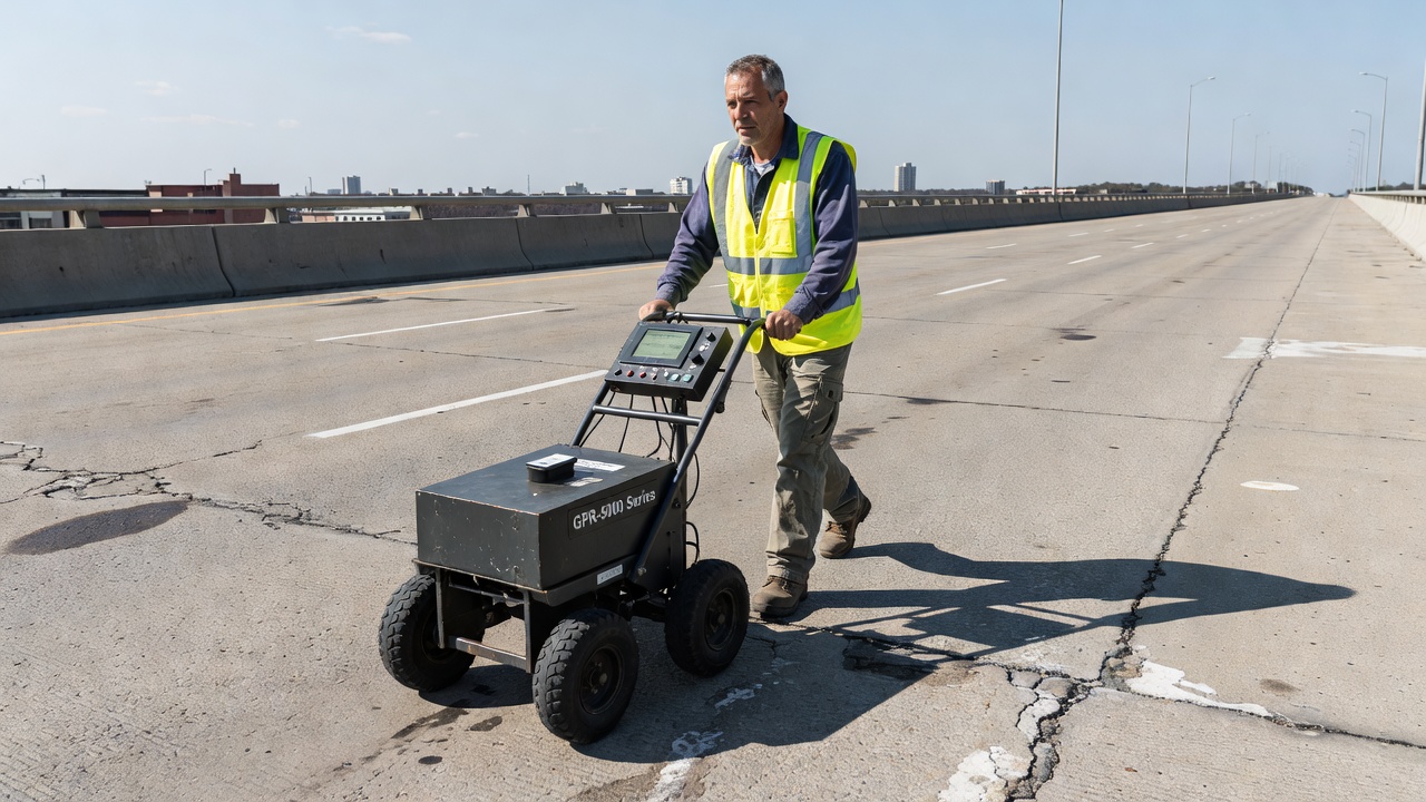
Principle: GPR transmits short pulses of electromagnetic energy (typically 400 MHz to 2.6 GHz for bridge deck inspection, lower frequencies of 100-400 MHz for deep penetration) into the structure. Reflections occur at interfaces between materials with different dielectric permittivity — concrete, reinforcement, voids, delaminations, asphalt overlays, and the bottom surface. The reflected signals are recorded as a function of two-way travel time, creating a radargram (distance vs. time cross-section).
For concrete infrastructure, GPR is used to:
Scanning configurations: GPR data can be collected using air-launched horn antennas (non-contact, vehicle-mounted for traffic-speed surveys) or ground-coupled antennas (pushed along the surface for higher resolution). Multi-channel GPR arrays (with 8-32 antenna channels) enable 3D mapping of entire bridge decks in a single pass.
Interpretation: GPR data interpretation requires significant expertise. Signal attenuation, clutter from reinforcement, and variable moisture conditions can mask defects. The SHRP 2 R06A report (Second Strategic Highway Research Program) provides comprehensive guidance on GPR data collection, processing, and interpretation for bridge deck condition assessment.
Radiographic testing uses X-rays or gamma rays to penetrate concrete and create a radiographic image on film or digital detector. The IAEA Guidebook dedicates a full chapter to RT for concrete inspection. Gamma sources (Iridium-192, Cobalt-60) can penetrate up to 600 mm of concrete; X-ray equipment up to 450 mm.
RT is primarily used for:
Limitations: RT requires access to both sides of the element (source on one side, detector on the other). Strict radiation safety protocols require exclusion zones, trained radiation safety officers, and regulatory compliance. Field radiography is slow and expensive compared to other NDT methods, limiting its use to critical applications where no alternative method provides adequate information.
Electrochemical NDT methods evaluate the corrosion condition of steel reinforcement in concrete structures. Corrosion of reinforcement is the leading cause of premature deterioration of concrete infrastructure worldwide, costing billions annually in repair and replacement. These methods provide early warning before visible damage (cracking, spalling, rust staining) appears.
Half-cell potential (HCP) measurement, standardized as ASTM C876, is the most widely used electrochemical NDT method for assessing corrosion risk of reinforcement in concrete.
Principle: A reinforcing bar actively corroding in concrete creates an electrochemical cell with anodic (corroding) and cathodic (passive) regions. The electrical potential difference between the reinforcement and a reference electrode placed on the concrete surface provides a measure of corrosion activity. The reference electrode — typically copper/copper sulfate (CSE) or silver/silver chloride (Ag/AgCl) — is connected to a high-impedance voltmeter and the reinforcement.
ASTM C876 interpretation criteria for copper/copper sulfate electrode:
Procedure: HCP measurements are taken on a grid pattern (typically 0.5 × 0.5 m or 1 × 1 m spacing) covering the entire exposed area. The concrete surface is pre-wetted to ensure good electrical contact between the reference electrode and concrete. The reinforcement must be electrically continuous and accessible for connection. Results are presented as equipotential contour maps showing zones of corrosion probability.
Limitations: HCP does not provide corrosion rate information — only the thermodynamic probability of active corrosion. Results can be influenced by concrete resistivity (high resistivity = smaller potential gradients), oxygen availability, moisture content, and the presence of epoxy-coated reinforcement. HCP cannot detect the extent of section loss in reinforcement.
Concrete resistivity is a measure of the concrete’s ability to resist the flow of electrical current, which directly influences corrosion rate. High resistivity concrete slows the flow of corrosion current between anodic and cathodic sites, reducing corrosion rates even when corrosion is thermodynamically possible.
Measurement methods:
Interpretation: Concrete resistivity values and their correlation to corrosion risk:
Resistivity is influenced by moisture content, temperature, chloride content, pore structure, and cementitious material type. Measurements should be corrected for temperature (typically to 20°C) and interpreted in context with HCP data.
Linear polarization resistance (LPR), described in ASTM G59 and ACI 222.3R, provides a quantitative measurement of instantaneous corrosion rate of reinforcement in concrete. The method applies a small potential perturbation (±10 to ±30 mV) to the reinforcement and measures the resulting current response. The polarization resistance (Rp) is inversely proportional to corrosion current density (Icorr), which can be converted to section loss rate (mm/year) using Faraday’s law.
LPR measurements require:
Typical corrosion rates: < 0.1 μm/year (passive), 0.1-0.5 μm/year (low to moderate), 0.5-1.0 μm/year (high), > 1.0 μm/year (very high). Long-term monitoring (6-24 months) provides more reliable data than single-point measurements due to environmental variability.
Infrared thermography (IRT) is a non-contact, full-field NDT method that uses thermal cameras to detect surface temperature variations caused by subsurface defects, moisture, or material property variations. IRT is standardized by ASTM E2582 for inspection of composite structures and widely applied to infrastructure assessment.
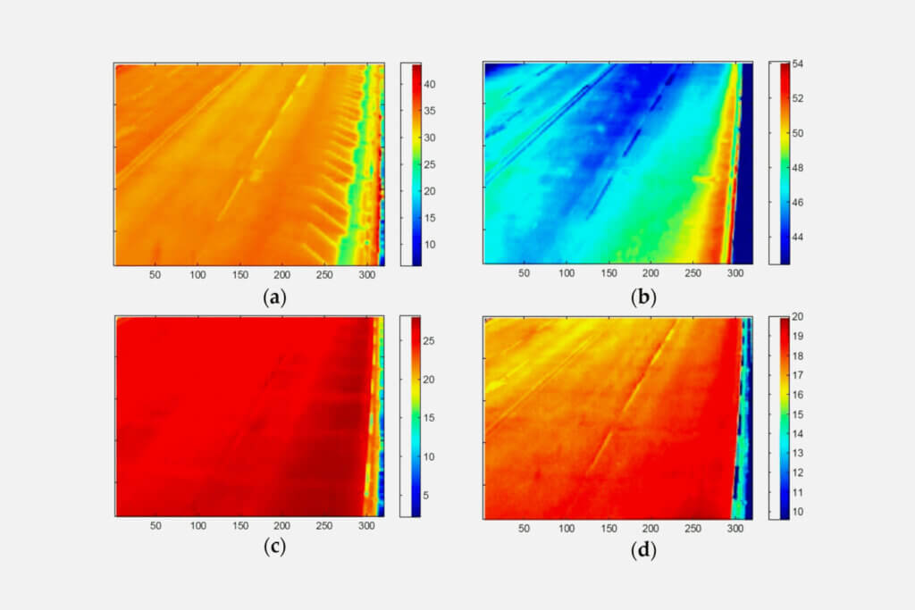
Principle: All objects emit infrared radiation proportional to their surface temperature (Stefan-Boltzmann law). Thermal cameras (microbolometer or cooled InSb detectors) capture this radiation and create temperature maps (thermograms) with sensitivity of 0.01-0.05°C. Subsurface defects — delaminations, voids, moisture accumulation — alter the thermal properties (thermal conductivity, heat capacity, density) of the material, causing localized surface temperature differences during periods of natural or imposed thermal flux.
For concrete infrastructure, two approaches are used:
Applications: IRT is used for:
Advantages: IRT is non-contact, rapid (traffic-speed data collection), and provides full-field coverage (not point-by-point). Modern drone-mounted thermal cameras enable safe inspection of elevated and hard-to-reach structures.
Limitations: IRT is surface-only (detects defects indirectly through thermal surface signatures). Detection requires adequate thermal contrast — influenced by time of day, weather conditions (cloud cover, wind, rain), surface emissivity variations, and overlay depth. Defects deeper than 150-200 mm in concrete are difficult to detect. IRT cannot characterize defect depth or provide thickness information. Results require correlation with other NDT methods (impact-echo, GPR, core verification) for definitive defect confirmation.
Effective infrastructure inspection requires matching NDT methods to specific defect types and assessment objectives. No single method detects all defect types; a multi-method approach — combining complementary techniques — is recommended by ACI 228.2R-13 and the SHRP 2 R06A program for comprehensive condition assessment.
The table below summarizes the effectiveness of major NDT methods for common infrastructure inspection objectives:
| Inspection Objective | Visual | Rebound Hammer | UPV | Impact-Echo | GPR | IRT | HCP | Radiography |
|---|---|---|---|---|---|---|---|---|
| Delamination detection | Moderate | Poor | Poor | Excellent | Good | Excellent | N/A | Good |
| Corrosion activity | Poor | N/A | N/A | N/A | Moderate | N/A | Excellent | N/A |
| Voids in concrete | Poor | N/A | Good | Excellent | Good | Moderate | N/A | Excellent |
| Honeycombing | Poor | Poor | Excellent | Moderate | Moderate | Poor | N/A | Good |
| Crack detection (surface) | Excellent | N/A | Moderate | N/A | N/A | Moderate | N/A | N/A |
| Crack detection (internal) | N/A | N/A | Excellent | Moderate | Poor | N/A | N/A | Good |
| Concrete strength estimation | N/A | Good | Good | Poor | N/A | N/A | N/A | N/A |
| Reinforcement location | N/A | N/A | Poor | N/A | Excellent | N/A | N/A | Excellent |
| Cover depth measurement | N/A | N/A | N/A | N/A | Excellent | N/A | N/A | Good |
| Tendon duct inspection | Poor | N/A | Excellent (UTT) | Good | Good | N/A | N/A | Excellent |
| ASR detection | Good | N/A | Good | Moderate | Poor | N/A | N/A | N/A |
| Freeze-thaw damage | Good | Moderate | Good | Good | Moderate | Good | N/A | N/A |
| Pavement thickness | N/A | N/A | N/A | Excellent | Excellent | N/A | N/A | N/A |
| Moisture mapping | Moderate | N/A | N/A | N/A | Excellent | Excellent | N/A | N/A |
Key selection principles:
For corrosion assessment — Start with half-cell potential mapping (ASTM C876) to identify zones of active corrosion probability. Follow with concrete resistivity measurements to assess corrosion rate potential. GPR can identify chloride-contaminated areas through dielectric property changes. Confirm with selective chloride sampling and carbonation depth testing.
For delamination detection — Impact-echo provides the most reliable point-by-point detection. IRT enables rapid full-field screening. GPR can detect moisture-filled delaminations. Chain dragging (sounding) is the simplest method but limited by traffic noise and depth of detection.
For internal void and honeycomb detection — Ultrasonic tomography provides the most detailed volumetric imaging. Impact-echo can detect planar voids. Radiography is effective but logistically demanding. UPV can indicate zones of reduced quality for targeted investigation.
For reinforcement evaluation — GPR maps bar location, cover depth, and spacing most efficiently. Radiography confirms bar size and condition. Half-cell and LPR assess corrosion condition. Cover meters (electromagnetic) provide localized cover measurements.
For thickness measurement — Impact-echo (ASTM C1383) and GPR (ASTM D4748) both provide accurate thickness measurements of concrete slabs and pavement layers. GPR is faster for large areas; impact-echo is more accurate for single-point measurements.
The IAEA-recommended survey protocol for concrete structures follows a three-tiered approach:
Tier 1 (Reconnaissance): Visual inspection, condition survey, document review. Identifies obvious defects and selects areas for detailed investigation.
Tier 2 (Screening): Rapid NDT methods applied over large areas — GPR and IRT for bridge decks, UPV for member screening, rebound hammer for uniformity assessment. Prioritizes areas requiring detailed investigation.
Tier 3 (Detailed Investigation): Focused application of high-resolution methods — impact-echo for delamination mapping, ultrasonic tomography for volumetric defect imaging, half-cell and LPR for corrosion assessment, selective coring for calibration. Provides quantitative data for condition assessment, load rating, and repair design.
The integration of drone-based visual inspection with traditional NDT methods represents a significant advancement in infrastructure condition assessment. Drones provide safe, rapid, and cost-effective access to structures that are difficult, dangerous, or expensive to inspect using conventional means — bridges, towers, chimneys, dams, tunnels, and elevated structures.

Drone capabilities for infrastructure inspection include:
Complementarity with ground-based NDT:
Drones are most effective for tier 1 screening of large structures, rapidly identifying surface condition anomalies that warrant closer investigation. This creates an efficient workflow:
This integrated approach reduces overall inspection time by 40-60% compared to traditional methods (lane closure, scaffolding, underbridge trucks) while providing more comprehensive data coverage. For the pilot, it eliminates dangerous operations — working in live traffic lanes, on elevated platforms, or at height without fall protection.
Current limitations of drone-based inspection include:
Despite these limitations, the trend is clear: drone-first inspection protocols followed by targeted in-situ NDT are becoming standard practice for infrastructure owners seeking to maximize coverage, minimize cost, and improve inspector safety.
NDT of infrastructure is governed by a comprehensive framework of international, national, and industry standards that define equipment requirements, test procedures, personnel qualification, data interpretation, and reporting formats. Compliance with applicable standards is essential for ensuring repeatability, comparability, and legal defensibility of NDT results.
ASTM publishes the most widely referenced NDT standards for infrastructure in North America and globally:
| Standard | Title | Application |
|---|---|---|
| ASTM C42 | Standard Test Method for Obtaining and Testing Drilled Cores and Sawed Beams of Concrete | Core extraction and compressive/flexural testing (destructive, used for NDT calibration) |
| ASTM C597 | Standard Test Method for Ultrasonic Pulse Velocity Through Concrete | UPV measurement for concrete uniformity and quality |
| ASTM C805 | Standard Test Method for Rebound Number of Hardened Concrete | Rebound hammer testing |
| ASTM C876 | Standard Test Method for Corrosion Potentials of Uncoated Reinforcing Steel in Concrete | Half-cell potential mapping |
| ASTM C1383 | Standard Test Method for Measuring the P-Wave Speed and the Thickness of Concrete Plates Using the Impact-Echo Method | Impact-echo thickness measurement and wave speed |
| ASTM C1760 | Standard Test Method for Bulk Electrical Conductivity of Hardened Concrete | Concrete resistivity measurement |
| ASTM D4748 | Standard Test Method for Determining the Thickness of Bound Pavement Layers Using Short-Pulse Radar | GPR thickness measurement |
| ASTM D6432 | Standard Guide for Using the Surface Ground Penetrating Radar Method for Subsurface Investigation | GPR data collection and interpretation |
| ASTM E2582 | Standard Practice for Infrared Flash Thermography of Composite Panels and Repair Patches Used in Aerospace Applications | IR thermography (adapted for infrastructure) |
| ASTM E165 | Standard Practice for Liquid Penetrant Testing for General Industry | Dye penetrant testing of metallic components |
| ASTM E1444 | Standard Practice for Magnetic Particle Testing | MT of ferromagnetic materials |
| ASTM G59 | Standard Test Method for Conducting Potentiodynamic Polarization Resistance Measurements | LPR corrosion rate measurement |
ACI Committee 228 documents are the primary guidance documents for NDT of concrete:
AASHTO standards govern bridge and highway infrastructure inspection in the United States:
NDT personnel qualification is governed by ISO 9712, ASNT SNT-TC-1A (American Society for Nondestructive Testing), or national certification schemes. Personnel are certified at three levels:
For infrastructure NDT, the ACI Concrete NDT Technician Certification Program provides specialized qualification for concrete testing. Many transportation agencies require NDT reports to be prepared or reviewed by a Professional Engineer (PE) with demonstrated NDT experience.
Selecting the appropriate standard for a given inspection project requires consideration of the contractual requirements, geographic jurisdiction, asset type, and regulatory framework. The most robust approach combines the procedural rigor of ASTM/AASHTO methods with the interpretive guidance of ACI committee reports and the personnel qualification requirements of ISO 9712 or equivalent schemes.
The IAEA Guidebook provides a complete NDT methodology framework — from inspection planning through data interpretation and reporting — that is applicable to concrete infrastructure worldwide. When used in conjunction with project-specific standards and quality assurance plans, NDT provides reliable, defensible data for informed infrastructure management decisions.
Leverage the full NDT toolbox combined with advanced drone-based visual inspection to assess infrastructure condition faster, safer, and more comprehensively. Our solutions integrate multiple NDT methods for actionable asset intelligence.
Impact-Echo is a stress-wave nondestructive testing method where a short-duration mechanical impact on a concrete surface generates stress waves that reflect fr...
Ultrasonic Testing (UT) uses high-frequency sound waves (typically 20 kHz–200 MHz) to detect internal flaws, measure thickness, and assess material properties i...
Infrared Thermography (IRT) is a non-contact, non-destructive testing method that detects surface temperature variations caused by subsurface defects such as de...