Nuclear Density Gauge for Soil and Asphalt Density
The nuclear density gauge is a field instrument that uses gamma radiation and neutron thermalization to measure in-place density and moisture content of soil, aggregate, and asphalt. Covers principles (direct transmission vs backscatter), calibration, safety regulations, and comparison with non-nuclear alternatives.
Nuclear Density Gauge — Principle of Operation
The nuclear density gauge (NDG) — also referred to as a Troxler gauge, nuclear compaction gauge, or nuclear moisture-density gauge — is a portable field instrument that uses ionizing radiation to measure the in-place density and moisture content of construction materials. It is the most widely used quality control tool for verifying compaction of soil, aggregate base, and asphalt pavement layers on highway, airfield, dam, and general civil engineering projects worldwide.
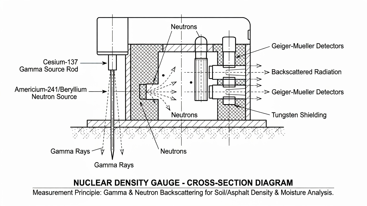
The instrument operates on two distinct physical principles. Density measurement relies on gamma ray attenuation using a sealed source of Cesium-137 (Cs-137) — a radioactive isotope that emits gamma photons at 0.662 MeV. This source is housed in a retractable rod assembly at the tip of a tungsten-shielded probe. When the rod is extended into the test material, gamma radiation passes through the material along a fixed path length to Geiger-Mueller (GM) tubes or scintillation detectors located in the gauge base. The governing physics is described by Beer’s Law of exponential attenuation: I = I₀ × B × e^(−μρx), where I is the detected count rate, I₀ is the reference count rate, B is a build-up factor accounting for scattered photons, μ is the mass attenuation coefficient (material-dependent, in cm²/g), ρ is the material density (g/cm³), and x is the fixed path length. The count rate decreases as density increases because denser materials contain more electrons per unit volume that interact with and attenuate the incident gamma photons. The gauge’s internal microprocessor uses a factory-calibrated correlation curve stored in firmware to convert the measured count rate into a wet density reading in pounds per cubic foot (pcf) or kilograms per cubic meter (kg/m³).
Moisture content measurement uses the neutron thermalization (moderation) principle with a separate sealed source of Americium-241/Beryllium (Am-241/Be) permanently mounted in the gauge base. The Am-241 emits alpha particles that strike beryllium nuclei, producing fast (high-energy) neutrons via the nuclear reaction ⁹Be(α,n)¹²C. These fast neutrons are emitted isotropically into the surrounding material, where they collide with atomic nuclei. Hydrogen atoms are the most effective neutron moderators because a neutron and a proton have nearly equal mass — a neutron can lose up to 100% of its kinetic energy in a single head-on collision with a hydrogen nucleus. Collisions with heavier elements such as oxygen, silicon, aluminum, and calcium transfer much less energy per collision. The fast neutrons that are thermalized (slowed to approximately 0.025 eV, corresponding to thermal equilibrium at room temperature) within the material diffuse back toward the gauge, where a detector — typically a helium-3 (³He) or boron trifluoride (BF₃) proportional tube — counts these thermalized neutrons. The higher the thermal neutron count, the more hydrogen present in the material. Since water (H₂O) contains two hydrogen atoms per molecule, the gauge can calculate moisture content in pcf or kg/m³.
The Cesium-137 source has a half-life of 30.17 years, requiring decay correction in the calibration algorithms. Typical activity in portable gauges ranges from 8 to 40 millicuries (mCi). The source material is fused into a ceramic pellet approximately the size of a small pebble, then double-encapsulated in laser-welded stainless steel capsules — creating a virtually impenetrable sealed source assembly. The Americium-241/Beryllium source has a half-life of 432.2 years, so decay correction is negligible over the operational life of the gauge. Typical activity is approximately 40 mCi, emitting approximately 10⁴ neutrons per second per mCi. The Am-241/Be source is encased in the gauge base and is never extended into the material — it remains permanently in the shielded position within the gauge housing.
In the retracted (safe, transport) position, both sources are shielded by the gauge construction. The Cs-137 source rod retracts into a tungsten sliding block — tungsten is chosen for its high density of 19.3 g/cm³, providing superior radiation shielding compared to lead (11.3 g/cm³). The Am-241/Be source is permanently shielded within the gauge housing by a combination of tungsten and hydrogenous materials. Surface dose rates at the gauge exterior in the shielded position are typically less than 0.5 mrem/hr (5 μSv/hr), well below regulatory limits for controlled access areas.
Direct Transmission vs Backscatter Mode
The nuclear density gauge operates in two fundamentally different measurement modes, each with distinct physics, procedures, and applications.
Direct transmission mode is the primary method for soil, aggregate base, and subgrade compaction testing per ASTM D6938 and AASHTO T310. The procedure begins with driving a guide pin into the compacted material to create a pilot hole at the desired test depth. The gauge is positioned over the hole, and the source rod is lowered into the hole to the selected depth — typically 2, 4, 6, 8, 10, or 12 inches (50 to 300 mm). The selected depth should match the compacted lift thickness or the layer under evaluation. Gamma radiation travels from the source at the rod tip, through the material along a cone-shaped path, to the GM tubes located in the gauge base at the opposite end of the gauge from the source rod. In this configuration, the count rate follows the direct exponential attenuation relationship: I = I₀ × B × e^(−μρd), where d is the fixed source-to-detector distance. The measurement volume is relatively large and representative, encompassing a roughly conical volume of material between the source and detectors. The accuracy of direct transmission is typically ±1 pcf (±16 kg/m³) or better for most soils. Direct transmission is the preferred mode for acceptance testing because it measures bulk density of a larger, more representative material volume, is less sensitive to surface irregularities and roughness, provides density data at a specific depth horizon, and is more accurate for deeper lifts. The primary limitation is that it requires a pilot hole, making it minimally destructive to the surface, and it cannot be used on pavement surfaces such as asphalt or concrete.
Backscatter mode is the standard method for asphalt pavement density testing per ASTM D2950 and AASHTO T355. The source rod is lowered only until it is flush with the bottom of the gauge housing — not extended into the material. In this configuration, the source and detectors are in the same horizontal plane within the gauge. Internal tungsten shielding between the source and detectors prevents direct radiation from reaching the detectors. Radiation must exit the gauge, enter the test material, undergo Compton scattering off electrons in the material, and return to the detectors. The physics is fundamentally different from direct transmission — more detected radiation corresponds to higher density because more scattering centers (electrons) exist to redirect photons back to the detector. The measurement is heavily weighted to the top 2 to 4 inches (50 to 100 mm) of material, with approximately 50% of the signal coming from the top 1 inch (25 mm). Backscatter mode is completely non-destructive — no hole is required — making it ideal for testing finished asphalt pavements, thin overlays, and surfaces where damage cannot be tolerated. The accuracy is typically ±1.5 to 2 pcf (±24 to 32 kg/m³), and the measurement is more sensitive to surface conditions such as texture, roughness, debris, and moisture.
Parameter
Direct Transmission
Backscatter
Source position
Extended into material at specified depth
Flush with gauge base
Measurement volume
Large, cone-shaped path
Small, surface-weighted
Depth of measurement
Specified depth (2–12 in / 50–300 mm)
Top 2–4 in (50–100 mm), gradient
Destructive to surface
Requires pilot hole
Non-destructive
Primary application
Soils, granular base, subgrade
Asphalt pavements, thin lifts
Typical accuracy
±1 pcf (±16 kg/m³) or better
±1.5–2 pcf (±24–32 kg/m³)
Governing standard
ASTM D6938 / AASHTO T310
ASTM D2950 / AASHTO T355
The choice between modes is driven by the material type, lift thickness, and acceptance testing protocol. For deep lifts of soil or aggregate base, direct transmission is mandatory. For thin asphalt overlays less than 1.5 to 2 inches (38 to 50 mm) thick, even backscatter readings may be influenced by the underlying layer, requiring careful interpretation or alternative test methods such as core extraction.
Measurement of Density and Moisture Content
The nuclear density gauge measures wet density and moisture content simultaneously during a single 15 to 60 second test. The test duration is selected by the operator — longer test durations increase precision by accumulating more radiation counts, reducing statistical counting error, while shorter durations allow higher testing productivity.
The wet density (γ_wet) is determined from the gamma attenuation count rate using the factory-calibrated correlation. The moisture content (ω) is determined from the thermal neutron count rate. The gauge then computes dry density using the fundamental soil mechanics relationship:
γ_dry = γ_wet / (1 + ω/100)
Where γ_dry is the dry density, γ_wet is the bulk wet density, and ω is the moisture content expressed as a percentage of the dry weight of the material.
Once dry density is obtained, percent compaction is calculated relative to a laboratory reference value:
For soil compaction, γ_dry_max_proctor is the maximum dry density from the laboratory Proctor test — either Standard Proctor (ASTM D698) or Modified Proctor (ASTM D1557) , depending on the project specification. For airport pavements serving aircraft weighing 60,000 lbs (27,200 kg) or more, the FAA AC 150/5320-6G requires the Modified Proctor (ASTM D1557) compaction effort.
For asphalt compaction, the calculation differs:
% Compaction = (γ_field / γ_lab_target) × 100
Where γ_lab_target is typically one of three reference values: Theoretical Maximum Density (TMD) from the Rice method (ASTM D2041), Marshall specimen density (ASTM D1559), or Control strip density — a test section compacted to refusal that establishes the achievable density for the specific mix and rolling pattern.
The gauge incorporates a proctor correction or moisture offset feature that is critical for accurate dry density determination. The neutron method measures total hydrogen in the material, including hydrogen in chemically bound water within clay mineral structures and hydrogen in organic matter — not just free water that would be removed by oven drying at 110°C in the laboratory. The moisture offset is determined by comparing gauge moisture readings to oven-dry moisture content from samples taken at the same test locations. This offset is entered into the gauge as a correction factor specific to the material being tested and must be re-established for different soil types encountered on a project.
The percent compaction value is the final acceptance criterion for most compaction specifications. Typical specifications for soil compaction require 90% to 95% of maximum dry density (Standard or Modified Proctor), depending on the layer type and its position in the pavement structure. Subgrade typically requires 90% to 93%, base course requires 95% to 98%, and asphalt surface requires 92% to 97% of TMD.
Calibration — Standard Count, Moisture Offset, and Frequency
Calibration of the nuclear density gauge is a multi-level process that ensures measurement accuracy and traceability to national standards. The calibration system involves three distinct levels: factory calibration, daily field verification (standard count), and annual recalibration.
Factory calibration is performed by the gauge manufacturer before delivery and establishes the fundamental count-rate-to-density and count-rate-to-moisture conversion curves. The manufacturer uses reference blocks of known density and composition — typically a magnesium block at approximately 100 pcf (1,600 kg/m³), an aluminum block at approximately 170 pcf (2,720 kg/m³), and granite or limestone blocks covering the extended density range. The gauge is tested on each block at multiple source rod depths (for direct transmission) and in backscatter mode, generating calibration curves that are stored in the gauge’s firmware. The factory calibration is traceable to NIST (National Institute of Standards and Technology) reference standards through an unbroken chain of comparisons.
Daily standard count is the most critical field calibration procedure and must be performed before each day of gauge use. The procedure follows the APNGA (American Portable Nuclear Gauge Association) guidance:
The gauge base and standard block top surface are cleaned of dirt, moisture, and debris.
The standard block is placed on stable material with a density of at least 100 pcf — never on a truck tailgate or unstable surface.
The gauge is placed on the standard block with the butt plate firmly against the block guide.
The source rod is verified to be in the SAFE (fully retracted) position.
No other nuclear gauges are within 30 feet (9 meters).
No large vertical objects such as walls, vehicles, or personnel are nearby.
The gauge has warmed up for approximately 10 minutes before taking the standard count.
A 1-minute or 4-minute count is taken, as specified by the agency quality control plan.
Acceptance criteria for the standard count are: the density count must be within ±1% of the established reference (baseline) count, and the moisture count must be within ±2% of the established reference count. If the standard count falls outside these limits, the operator must troubleshoot before proceeding. Possible causes include contamination on the block or gauge base, gauge electronics malfunction, or excessive temperature differential between the gauge and the environment. If the standard count has not been taken for more than 60 days, a new baseline must be established by averaging three to four consecutive standard counts. If the standard count repeatedly fails, the gauge must be returned to the manufacturer for service and recalibration.
Annual calibration is required at a minimum of once per calendar year and must be performed by an authorized technician holding appropriate qualifications under the radioactive materials license. The annual calibration includes: reference block verification against NIST-traceable standards, source geometry checks to ensure the source rod and detectors are properly aligned, count rate stability evaluation across the full operating temperature range, electronics verification including the microprocessor, display, and data storage systems, and update of the decay correction factor for the Cs-137 source. Calibration documentation must show traceability to NIST reference standards, the radiation safety records consistent with the radioactive materials license, the calibration status tied to field data validity — proof that the gauge was in-calibration at the time each field test was performed, and the calibration intervals and gap tracking documenting any triggering events between calibrations.
Five triggering events require recalibration regardless of the annual cycle: transport damage or impact — shock from truck beds or drops, source repair or replacement, electronics service — repairs to detectors, counters, or displays, reference block damage or replacement, and unusual count rate behavior in the field compared to historical data.
The moisture offset is established for each project and each distinct soil type encountered. The procedure involves: compacting a test section of the material, taking gauge moisture readings at multiple locations, collecting soil samples from the same locations, determining moisture content by standard oven drying (ASTM D2216), and computing the offset as the difference between gauge moisture and oven-dry moisture. This offset is entered into the gauge for the specific material and remains valid as long as the material type does not change.
Temperature effects on gauge operation are significant. Gauges contain temperature-sensitive electronics and detectors. Extreme heat — such as asphalt surface temperatures exceeding 150°F (65°C) — or extreme cold can affect count rates and electronic stability. Standard counts should be taken at the test site under temperature conditions similar to those during testing. Gauges should be allowed to temperature-stabilize before use, following the manufacturer-recommended warm-up time. Cold weather affects battery performance and LCD display response, while hot asphalt surfaces can cause the gauge base to expand, altering the source-to-detector geometry.
Operation and Radiation Safety
Operation of a nuclear density gauge is governed by a comprehensive regulatory framework designed to protect operators, the public, and the environment from radiation exposure. The regulatory structure in the United States involves three separate federal regulations covering different aspects of gauge use, plus parallel state regulations in Agreement States.
Radiation safety training is the foundation of safe gauge operation. Initial training requires a minimum of 8 hours of classroom instruction on radiation safety principles, with many programs requiring 16 to 40 hours. The training curriculum, as specified in NRC NUREG 1556, Volume 1 (Program-Specific Guidance About Portable Gauge Licenses), covers: atomic theory and radiation fundamentals, radiation safety principles including time, distance, and shielding, dose calculations and ALARA (As Low As Reasonably Achievable) philosophy, gauge operation procedures for both direct transmission and backscatter modes, field applications including test site selection and surface preparation, transportation requirements under DOT HAZMAT regulations, accident and emergency procedures including source damage or loss scenarios, routine maintenance and leak testing procedures, and regulatory requirements including license conditions and inspection protocols. Operators must pass a written exam with a minimum score of 80% to receive certification. Training certificates are issued and maintained on file. Annual refresher training updates operators on regulatory changes, procedural updates, and safety reminders. HAZMAT refresher training under 49 CFR 172.704 is required every 3 years, covering the safe transport of portable nuclear gauges under DOT regulations.
The Radiation Safety Officer (RSO) is the designated individual responsible for managing the radiation protection program. Per APNGA and NRC guidance, the RSO responsibilities include: ALARA program management — emphasizing the As Low As Reasonably Achievable philosophy to all workers, reviewing and updating procedures to minimize exposures, dosimetry review — reviewing dosimetry reports at least quarterly, investigating any excessive doses within 30 days, and documenting corrective actions, personnel notifications — providing annual written radiation exposure notifications to all monitored personnel, periodic internal inspections — observing workers during gauge transport and field operations to verify compliance with procedures, license compliance — ensuring license conditions remain current and filing amendments for address changes, new ownership, or RSO changes, and SSD certificate maintenance — ensuring Sealed Source and Device certificates are on file for each gauge model.
Transport regulations under DOT 49 CFR Parts 100–185 classify nuclear gauges as Class 7 Radioactive Materials. The transport requirements include: proper shipping papers with the proper shipping name “Radioactive material, Type A package, limited quantity,” markings including the UN identification number (UN2910 for Type A packages), labels including the Radioactive White-I or Yellow-II label depending on the transport index, and placards on vehicles when required by the total activity. Gauges in exclusive-use vehicles have relaxed labeling requirements when the surface dose rate is below specified limits. The gauge package must meet DOT 7A Type A specification — a packaging standard that ensures the source remains contained under normal transport conditions including vibration, impact, and temperature extremes. The gauge must be secured in the vehicle to prevent sliding, tipping, or falling during transport. The Transport Index (TI) — the maximum dose rate at 1 meter from the package surface in mrem/hr — must be determined and declared on shipping documents. Gauge transport personnel must hold current HAZMAT training certification.
Licensing requirements are administered by the Nuclear Regulatory Commission (NRC) in non-Agreement States and by equivalent state regulatory agencies in the 39 Agreement States. The regulations are defined in 10 CFR Parts 30 through 36. A specific Radioactive Materials License is required for gauge ownership and operation. The license specifies: the authorized gauge models and serial numbers, the maximum source quantities for both Cs-137 and Am-241/Be, the authorized users who are permitted to operate the gauges, the approved storage locations, the designated RSO, and the expiration date. The license application requires a description of the radiation safety program, RSO qualifications documentation, facility diagrams showing storage areas, operating and emergency procedures, and a leak test program description. Reciprocity provisions allow licensees to work temporarily in other states under reciprocal recognition agreements.
Leak testing is required every 6 months for each sealed source. A wipe test is performed on the source rod tip and exterior surfaces, and the wipe is analyzed for removable radioactive contamination. The acceptable limit is less than 0.005 microcuries (185 Bq) of removable contamination per source according to NRC regulations. Leak test records must be maintained for 3 years after the test date. If a leak is detected exceeding 0.005 µCi, immediate corrective action is required including source removal from service and reporting to the regulatory agency.
Storage requirements per NRC and APNGA guidance include: gauges must be stored in a locked, secured area when not in use, access limited to authorized, trained personnel, the storage area must be posted with “Caution — Radioactive Material” signs with the standard radiation trefoil symbol, annual radiation surveys of storage areas are required and documented, controlled access with lock and key or electronic access system, separation from personnel work areas by distance or shielding, the gauge source rod must be in the fully shielded (locked) position when stored, and the storage area must be fire-resistant and secure against theft.
Personnel monitoring requires TLD (thermoluminescent dosimeter) or OSL (optically stimulated luminescence) dosimeters for all gauge operators. Film badges are not suitable for neutron measurement because they do not efficiently detect thermal neutrons — TLDs are preferred because they measure both gamma and neutron radiation. Dosimeters are typically exchanged quarterly or monthly, and the dosimetry service provider analyzes the dosimeters and reports the dose equivalent. The annual occupational dose limit is 5 rem (50 mSv) total effective dose equivalent, with ALARA investigation levels typically set much lower at 125 mrem per quarter (1.25 mSv). Annual dose reports must be provided to each monitored individual.
Nuclear Gauge in Asphalt Compaction — ASTM D2950
Asphalt pavement density testing using the nuclear gauge is governed by ASTM D2950/D2950M-22 — Standard Test Method for Density of Bituminous Concrete in Place by Nuclear Methods, and the equivalent AASHTO T355. This standard is specifically applicable to hot mix asphalt (HMA) pavements and uses the backscatter mode exclusively — the source rod remains flush with the gauge base, making the test completely non-destructive.
The testing procedure begins with surface preparation — the test area must be swept clean of loose aggregate, dirt, and debris. The gauge must be in firm contact with the pavement surface. A thin layer of fine sand or a seating compound may be used to ensure full contact if the surface is rough or textured, but the influence of such materials on the density reading must be evaluated during correlation. The gauge must be allowed to warm up and reach thermal equilibrium with the pavement temperature — this is particularly critical on hot asphalt surfaces where the pavement temperature can exceed 150°F (65°C) and the gauge base temperature can drift significantly during a testing session.
The density target is selected from one of three reference values depending on the project specification. Theoretical Maximum Density (TMD) per ASTM D2041 (Rice method) represents the voidless density of the mixture — the density the pavement would have if all air voids were eliminated. The percent of TMD is the most fundamental reporting method because it directly relates to air voids: 93% of TMD corresponds to 7% air voids, 96% of TMD corresponds to 4% air voids. Marshall specimen density per ASTM D1559 is the density of laboratory-compacted specimens at the design number of blows (typically 75 blows per face for airport pavements). Control strip density is established by compacting a test section of the pavement to refusal — the roller operator continues rolling until no further density gain is measured by the nuclear gauge, and the average density of the control strip at that point becomes the target for the project.
Typical specifications require the average of five nuclear gauge readings to exceed 92% of TMD (corresponding to a maximum of 8% air voids), or 95% to 97% of Marshall density, or 98%+ of control strip density. The FAA specification for airport HMA pavements (Item P-401 in AC 150/5370-10H) requires in-place density of 96% of laboratory density, which corresponds to approximately 92% to 93% of TMD and in-place air voids of 7% to 8%.
Nuclear gauge testing during asphalt placement provides real-time feedback to the roller operator. Testing is performed between roller passes to monitor density gain, identify when optimum density is achieved before over-rolling begins, and detect under-compacted areas that require additional rolling passes. This real-time capability is one of the most important advantages of nuclear gauges over core testing — a core requires 24 to 48 hours from extraction to density determination, by which time the paving operation has moved far from the test location.
A critical consideration in ASTM D2950 is that backscatter readings are influenced by the density of underlying layers. For thin lifts less than 1.5 to 2 inches (38 to 50 mm) thick, the measured density may not represent the overlay alone — a significant portion of the signal comes from the existing pavement layer below. This limitation requires careful interpretation of backscatter data on thin overlays and, in some cases, the use of alternative methods such as core extraction for acceptance.
The TRB Circular 321 (Transportation Research Board, June 1987) surveyed 49 state highway agencies on their use of nuclear density gauges for asphalt compaction. The survey found that 39 of 48 agencies used end-result specifications for full-depth asphalt, 31 relied primarily on nuclear gauges versus cores for acceptance, the mean sampling frequency for nuclear gauge users was 1 test per 1,250 lane-feet (380 lane-meters), and for core users the frequency was 1 test per 3,283 lane-feet (1,000 lane-meters). Nearly all agencies shifted from end-result to method-type specifications for thin lifts at thicknesses below 1 to 2 inches.
Nuclear Gauge in Soil Compaction — ASTM D6938
Soil and aggregate base compaction testing with the nuclear gauge is governed by ASTM D6938-23 — Standard Test Methods for In-Place Density and Water Content of Soil and Soil-Aggregate by Nuclear Methods (Shallow Depth), and the equivalent AASHTO T310. These standards specify direct transmission mode as the primary test method for soils.
The field procedure begins with site preparation — the test area is leveled and loose surface material is removed to ensure uniform contact between the gauge base and the soil surface. A guide pin is driven to the required test depth, then carefully removed to avoid disturbing the hole walls. The gauge is positioned over the hole with the source rod aligned to enter the hole freely. The source rod is lowered to the selected depth — typically matching the compacted lift thickness. The operator inputs the test duration (typically 30 to 60 seconds), the Proctor reference values (maximum dry density and optimum moisture content), and the moisture offset for the specific material being tested. The gauge simultaneously measures wet density and moisture content over the test duration, then computes dry density and percent compaction.
The nuclear gauge offers significant advantages over the traditional sand cone test (ASTM D1556) for soil compaction control:
Feature
Nuclear Gauge (D6938)
Sand Cone (D1556)
Test duration
15–60 seconds
20–30 minutes
Destructive to surface
Small pin hole (6–8 mm diameter)
Excavation hole required (~150 mm diameter)
Moisture measurement
Simultaneous via neutron thermalization
Separate sample required + oven drying (24 hours)
Typical repeatability
±1 pcf (±16 kg/m³)
±1–2 pcf (±16–32 kg/m³)
Test depth range
Up to 12 inches (300 mm)
Up to 12 inches (300 mm)
Equipment cost
~$8,000–$15,000
~$300–$500
Hazards
Radioactive material, regulatory requirements
None
Training required
Radiation safety + NRC license + annual refresher
Standard technician training
The nuclear gauge advantage is the ability to obtain immediate, real-time results that allow compaction effort to be adjusted on the spot. If a test location shows density below specification, additional roller passes can be applied immediately and the results verified in seconds. With the sand cone test, the 20 to 30 minute test duration means the compaction operation has moved far from the test location before results are available, and remediation requires returning to the area — a much less efficient process.
Moisture measurement issues specific to soils must be understood and addressed. The neutron method measures total hydrogen, not water specifically. This means: organic soils yield falsely high moisture readings because of hydrogen in organic matter, clay minerals with chemically bound water in their crystal structure contribute to the moisture signal, and the moisture offset must be established for each distinct soil type encountered on a project. The offset is determined by comparing gauge moisture readings to oven-dry moisture content from samples collected at the same test locations, following ASTM D2216 (Standard Test Method for Laboratory Determination of Water Content of Soil and Rock).
Nuclear gauge testing for airport pavement compaction follows FAA standards. The FAA AC 150/5320-6G (Airport Pavement Design and Evaluation, June 2021) specifies Modified Proctor compaction (ASTM D1557) for pavements serving aircraft weighing 60,000 lbs or more. The nuclear gauge is referenced as part of the nondestructive testing suite for compaction verification. Research published in 2021 on “Field Evaluations of Nuclear and Non-Nuclear Gauges as Alternates to Destructive Coring for Airport Asphalt Density Testing” confirmed that nuclear gauges can serve as practical alternatives to coring for airport pavement acceptance testing.
Non-Nuclear Alternatives — EDG, Impedance, and Dielectric Methods
The regulatory burden, safety concerns, and transport restrictions associated with radioactive materials have driven significant research and development into non-nuclear density gauges (NNDGs) . These instruments use various physical principles to infer density without using ionizing radiation.
The Electrical Density Gauge (EDG) operates on the principle of electrical impedance measurement. The gauge emits an electrical signal into the soil through contact plates on the gauge base and measures the material’s impedance — its resistance to alternating current at a range of frequencies. The impedance is related to the material’s density through a calibration curve established for the specific material type being tested. Some EDG models also measure moisture content through the dielectric response of the material. The principal advantages of the EDG are complete elimination of radioactive materials — no NRC license, radiation safety program, transport restrictions, HAZMAT requirements, or leak testing, lower training requirements because no radiation safety training is needed, no security concerns or storage restrictions, and no TLD badges or personnel dosimetry.
The Pavement Quality Indicator (PQI) — manufactured by TransTech Systems — and the PaveTracker — manufactured by Troxler Electronic Laboratories — are impedance-based devices used specifically for asphalt density testing. These instruments generate an electromagnetic field and measure how the pavement material affects the field’s characteristics. The measured response is correlated to density through a calibration relationship established for each specific asphalt mixture. The PQI and PaveTracker are handheld devices providing instantaneous readings in 2 to 5 seconds, considerably faster than the 15 to 60 second nuclear gauge test.
Dielectric measurement methods use the principle that the dielectric constant of HMA varies with density. As pavement density increases, the volume of air (dielectric constant approximately 1.0) decreases relative to the volume of aggregate (dielectric constant 5 to 7) and binder (dielectric constant 2.5 to 3.0). The measured bulk dielectric constant of the pavement mixture is therefore a function of density. This principle can be implemented through contact impedance devices or through Ground Penetrating Radar (GPR) — air-coupled GPR antennas can profile the dielectric constant of the pavement continuously at traffic speed, providing a continuous density profile rather than discrete point measurements.
A comprehensive study by Washington State University and the Idaho Transportation Department (WSU/ITD RP 210, 2015) evaluated non-nuclear density gauges as potential replacements for nuclear gauges. The key findings were:
For hot mix asphalt (HMA): After project-specific calibration, NNDGs performed comparably to nuclear gauges. Calibration factors varied between projects — no universal correction was found. Surface moisture significantly affected readings — standing water or wet pavement caused large errors. Surface fines and paint markings also affected readings. The study recommended modified test protocols for NNDGs on HMA.
For unbound materials (soils, base, subgrade): The WSU/ITD study concluded that NNDGs “are not consistently accurate or precise enough to replace NDGs” for acceptance testing on unbound materials. The measurements were particularly unreliable on granular materials and when surface moisture was present. This finding is consistent with the experience of most state DOTs — nuclear gauges remain the standard for soil compaction acceptance testing.
Method
Device Example
Principle
Application
Status
Electrical impedance
EDG
Soil dielectric response
Soil density and moisture
Limited acceptance
Electromagnetic impedance
PQI 301/380, PaveTracker
HMA dielectric response
Asphalt density
Calibrated use only
Seismic/stiffness
GeoGauge, PSPA
Mechanical wave velocity
Stiffness measurement
Not density
GPR dielectric profiling
Air-coupled GPR
Continuous dielectric profiling
Density profiling
Emerging
Intelligent Compaction
IC roller systems
Roller response + GPS
Continuous compaction
Growth area
The 10-year lifecycle cost comparison from the WSU/ITD study shows that NNDG costs are approximately $12,000 to $19,000 for HMA applications and $7,500 to $23,000 for unbound applications, compared to $15,500 to $18,000 for nuclear gauges. The costs are comparable over the equipment lifecycle, with nuclear gauge costs dominated by regulatory compliance (licensing, leak testing, dosimetry) and NNDG costs dominated by more frequent replacement and calibration requirements.
The FHWA position on non-nuclear gauges is that they can be useful quality control tools but are not yet accepted as replacements for nuclear gauges for acceptance testing of unbound materials. The AASHTO has not adopted a standard test method for non-nuclear gauges equivalent to ASTM D6938 or ASTM D2950 for nuclear gauges.
Standards — ASTM, AASHTO, FAA, and ICAO
The nuclear density gauge is governed by a comprehensive set of international and national standards that specify test methods, equipment requirements, calibration procedures, and acceptance criteria.
ASTM D6938-23 — Standard Test Methods for In-Place Density and Water Content of Soil and Soil-Aggregate by Nuclear Methods (Shallow Depth). This is the primary standard for soil and aggregate compaction testing. It covers direct transmission mode as the primary method and backscatter mode as an alternative. The scope includes soils, soil-aggregate mixtures, base courses, and subgrade materials at shallow depths typically up to 12 inches (300 mm). The standard specifies the test procedure, standard count requirements, calibration verification frequency, and reporting format. Both 1-minute and 4-minute test durations are addressed.
ASTM D2950/D2950M-22 — Standard Test Method for Density of Bituminous Concrete in Place by Nuclear Methods. This standard governs asphalt pavement density testing using backscatter mode exclusively. It specifies surface preparation, gauge seating requirements, test duration, and correlation with core densities. The standard acknowledges that backscatter readings are influenced by underlying layer density and provides guidance for thin lift applications.
AASHTO T310 — Standard Method of Test for In-Place Density and Moisture Content of Soil and Soil-Aggregate by Nuclear Method. This is the AASHTO equivalent of ASTM D6938, used by most state DOTs for soil compaction acceptance testing. It specifies direct transmission mode, standard reference block procedures, daily standard count frequency, and 1-minute test duration as standard.
AASHTO T355 — Standard Method of Test for In-Place Density of Asphalt Mixtures by Nuclear Method. This is the AASHTO equivalent of ASTM D2950, specifying backscatter mode for asphalt pavement density with guidance on gauge warm-up, test duration, and density target selection.
Related standards that provide the reference values against which nuclear gauge results are compared include:
Standard
Title
Purpose
ASTM D698 / AASHTO T99
Standard Proctor Compaction
Maximum dry density and OMC for soil (Standard effort)
ASTM D1557 / AASHTO T180
Modified Proctor Compaction
Maximum dry density and OMC for soil (Modified effort)
ASTM D1556 / AASHTO T191
Sand Cone Method
Traditional density test for verification/correlation
ASTM D2041 / AASHTO T209
Theoretical Maximum Specific Gravity (Rice)
Asphalt TMD reference value
ASTM D2726 / AASHTO T166
Bulk Specific Gravity of Compacted Bituminous Mixtures
Core density determination
ASTM D1559 / AASHTO T245
Marshall Stability and Flow
Asphalt specimen density reference
FAA standards for airport pavement compaction are specified in FAA AC 150/5320-6G (Airport Pavement Design and Evaluation, June 2021) and FAA AC 150/5370-10H (Standard Specifications for Construction of Airports). The FAA specifies: for pavements serving aircraft weighing 60,000 lbs or more, Modified Proctor compaction (ASTM D1557) is required, nuclear density gauge testing is the primary acceptance method, and in-place density must achieve 96% of laboratory density for P-401 HMA pavements. The FAARFIELD pavement design software uses layered elastic analysis with subgrade resilient modulus derived from CBR or direct testing.
ICAO standards for airport pavement compaction are specified through the Aerodrome Design Manual Part 3 — Pavements (ICAO Doc 9157) , Third Edition, 2022. ICAO specifies that the air void content of compacted asphalt mixtures should be between 3% and 5% for adequate durability and resistance to permanent deformation, corresponding to 95% to 97% of TMD. The ICAO ACR-PCR (Aircraft Classification Rating / Pavement Classification Rating) system, adopted in 2020, uses layered elastic analysis for pavement bearing strength reporting and incorporates density and material condition data.
Nuclear Gauge for Pavement Investigation
Beyond routine compaction quality control, the nuclear density gauge serves important roles in forensic pavement investigation and condition evaluation. These applications leverage the gauge’s ability to measure both density and moisture content at various depths, providing critical data for diagnosing pavement distress mechanisms.
Layer density profiling involves sequential testing at increasing source rod depths to identify density variations through the pavement structure. For example, testing at 2, 4, 6, and 8 inches (50, 100, 150, and 200 mm) on an unbound base course can identify under-compacted zones, weak layers at depth, loss of density at layer interfaces, and moisture accumulation zones. A layer that shows a significant density drop at a specific depth compared to the layers above and below indicates a compaction deficiency that may be contributing to pavement distress.
Moisture profiling using the neutron moisture measurement capability at multiple depths can identify critical moisture conditions within the pavement structure. Water infiltration through pavement cracks and joints appears as elevated moisture readings at the surface and in the upper base course. Moisture accumulation at the base/subgrade interface — a primary cause of subgrade strength loss and pavement failure — appears as a distinct moisture peak at the interface depth. Saturated zones contributing to pavement failure show moisture contents significantly above the optimum moisture content established during construction. Frost heave potential zones can be identified by high moisture content in frost-susceptible soils during late fall testing before freezing temperatures occur.
Comparative analysis between failed and non-failed pavement areas is a standard forensic application. The investigator tests both the distressed area and an adjacent sound area at the same depth and material type. Differences in density, moisture content, or both between the two locations identify the contributing factors to the distress. For example, a rutted area in an asphalt pavement may show lower density (higher air voids) at the top of the lift than adjacent unrutted areas, indicating that the mixture was under-compacted during construction and subsequently densified under traffic — or it may show higher density (lower air voids) indicating over-compaction and binder instability.
Backscatter grid mapping on asphalt pavement surfaces can identify density variability across a pavement section. A grid pattern of backscatter readings with points spaced at 5 to 10 foot (1.5 to 3 meter) intervals in both longitudinal and transverse directions creates a density contour map of the pavement surface. This map can identify segregation zones where coarse aggregate has separated from fine aggregate during placement, producing low-density areas, joint density loss along longitudinal construction joints where the mat edge cooled before the adjacent pass was placed, areas of poor compaction corresponding to roller pattern gaps, and density gradients from paving operations where the mat edges are consistently lower density than the center.
Integration with other NDT methods provides comprehensive forensic evaluation. The nuclear gauge is typically combined with: Falling Weight Deflectometer (FWD) for structural capacity assessment — FWD measures pavement deflection under a simulated wheel load, and layer moduli are back-calculated using the density data as a quality indicator, Ground Penetrating Radar (GPR) for layer thickness and dielectric profiling — GPR identifies layer boundaries and can detect moisture, voids, and delamination, Dynamic Cone Penetrometer (DCP) for in-situ strength profiling of unbound layers — DCP provides a continuous CBR profile with depth, and Core sampling for verification of gauge results and laboratory testing — core density per ASTM D2726 is the reference method against which gauge readings are calibrated.
Limitations in forensic use must be recognized. Backscatter mode reads only the top 2 to 4 inches (50 to 100 mm) and does not provide full-depth layer assessment. The depth of influence varies with material density — it is not a fixed value. Direct transmission requires a pilot hole, which may be undesirable in forensic contexts where the pavement must be preserved. Moisture readings on asphalt pavements are influenced by hydrogen in the asphalt binder (hydrocarbons), not just water — this means the moisture reading on an asphalt pavement is not a true water content but rather a combined hydrocarbon-plus-water reading. Temperature corrections are needed for asphalt measurements on hot days because the gauge electronics and the material itself are temperature-sensitive.
The FAA AC 150/5320-6G Appendix C specifically addresses NDT using FWD for airport pavement evaluation, and Appendix E covers GPR — both methods are often correlated with nuclear density gauge data for comprehensive pavement assessment. The integration of multiple NDT methods with the nuclear gauge’s rapid density and moisture measurement capability provides the pavement engineer with a powerful toolbox for diagnosing the causes of pavement distress and developing appropriate rehabilitation strategies.
Frequently Asked Questions
A nuclear density gauge is a portable field instrument that uses two sealed radioactive sources to simultaneously measure in-place density and moisture content of construction materials. Density is measured using a Cesium-137 source that emits gamma photons — the attenuation of these photons as they pass through the material is proportional to density. Moisture is measured using an Americium-241/Beryllium source that emits fast neutrons — these neutrons are slowed (thermalized) by hydrogen atoms in water, and the count of thermalized neutrons is proportional to moisture content. The gauge converts these radiation count rates into engineering units (pcf or kg/m³) using factory-calibrated algorithms and displays the results in 15 to 60 seconds.
In direct transmission mode, the Cesium-137 source rod is extended into a pre-drilled pilot hole in the soil, and gamma radiation travels from the source through the material to detectors in the gauge base. This mode measures density at a specific depth (typically 2 to 12 inches) and is the primary method for soil and aggregate base compaction testing per ASTM D6938. In backscatter mode, the source rod remains flush with the gauge base — radiation scatters off the material and back to the detectors. This mode is used for asphalt pavement density testing per ASTM D2950, measuring the top 2 to 4 inches. Direct transmission provides larger measurement volume and higher accuracy, while backscatter is non-destructive.
In the United States, nuclear density gauges are regulated by the Nuclear Regulatory Commission (NRC) under 10 CFR Parts 30–36 and by Agreement States under equivalent regulations. Operators must complete a minimum 8-hour radiation safety training course (many programs require 16–40 hours), pass a written exam, and complete annual refresher training. Each gauge requires a specific Radioactive Materials License for ownership, and a designated Radiation Safety Officer (RSO) must manage the radiation protection program. Leak tests are required every 6 months. Transport is governed by DOT HAZMAT regulations (49 CFR Parts 100–185) requiring proper shipping papers, labels, and packaging. Personnel monitoring via TLD or OSL dosimeters is mandatory.
Nuclear density gauge calibration involves three levels. Factory calibration establishes the fundamental count-rate-to-density conversion curves using reference blocks of known density (magnesium at ~100 pcf, aluminum at ~170 pcf, and granite/limestone). Daily standard counts — placing the gauge on a reference block with source retracted — verify that the gauge electronics and detectors are functioning within acceptable limits (±1% for density count, ±2% for moisture count). Annual calibration by an authorized technician verifies reference block values, source geometry, count rate stability, and electronics. Calibration must be traceable to NIST reference standards.
Non-nuclear density gauges (NNDGs) such as electrical density gauges (EDG) and pavement quality indicators (PQI) operate on electrical impedance or dielectric measurement principles. For hot mix asphalt (HMA), calibrated NNDGs can perform comparably to nuclear gauges, but still require correlation to core densities. For unbound soils and base materials, a comprehensive Washington State University study (2015) concluded that NNDGs are not consistently accurate or precise enough to replace nuclear gauges for acceptance testing. Surface moisture, material type variation, and temperature sensitivity remain significant limitations. Nuclear gauges remain the industry standard for soil compaction acceptance testing.
The two primary standards are ASTM D6938 / AASHTO T310 — Standard Test Methods for In-Place Density and Water Content of Soil and Soil-Aggregate by Nuclear Methods (governing soil and base compaction testing in direct transmission mode), and ASTM D2950 / AASHTO T355 — Standard Test Method for Density of Bituminous Concrete in Place by Nuclear Methods (governing asphalt pavement density testing in backscatter mode). Other related standards include ASTM D1556 (sand cone test for correlation), ASTM D1557 (modified Proctor for target density), and ASTM D2041 (theoretical maximum specific gravity for asphalt).
Optimize Your Pavement Compaction Testing
Accurate density and moisture measurement is critical for pavement performance and longevity. Our geotechnical inspection experts provide nuclear density gauge testing, calibration verification, and comprehensive compaction quality control for airport and highway projects.
Light Weight Deflectometer (LWD) for Construction QC
The Light Weight Deflectometer (LWD) is a portable non-destructive testing device that drops a known weight onto a loading plate to measure surface deflection a...
The sand cone test is a volumetric method for determining in-place density of compacted soil by excavating a small hole, weighing the removed soil, and measurin...
Non-Destructive Testing (NDT) encompasses methods to evaluate material properties, detect defects, and assess structural condition without causing damage. For i...
27 min read
Infrastructure Inspection
NDT
+4
Cookie Consent We use cookies to enhance your browsing experience and analyze our traffic. See our privacy policy.