Bridge Deck
The bridge deck is the uppermost structural element of a bridge, directly supporting traffic loads and providing the riding surface. Deck condition — cracking, ...
34 min read
Bridges
Bridge Inspection
+3
An orthotropic steel deck (OSD) is a bridge deck system consisting of a thin steel plate stiffened in both longitudinal and transverse directions by welded ribs and floor beams. The term ‘orthotropic’ combines orthogonal and anisotropic, reflecting the deck’s different elastic properties in its two perpendicular stiffening directions. OSDs are used in long-span suspension bridges, cable-stayed bridges, movable bridges, and redecking projects where dead load reduction is critical. Covers orthotropic deck anatomy, fatigue-prone weld details, deck surfacing systems, weld inspection methods, and structural health monitoring.
The term orthotropic is a contraction of the words orthogonal and anisotropic, describing a structural plate system whose elastic properties differ in two perpendicular directions. An orthotropic steel deck (OSD) is a bridge deck system composed of a thin steel plate stiffened by longitudinal ribs running parallel to the bridge axis and transverse floor beams (or diaphragms) spanning perpendicular to the bridge axis. This two-directional stiffening creates a structure where the flexural and torsional stiffness in the longitudinal direction — governed by the ribs — is substantially different from the stiffness in the transverse direction — governed by the floor beams.
The defining functional principle of an OSD is that the steel deck plate serves as the top flange simultaneously for three structural components: the longitudinal ribs, the transverse floor beams, and the main bridge girders. This integration eliminates redundant material, resulting in a deck system that weighs approximately 30% of a conventional reinforced concrete deck of equivalent span and strength. The concept was first developed and patented in Germany in the 1930s and 1940s, with the first major implementation on the Severn Bridge in the United Kingdom (1966), which pioneered the use of closed trapezoidal ribs within an aerodynamic box girder.
Orthotropic decks are classified by the International Organization for Standardization (ISO) and the American Association of State Highway and Transportation Officials (AASHTO) as a specific deck system distinct from concrete-filled steel grid decks, fiber-reinforced polymer (FRP) decks, and conventional concrete slabs. The Federal Highway Administration (FHWA) publishes the definitive design and construction guidance in its publication FHWA-IF-12-027: Manual for Design, Construction, and Maintenance of Orthotropic Steel Bridges.
The orthotropic deck classification applies to both deck-type orthotropic bridges, where the orthotropic plate serves as the top flange of plate girders or box girders, and through-type orthotropic bridges, where the deck sits on top of the main load-carrying structure. In modern long-span bridge design, the orthotropic deck is almost always integrated into a closed steel box girder that functions as an aerodynamic fairing, providing both structural capacity and wind resistance.
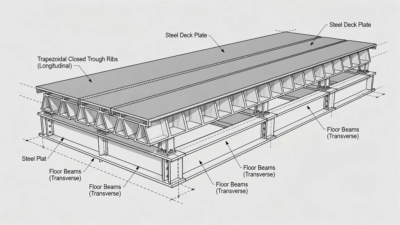
The anatomy of an orthotropic steel deck consists of three primary components working together as an integrated structural system: the deck plate, the longitudinal ribs, and the transverse floor beams. These components are connected by welded joints that must be designed and fabricated with precision to achieve the expected fatigue life.
The deck plate is the flat steel plate that forms the top surface of the orthotropic deck. It directly supports the wearing surface (surfacing system) and transfers wheel loads to the longitudinal ribs below. The deck plate is typically fabricated from AASHTO M270 / ASTM A709 Grade 50 steel with a minimum yield strength of 50 ksi (345 MPa). Higher performance grades such as Grade 50W or HPS 70W may be specified for special applications requiring enhanced toughness or corrosion resistance.
| Design Parameter | FHWA Option #1 | FHWA Option #2 |
|---|---|---|
| Deck plate thickness | 5/8 in. (15.9 mm) | 3/4 in. (19 mm) |
| Maximum rib span | 15 ft (4.6 m) | 18 ft (5.5 m) |
| Recommended rib type | Closed or open | Closed or open |
| Panel flatness tolerance | 1/8 in. over 10 ft | 1/8 in. over 10 ft |
The deck plate thickness is a critical design parameter because it directly controls the magnitude of localized bending stresses at the rib-to-deck weld location. Thicker deck plates reduce the localized bending stress amplitude under wheel loads, extending the fatigue life of the welded connection. Research by the FHWA Turner-Fairbank Highway Research Center and the Japan Public Works Research Institute (PWRI) has demonstrated that deck plate thickness is the single most influential geometric parameter controlling fatigue crack initiation at the rib-to-deck weld. The San Mateo-Hayward Bridge in California used a 3/4 in. (19 mm) deck plate that lasted 47 years before requiring significant fatigue repairs, while the Danziger Bridge with a thinner 1/2 in. (12.7 mm) deck plate experienced accelerated surfacing cracking and fatigue distress.
Longitudinal ribs are the primary stiffening elements that run parallel to the bridge axis. They are welded to the underside of the deck plate and transfer loads to the transverse floor beams. Two types of ribs are used: closed ribs and open ribs.
Closed ribs, also called trough ribs or trapezoidal ribs, have a U-shaped or trapezoidal cross-section formed by bending a flat steel plate. They are the dominant rib type in modern orthotropic decks because of their superior torsional rigidity, which provides better load distribution between adjacent ribs and allows the deck plate to span greater distances between floor beams. The trapezoidal shape — with inclined sides at approximately 72 degrees from horizontal — is preferred over a pure U-shape because it simplifies fabrication, reduces the required bend radius, and provides a more efficient cross-section. Typical closed rib dimensions per the FHWA Level 1 design options are:
| Parameter | Closed Rib Option #1 | Closed Rib Option #2 |
|---|---|---|
| Rib depth (A) | 10.5 in. (267 mm) | 14 in. (356 mm) |
| Rib plate thickness | 5/16 in. (8 mm) | 3/8 in. (10 mm) |
| Maximum rib span | 15 ft (4.6 m) | 18 ft (5.5 m) |
| Rib spacing | 2 ft 2 in. (660 mm) | 2 ft 2 in. (660 mm) |
| Bottom flat width | 6.5 in. (165 mm) | 6.5 in. (165 mm) |
| Bend angle (from horizontal) | 72 degrees | 72 degrees |
| Bend radius | 1.5 in. (38 mm) | 1.5 in. (38 mm) |
Closed ribs are welded to the deck plate using partial-joint-penetration (PJP) groove welds applied from the outside of the rib. The weld must achieve minimum 60% penetration of the rib wall thickness per AASHTO LRFD 9th Edition (2020), relaxed from the earlier 70–80% requirement based on extensive fatigue testing. Access to the inside of closed ribs for inspection is provided through handholes — typically 4 in. by 24 in. (100 mm by 610 mm) openings cut in the rib bottom at each floor beam location. These handholes are covered with bolted wire screens after inspection to prevent debris accumulation.
Open ribs are simpler sections — flat plates, bulb-T sections, or rolled angle sections — welded directly to the underside of the deck plate. They require fillet welds on both sides of the rib rather than PJP groove welds, which simplifies fabrication and inspection. However, open ribs lack the torsional rigidity of closed ribs, requiring closer spacing and limiting the maximum floor beam spacing. Typical open rib spacing is approximately 1 ft 3 in. (380 mm) , compared to 2 ft 2 in. for closed ribs. The FHWA Level 1 design options for open ribs specify:
| Parameter | Open Rib Option #1 | Open Rib Option #2 |
|---|---|---|
| Rib depth (A) | 10 in. (254 mm) | 12 in. (305 mm) |
| Rib plate thickness (B) | 5/8 in. (16 mm) | 3/4 in. (19 mm) |
| Maximum rib span | 10 ft (3.0 m) | 15 ft (4.6 m) |
| Deck plate thickness | 5/8 in. (16 mm) | 3/4 in. (19 mm) |
| Rib spacing | 1 ft 3 in. (380 mm) | 1 ft 3 in. (380 mm) |
Open ribs are easier to field-splice and provide better inspection access to the welded connections. The George Washington Bridge upper deck redecking (1978) used open T-ribs to achieve a 46% weight reduction over the original concrete deck.
Floor beams (also called cross-beams or transverse beams) are the transverse stiffening elements that support the longitudinal ribs at regular intervals and transfer loads from the deck to the main bridge girders. The spacing between floor beams equals the rib span — the distance the longitudinal ribs must span without intermediate support. Floor beams are typically fabricated from built-up plate girders with a web plate and top and bottom flange plates.
The floor beam web is penetrated at each rib location to allow the longitudinal rib to pass through continuously. The connection between the rib and the floor beam web is one of the most fatigue-critical details in the entire orthotropic deck system. Two connection types are used: the fitted connection, where the floor beam web is cut to match the rib contour and fillet-welded to the rib, and the slit or extended cutout connection, where a cutout in the floor beam web under the rib bottom relieves stress concentration. The FHWA recommends the extended cutout connection for new designs based on improved fatigue performance.
Floor beam web thickness is typically 1/2 in. (13 mm) for spans in the 15–18 ft range, with bottom flange thicknesses around 3/4 in. (19 mm) . The web depth below the rib must be at least equal to the rib depth to maintain adequate flexibility for accommodating differential deflections between adjacent ribs.
The primary advantage of orthotropic steel decks is their exceptionally low self-weight. An OSD carries approximately 20–30% of the dead load of an equivalent concrete deck. For a typical 8 in. (200 mm) reinforced concrete deck on 7 ft (2.1 m) girder spacing, the dead load is approximately 100 psf (4.8 kPa). An equivalent orthotropic steel deck with 5/8 in. deck plate and closed ribs weighs approximately 20–25 psf (1.0–1.2 kPa) for the steel alone, plus 20–35 psf (1.0–1.7 kPa) for the surfacing system, for a total dead load of 40–60 psf. This weight reduction translates directly into lower demands on main cables, towers, foundations, and substructure elements in long-span bridges.
Orthotropic decks are the deck system of choice for bridges exceeding approximately 500 m (1,640 ft) in main span length. In suspension bridges, the dead load of the deck represents 60–70% of the total stress in the main cables at the design span lengths of 1,000–2,000 m. Every unit reduction in deck weight reduces cable steel tonnage, tower size, and foundation requirements by a multiple factor. The Akashi Kaikyo Bridge in Japan — the world’s longest suspension span at 1,991 m (6,532 ft) — achieved its record span using an orthotropic steel deck that minimized dead load to levels unattainable with any other deck system.
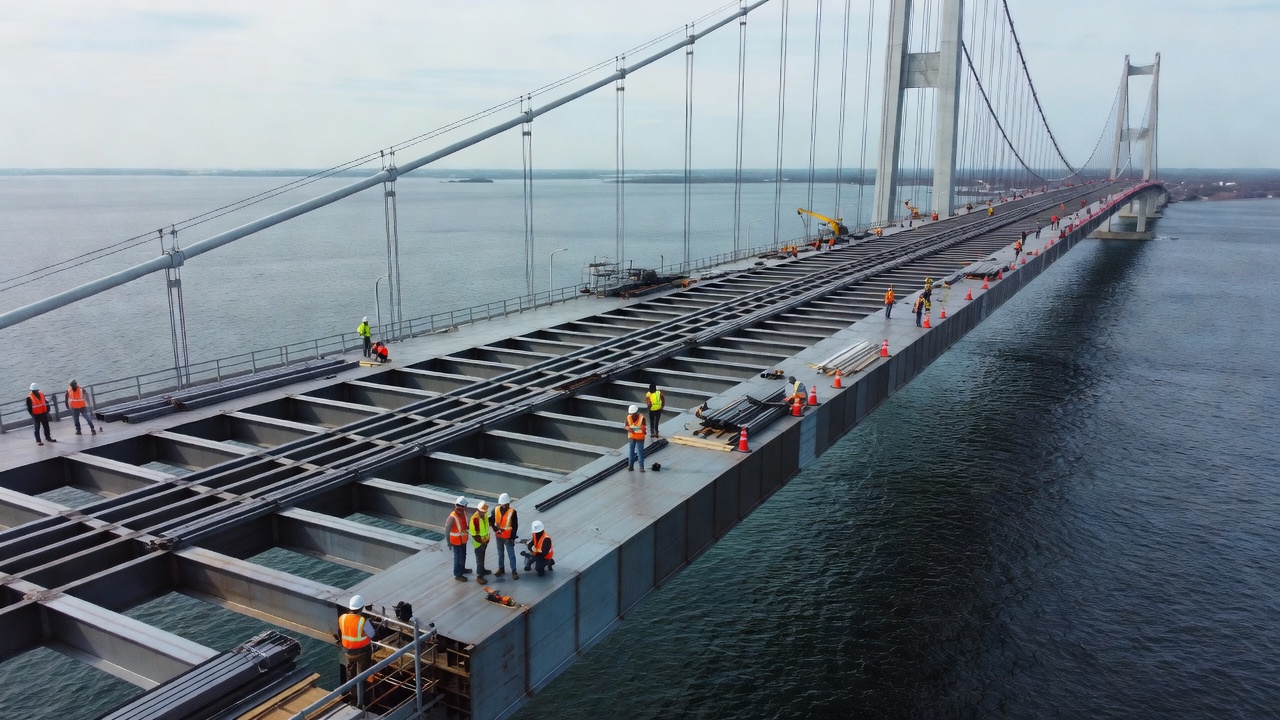
Orthotropic deck panels are fabricated in controlled shop environments with automated welding equipment, ensuring consistent weld quality and dimensional accuracy. Panels are typically fabricated in widths of 10–16 ft (3–5 m) and lengths of 40–60 ft (12–18 m), then transported to the bridge site for erection. The Golden Gate Bridge redecking (1985–1986) replaced 567,000 sq ft of concrete deck with prefabricated orthotropic panels over 401 working days, with all work performed at night on half-width while maintaining daytime traffic. The Macdonald Bridge Big Lift in Halifax, Nova Scotia replaced 46 orthotropic deck sections during night and weekend closures while the bridge remained open for weekday commuter traffic. Shop fabrication reduces field welding by up to 80%, minimizing quality risks associated with field conditions.
The light weight of orthotropic decks reduces seismic inertial forces on the substructure, making them advantageous in high-seismicity regions. The inherent structural redundancy of the ribbed plate system provides multiple load paths — if one rib develops a fatigue crack, the adjacent ribs redistribute the load. This redundancy is formally recognized in the AASHTO LRFD Bridge Design Specifications, which classify orthotropic deck details into fatigue categories based on the number of redundant load paths.
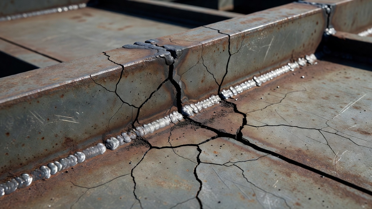
Fatigue cracking is the primary durability concern for orthotropic steel decks. The FHWA classifies fatigue cracks in orthotropic decks into four primary types, each associated with a specific welded connection detail. The FHWA Manual for Repair and Retrofit of Fatigue Cracks in Steel Bridges (FHWA-IF-13-020) provides comprehensive guidance on detection and repair.
Type 1 cracks initiate at the weld toe on the deck plate side of the rib-to-deck fillet weld. They propagate downward through the deck plate thickness under the cyclic bending stress caused by wheel loads passing directly over the rib. The deck plate between ribs acts as a short-span slab subjected to concentrated wheel loads, creating high localized bending stresses. The weld toe acts as a severe stress concentration, with stress concentration factors typically in the range of 2.5 to 4.0 depending on weld profile geometry.
Type 1 cracks are detectable from the top surface after surfacing removal using magnetic particle testing (MT) or dye penetrant testing (PT) , or from below using ultrasonic testing (UT) . The crack growth rate follows Paris law propagation through the deck plate thickness, which is typically 5/8 in. to 3/4 in. (16–19 mm). Once the crack penetrates the full deck plate thickness, it may propagate longitudinally along the weld line, potentially causing surfacing failure and water intrusion.
Type 2 cracks initiate at the weld root of the partial-joint-penetration fillet weld that connects the rib to the deck plate. The incomplete joint penetration — which by design leaves an unwelded gap at the root — acts as a built-in crack tip. Under cyclic loading, this root crack may propagate in two distinct paths: Type A1 propagates upward through the deck plate toward the top surface, while Type A3 propagates through the weld throat along the fusion face.
Root cracks are particularly dangerous because they can propagate undetected from the underside until they break through the top surface of the deck plate, at which point water intrusion and accelerated corrosion occur. Japanese research by the PWRI has shown that root cracks may arrest at approximately 75% of deck plate thickness under certain stress conditions, but can also propagate to full-thickness fracture under high traffic volumes. The AASHTO LRFD specification now requires 60% minimum weld penetration (relaxed from 80%) based on research showing that moderate reductions in penetration do not significantly reduce fatigue life, while the associated relaxation of welding requirements improves production quality and reduces the incidence of blow-through defects.
Type 3 cracks occur at the intersection of the rib web and floorbeam web, specifically at the cutout — the opening in the floorbeam web through which the rib passes. The cutout creates a severe geometric stress concentration, exacerbated by out-of-plane distortion of the floorbeam web as adjacent ribs deflect differently under truck wheel loads. This differential deflection creates a Vierendeel-type frame action at the rib-floorbeam intersection, generating high secondary stresses.
Type 3 cracks initiate at the cutout edge and propagate into the floorbeam web, often following the weld toe of the rib-to-floorbeam fillet weld. This was the dominant cracking mode observed on early orthotropic decks including the Severn Bridge (UK, opened 1966) and the Forth Road Bridge (Scotland, opened 1964), both of which required extensive strengthening programs in the 1970s–2000s. Retrofit measures for Type 3 cracking include cutout geometry modification (increasing the cutout radius to reduce stress concentration), internal bulkhead installation at cutouts, and post-tensioning of the floorbeam web.
Type 4 cracks propagate in the rib web itself adjacent to the rib-to-floorbeam weld, often near the cutout termination. They are caused by the combined action of vertical shear transfer between rib and floorbeam, plus out-of-plane bending of the rib wall at the connection. These cracks propagate vertically or at an inclined angle, and can grow to lengths of several inches before detection.
The wearing surface on an orthotropic steel deck serves multiple critical functions beyond providing a skid-resistant driving surface. It distributes concentrated wheel loads laterally across the deck plate, reducing localized bending at the rib-to-deck weld by 30–50% . It waterproofs the steel plate to prevent corrosion, and it provides a smooth riding surface that protects the steel from abrasion and impact. Without surfacing, the deck plate would be subjected to directly applied wheel loads that would produce unacceptably high local bending stresses.
Mastic asphalt, known as Gussasphalt in Germany, is the most established surfacing system for orthotropic decks in Europe. It is a high-sand-content, fine-graded asphalt concrete with a high binder content (12–14% bitumen by weight) that is applied hot and self-compacting. The material is floated and screeded to finished grade without compaction rolling, achieving an impermeable surface that bonds directly to a primed steel deck.
Mastic asphalt is applied at a finished thickness of 1.5–2.5 in. (35–65 mm) and does not require a separate waterproofing membrane in most applications. The system was developed in Germany in the 1950s and has been used on over 400 orthotropic bridge decks in Europe, including the Severn Bridge and the approach spans of the Millau Viaduct (France, 2004). The primary failure modes are rutting in hot weather, embrittlement at low temperatures leading to cracking, and loss of bond at the steel interface.
Epoxy asphalt is a two-component thermosetting binder mixed with selected aggregates that cures by chemical reaction rather than cooling. It provides extremely high strength, excellent bond to steel, creep resistance at high temperatures, and resistance to fuel and oil spills. The ChemCo Systems proprietary epoxy asphalt formulation has been used on orthotropic decks since the 1960s, with over 40 years of proven performance.
The Golden Gate Bridge redecking (1985–1986) used a two-layer epoxy asphalt system: a 1/4 in. (6 mm) epoxy seal coat applied in the shop, followed by a 2 in. (50 mm) epoxy asphalt wearing course placed in the field. The total system weight is approximately 28 psf (1.34 kPa). Application requires precise temperature control — the epoxy resin and curing agent are mixed at elevated temperature and placed at 200–250°F (93–121°C), with curing time of 24–72 hours before traffic may be permitted.
Thin polymer overlays — typically Polymer-Methyl Methacrylate (PMMA) , polyurethane, or polyester systems — are applied at thicknesses of 0.25–0.5 in. (6–12 mm) and weigh only 3–8 psf (0.14–0.38 kPa). They cure rapidly (1–4 hours), allowing overnight installation and reopening to traffic the same day. However, they provide less load distribution than thicker asphalt systems and have a shorter service life of 8–15 years compared to 20–30+ years for epoxy asphalt. They are sensitive to surface preparation and application conditions, requiring near-white metal blast cleaning (SSPC-SP10/NACE No. 2) and strict temperature and humidity control during application.
Polymer-modified bitumen systems incorporate SBS (styrene-butadiene-styrene) or EVA (ethylene-vinyl-acetate) polymers to improve high-temperature rut resistance and low-temperature flexibility. They require a separate spray-applied or sheet-applied waterproofing membrane between the steel deck and the wearing course. Applied thickness is typically 1.5–2.5 in. (40–65 mm), similar to conventional mastic asphalt.
| Surfacing System | Typical Thickness | Weight (psf) | Service Life | Cure Time |
|---|---|---|---|---|
| Mastic Asphalt | 1.5–2.5 in. | 20–35 | 15–25 years | 2–4 hours |
| Epoxy Asphalt | 1.5–2.0 in. | 20–28 | 20–30+ years | 24–72 hours |
| Polymer-Modified Bitumen | 1.5–2.5 in. | 20–35 | 10–20 years | 2–6 hours |
| Thin Polymer Overlay | 0.25–0.5 in. | 3–8 | 8–15 years | 1–4 hours |
Inspection of welded connections in orthotropic steel decks requires specialized non-destructive testing (NDT) methods governed by the AWS D1.5/D1.5M Bridge Welding Code and AASHTO LRFD Bridge Construction Specifications. The confined geometry inside closed trapezoidal ribs and the complex stress fields at rib-to-floorbeam connections demand carefully adapted inspection procedures.
Visual inspection is the first-line NDT method and is required 100% for all welds per AWS D1.5. The inspector must hold AWS Certified Welding Inspector (CWI) certification and use a minimum 4x magnification for crack detection, with 10x recommended for fine surface crack detection. Lighting at the inspection surface must be at least 50 foot-candles (538 lux). For rib-to-deck welds inside closed ribs, access is through the handholes cut in the rib bottom at each floor beam location — typically 4 in. by 24 in. openings spaced at 15–18 ft intervals. A borescope or inspection mirror is used to view the inaccessible portions of the weld. Inspection must be performed before, during, and after welding to detect hot cracking, lack of fusion, undercut, porosity, and slag inclusion.
Conventional ultrasonic testing uses single-element transducers operating at 2.25–10 MHz to introduce sound waves into the weld and detect reflections from internal discontinuities. Calibration per AWS D1.5 Annex VII uses IIW (International Institute of Welding) type reference blocks. Angle beams at 45°, 60°, and 70° are used for shear wave inspection of groove welds. For orthotropic deck welds, conventional UT is limited by access constraints inside closed ribs and the difficulty of discriminating between root geometry and actual crack indications.
Phased Array Ultrasonic Testing (PAUT) is the preferred method for rib-to-deck weld inspection and was formally recognized by AWS D1.5 in the 2015 edition. PAUT uses a multi-element probe (typically 16–128 elements) that electronically steers the ultrasonic beam through a range of angles (35°–75°) from a single probe position. The resulting sectorial scan (S-scan) shows the full weld cross-section in real time, allowing the operator to visualize the weld geometry, penetration depth, and any internal discontinuities. PAUT has demonstrated superior probability of detection for both weld toe and weld root cracks in rib-to-deck connections compared to conventional UT.
The FHWA has developed tailored PAUT procedures for orthotropic deck inspection (Report FHWA-HRT-24-010) specifying a 5 MHz, 32-element array with 0.6 mm element pitch, using a custom wedge designed to fit inside the trapezoidal rib geometry. Calibration is performed using notches in production-representative specimens, and the system can reliably detect root cracks of 1 mm or greater. PAUT operators must have a minimum of 100 documented hours of bridge-specific PAUT experience per AASHTO requirements.
Magnetic particle testing is the primary method for detecting surface and near-surface fatigue cracks at rib-to-floorbeam connections and cutout regions. An AC electromagnetic yoke is the preferred magnetization method — it induces a magnetic field between two poles placed on either side of the weld, and fine iron particles (dry visible powder or wet fluorescent suspension) are applied to reveal magnetic flux leakage at crack locations. AC yoke inspection concentrates the magnetic flux at the surface (skin effect), optimizing sensitivity to fine surface fatigue cracks with detection limits as small as 0.001 in. (0.025 mm) crack width.
All rib-to-floorbeam fillet welds are typically inspected 100% by MT during initial fabrication and during in-service inspection. The yoke is positioned in two perpendicular orientations to detect cracks in all directions — cracks perpendicular to the weld line and cracks parallel to it. DC yokes are sometimes used for deeper penetration when subsurface defects are suspected, but AC yokes are preferred for surface crack detection on in-service orthotropic decks.
| Weld Type | Primary NDT Method | Secondary Method | Frequency |
|---|---|---|---|
| Rib-to-Deck (RD) fillet | PAUT | VT (100%) | 100% production |
| Rib-to-Floorbeam (RF) fillet | MT | VT (100%) | 100% production |
| Deck plate butt splice | PAUT or RT | VT + MT | 100% production |
| Rib splice (butt weld) | PAUT or RT | VT + MT | 100% production |
| Field splices | PAUT or RT | VT + MT | 100% field welds |
In-service detection of fatigue cracks in orthotropic decks requires a systematic approach combining visual inspection of accessible welds, targeted NDT of known fatigue-prone details, and monitoring of surfacing condition as an indicator of underlying deck cracking. Cracks that propagate to the deck plate top surface may be indicated by surfacing cracks appearing directly over the rib-to-deck weld lines — these reflective cracks are often the first visible sign of deck plate cracking.
For inspection inside closed ribs, specialized miniaturized UT probes and borescopes are used. Some bridge owners have deployed crawler robots with cameras and NDT sensors that navigate inside closed trapezoidal ribs, providing remote inspection capability without requiring personnel entry into confined spaces. The confined space entry classification of closed ribs (typically less than 24 in. clear height) requires atmospheric testing, ventilation, and rescue planning per OSHA 29 CFR 1910.146.
The FHWA Manual for Repair and Retrofit of Fatigue Cracks in Steel Bridges categorizes repair methods by crack severity and location.
Surface treatments for weld toe cracks (Type 1) without full-thickness propagation include disc grinding to remove surface defects up to 0.5 mm depth, burr grinding for deeper removal (1–2 mm), and Ultrasonic Impact Treatment (UIT) — currently the most effective preventive and repair method for weld toe cracking. UIT uses a high-frequency (20–40 kHz) impacting tool that plastically deforms the weld toe surface, introducing beneficial compressive residual stresses that retard crack initiation and propagation.
Through-thickness crack repair methods include hole drilling (stop holes) at each crack tip — drilling a 3/4–1 in. (19–25 mm) diameter hole using annular cutters, verifying complete crack tip removal with MT or PT. For longer cracks, the vee-and-weld method uses air-arc gouging to remove the cracked metal, followed by grinding and rewelding with low-hydrogen welding processes. For locations where rewelding is impractical, bolted doubler or splice plates using high-strength bolts may be installed to restore the load path across the cracked section. Carbon Fiber Reinforced Polymer (CFRP) patches bonded across cracked zones are increasingly used, particularly for rib-to-deck weld fatigue repair, providing stiffness restoration without introducing new welded details.
Orthotropic steel decks are used in many of the world’s most notable long-span bridges. The following table summarizes key installations:
| Bridge | Country | Year | Type | Main Span (ft) | Rib Type | Surfacing |
|---|---|---|---|---|---|---|
| Akashi Kaikyo Bridge | Japan | 1998 | Suspension | 6,532 | Trapezoidal closed | Epoxy asphalt |
| Severn Bridge | UK | 1966 | Suspension | 3,240 | Trapezoidal closed | Mastic asphalt |
| Forth Road Bridge | UK | 1964 | Suspension | 3,300 | Trapezoidal closed | Polymer-modified asphalt |
| Golden Gate Bridge (redecked) | USA | 1985 | Suspension | 4,200 | Trapezoidal closed | Epoxy asphalt |
| Millau Viaduct | France | 2004 | Cable-stayed | 1,122 (max) | Trapezoidal closed | Mastic asphalt |
| San Fran-Oakland Bay (SAS) | USA | 2013 | Self-anchored susp. | 1,263 | Trapezoidal closed | Epoxy asphalt |
| George Washington (redecked) | USA | 1978 | Suspension | 3,500 | Open T-ribs | Bituminous |
| Benjamin Franklin (redecked) | USA | 1987 | Suspension | 1,750 | Open bulb sections | Epoxy + bituminous |
| Lions Gate Bridge | Canada | 1975 | Suspension | 1,550 | Trapezoidal closed | Polymer-modified |
| Macdonald Bridge | Canada | 1990s | Suspension | ~1,700 | Trapezoidal closed | Asphalt |
The Severn Bridge was the world’s first major orthotropic box girder deck, pioneering the aerodynamic deck cross-section that became standard for subsequent long-span suspension bridges. The Akashi Kaikyo Bridge achieves the world’s longest suspension span using an orthotropic deck whose low dead load was essential to reaching 1,991 m between towers — at this scale, every ton of deck weight requires approximately 3–4 tons of cable steel. The Millau Viaduct contains the largest orthotropic deck area of any single bridge at 1,989,168 sq ft (184,800 m²), spanning eight cable-stayed segments across the Tarn Valley in France.
The Golden Gate Bridge redecking project replaced the original 1937 concrete deck with prefabricated orthotropic panels weighing 46% less, reducing dead load from 104 psf to 56 psf for the steel panel alone. The entire 567,000 sq ft replacement was completed in 401 working days with all work performed at night on half-width closures, keeping all traffic lanes open during daytime hours.
Structural Health Monitoring (SHM) of orthotropic steel decks provides continuous or periodic assessment of fatigue crack development, stress cycles, and structural performance. The FHWA and European highway authorities have developed comprehensive monitoring programs for orthotropic decks approaching their design fatigue life.
Resistive foil strain gauges mounted on the deck plate at rib-to-deck weld toes and on rib webs near rib-to-floorbeam connections provide direct measurement of local stress amplitudes under traffic loading. Long-gauge fiber optic sensors (Fiber Bragg Grating — FBG) offer advantages for orthotropic deck monitoring because they measure average strain over gauge lengths of 100–500 mm, capturing distributed behavior rather than point stresses. FBG sensors can be embedded between the steel plate and the wearing surface to measure deck plate bending strains, bonded along rib webs to detect crack initiation through strain profile changes, or multiplexed along a single fiber optic cable running inside closed ribs.
Acoustic Emission (AE) monitoring is one of the most effective methods for real-time fatigue crack detection in orthotropic decks. Piezoelectric sensors mounted at known fatigue-prone details detect the stress waves released when a crack propagates under traffic loading. The Dutch highways authority Rijkswaterstaat has conducted long-term AE monitoring on orthotropic bridges including the Hollandse Brug and Galecopperbrug, correlating crack growth rates with weigh-in-motion (WIM) traffic data. AE monitoring can localize crack activity within a few inches using sensor arrays and can discriminate between active crack propagation and environmental noise through signal frequency analysis and amplitude distribution (b-value analysis).
Accelerometer networks measuring natural frequencies and mode shapes of individual deck panels can detect overall stiffness loss from accumulated fatigue damage. Changes in local mode shapes indicate damage location, and shifts in natural frequency of 5–10% typically indicate significant crack development. Vibration monitoring is complementary to AE and strain monitoring — it detects the global effect of damage while AE detects the local propagation events.
Unmanned Aerial Vehicles (UAVs) with high-resolution cameras (4K+) and thermal imaging sensors are increasingly used for visual inspection of orthotropic deck undersides, eliminating the need for under-bridge inspection vehicles and lane closures in many cases. Drones can survey the condition of rib-to-floorbeam connections and cutouts, detect corrosion and coating failure, and identify surfacing defects on the deck top surface through thermal imaging. Miniaturized drones are being developed for deployment inside closed trapezoidal ribs, though confined access remains challenging.
A typical SHM system for an orthotropic deck combines strain gauges at critical weld details, AE sensor clusters at known crack-prone locations (particularly rib-to-floorbeam cutouts), accelerometers on deck panels, and temperature sensors for thermal effect separation. Data is transmitted via cellular or fiber optic link to a central processing platform that applies threshold-based alerts and trend analysis. Typical alert thresholds include strain range exceeding the AASHTO Category C constant amplitude fatigue limit, AE hit rate exceeding 5 hits per truck pass sustained over one month, natural frequency shift exceeding 5%, and crack growth rate exceeding 0.01 in. per month for detected cracks.
Design, fabrication, inspection, and maintenance of orthotropic steel decks are governed by the following primary standards and references:
Orthotropic steel decks represent a mature, high-performance bridge deck technology that enables the longest bridge spans in the world. Their successful application requires meticulous attention to weld detail design, fabrication quality control, surfacing system selection and application, and systematic in-service inspection and monitoring programs tailored to the unique fatigue behavior of the rib-to-deck and rib-to-floorbeam connections.
TarmacView provides expert inspection and structural evaluation services for orthotropic steel bridge decks, including drone-based visual surveys, fatigue crack detection, and structural health monitoring. Contact our team for a consultation.
The bridge deck is the uppermost structural element of a bridge, directly supporting traffic loads and providing the riding surface. Deck condition — cracking, ...
Bridge girders are the primary horizontal load-carrying beams supporting the bridge deck, spanning between piers and abutments. Common types include steel I-gir...
A box girder is a hollow, closed-section bridge girder of steel or concrete that provides high torsional stiffness and efficiency for curved or long-span bridge...