Pavement cores are cylindrical specimens extracted from in-service pavements for laboratory evaluation of layer thickness, density, air voids, binder content, compressive strength, layer bonding, and distress depth. Core data provides definitive ground truth for forensic investigations, quality control, and pavement condition assessment.
Definition and Purpose in Forensic Investigation
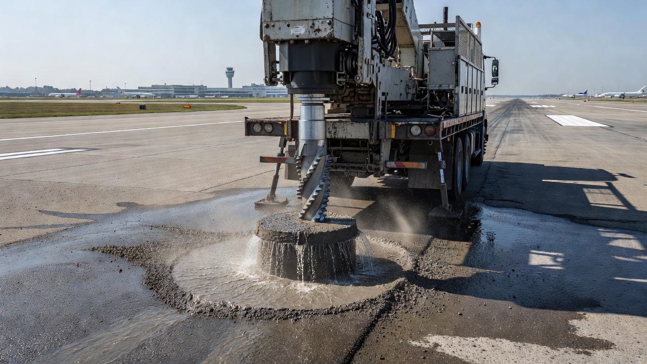
A pavement core is a cylindrical specimen of pavement material extracted by rotary drilling using a core drill fitted with a diamond-tipped or hardened steel core bit. The core preserves the full vertical profile of the pavement structure — from the surface course through the base and, when the pavement is thin, into the subgrade. Pavement cores are the single most valuable source of definitive forensic evidence because they provide direct physical measurements of material properties that surface inspection can only estimate.
The purpose of pavement core extraction in a forensic investigation is to validate or refute hypotheses developed from visual condition surveys. Surface distress patterns — cracking, rutting, raveling, bleeding, patching — each have multiple potential root causes. A core sample reveals the actual cause by exposing the material condition at depth. For example, a surface crack observed on inspection may be caused by fatigue failure from excessive tensile strain at the bottom of the asphalt layer, by reflective cracking from an underlying cement-treated base, or by thermal contraction. Layer thickness measured on a core tells the engineer which of these mechanisms is active. If the asphalt layer is too thin relative to the design thickness, the crack is almost certainly structural fatigue. If the thickness is adequate, the cause is more likely thermal or reflective.
Core data forms the ground truth for calibrating and verifying all non-destructive testing (NDT) methods used in pavement evaluation. Ground Penetrating Radar (GPR) estimates of layer thickness require validation through cores — GPR signal velocity assumptions are adjusted based on actual thickness measurements. Falling Weight Deflectometer (FWD) backcalculated layer moduli are compared against laboratory-measured moduli from core specimens. Nuclear density gauge readings of in-place asphalt density are correlated against bulk specific gravity measured on extracted cores. Without core calibration, NDT results remain mathematically computed estimates without physical verification.
The FHWA Long-Term Pavement Performance (LTPP) program, the largest pavement performance study ever conducted, relies on standardized core sampling protocols for all its test sections. The LTPP Distress Identification Manual specifies core sample requirements for every distress type investigation — rutting trenches, fatigue cracking verification, thermal cracking depth measurement, and patching evaluation. The program’s data shows that surface-identified distress severity does not always correlate with in-depth material condition, underscoring why cores are indispensable.
Coring Equipment
Pavement coring requires specialized equipment capable of cutting through hard, abrasive pavement materials while maintaining sample integrity. The three essential components of any coring operation are the core drill (rig), the core bit, and the cooling system.
Core Drill Rigs
Core drills range from lightweight hand-held units used for small-diameter concrete cores to truck-mounted hydraulic rigs capable of extracting 150 mm or larger cores through full-depth asphalt and concrete pavements. For most pavement investigation work, a trailer-mounted or truck-mounted coring rig with a gasoline, diesel, or hydraulic power unit is standard. The rig must provide sufficient rotational torque and downward feed pressure to maintain a steady penetration rate without binding or overheating the bit.
The rig must be mounted on a stable platform that can be leveled on the pavement surface to ensure the core barrel enters perpendicular to the pavement surface. A deviation from perpendicular of more than 5 degrees can cause the core to fracture during extraction or produce a specimen with non-parallel ends that requires capping or grinding before testing. Most coring rigs include a leveling mechanism with adjustable feet and built-in bubble levels.
Diamond Core Bits
The core bit is the cutting tool and is the most critical component of the coring system. For pavement coring, the bit is a hollow steel barrel with diamond-impregnated segments brazed or laser-welded to the cutting end. The diamonds are industrial-grade synthetic diamonds embedded in a metal matrix. The matrix hardness is matched to the pavement material being cored — softer matrix for hard aggregates (the matrix wears away to expose fresh diamonds) and harder matrix for soft aggregates (to prevent premature diamond loss).
Core bits are available in open-head and closed-head styles. Open-head bits have a continuous barrel with the cutting segments at the bottom — these are used when the core is to be removed from the top of the barrel after drilling. Closed-head bits have a removable inner barrel (core barrel liner) that allows the core to be extracted without flipping the drill rig. For pavement investigation, open-head bits are more common because they allow direct visual observation of the core during extraction.
Core bit diameters range from 50 mm (2 inches) to 200 mm (8 inches), with 100 mm (4 inches) being the standard for most pavement testing applications. ASTM D5361 specifies a minimum diameter of 100 mm for compacted asphalt mixture cores. For concrete pavement cores tested per ASTM C42, the preferred diameter is 100 mm, though 50 mm cores can be used when the nominal maximum aggregate size is 25 mm or less. Larger diameters (150 mm) are specified when testing for dynamic modulus (AASHTO T342) or when the core will be used for multiple test procedures requiring substantial material volume.
Core bit length determines the maximum depth of extraction. Standard bits are 300 mm to 450 mm long, sufficient for most pavement structures. For deep coring through full-depth asphalt over thick granular base layers, extension barrels can be added to reach depths of 1,000 mm or more.
Water Cooling System
Continuous water cooling is essential during coring. Water serves three critical functions: cooling the diamond segments (friction generates intense heat that can damage the diamonds and the bit matrix), lubricating the cutting interface to reduce friction, and flushing cuttings away from the cutting face. Without adequate water flow, the bit will overheat, the diamonds will glaze or pull out, and the bit will stop cutting effectively.
The water supply must deliver a consistent flow rate of approximately 5 to 15 liters per minute depending on bit diameter and drilling conditions. The water is typically supplied from a tank mounted on the coring rig. In cold climates, a small amount of windshield washing fluid or isopropyl alcohol can be added to the water to prevent freezing. Water flow should be directed around the full circumference of the bit, not as a single stream.
Some automated coring systems use dry coring with vacuum extraction of dust, but this method is less common for pavement investigation because of the increased risk of heat damage to the core sample and the bit.
Core Extraction Procedure
The extraction procedure follows a defined sequence. The rig is positioned over the marked core location and leveled. The drill is activated and the bit is lowered slowly — the initial contact must be gentle to prevent the bit from skipping or walking across the pavement surface. Once the bit has established a groove, the feed pressure and rotation speed are increased to the optimal rate for the pavement material.
For asphalt pavement, rotation speeds of 300 to 600 RPM with moderate feed pressure are typical. For concrete pavement, speeds of 200 to 400 RPM with reduced feed pressure are used because concrete is harder and more abrasive. The operator monitors the drilling sound and feel — a change in sound often indicates the bit has passed through a layer interface into a different material.
When the bit reaches the target depth, the operator stops downward pressure while maintaining rotation, then slowly withdraws the bit. The core typically remains inside the barrel. The core is removed by lifting it out with a core extractor tool or by tilting the rig and sliding the core out onto a clean surface. The core is immediately labeled with the project identifier, core number, location, date, and orientation (top surface marked with an arrow).
Core Location Selection
Core location selection is a statistically and scientifically guided process that directly affects the validity of the investigation conclusions. The wrong core locations can produce misleading data that leads to incorrect rehabilitation decisions. Core locations are selected based on the type and purpose of the investigation.
Forensic Investigation — Paired Sampling
For forensic investigations, the standard approach is paired sampling: cores are taken from both distressed areas and adjacent sound pavement areas. The sound-area core serves as the control specimen. Comparing the properties of the distressed core against the control core isolates the material factors that contributed to the distress. For example, if the distressed core shows 8% air voids while the control core shows 4% air voids, the higher air void content in the distressed area is a probable contributing factor to the observed cracking or raveling.
The FHWA LTPP Forensic Investigation Framework specifies detailed core location protocols for each distress type:
Distress Type
Core Location Strategy
Number of Cores
Fatigue cracking
Through crack center + adjacent sound area
3 per section
Rutting
Rut wheel path + between wheel paths
2 per lane
Thermal cracking
Through crack + 300 mm from crack
2 per crack
Raveling
At raveled edge + sound area 1 m away
2 per area
Patching
Through patch center + adjacent original pavement
2 per patch
Quality Control and Acceptance Testing
For construction quality control, core locations are determined using a random sampling plan to avoid selection bias. ASTM D5361 explicitly cautions against deviating from the random sampling plan in statistically based quality control programs, even when visual inspection identifies areas that appear suspect. The random plan ensures that the test results correctly represent the entire paved area, not just the visually anomalous locations.
The sampling frequency for QC coring is specified in the project specifications. Typical frequencies are one core per 500 to 1,000 square meters for density and thickness acceptance testing. For airport pavements, FAA AC 150/5370-10H specifies the sampling frequency based on the quantity of material placed — typically one core per day’s production or per 500 tons of asphalt mix.
Distressed versus Sound Area Selection
When selecting specific distressed areas for coring, the inspector must classify the distress type before coring. A core taken through the center of a longitudinal crack will confirm whether the crack extends through the full asphalt layer or is limited to the surface. A core taken at a transverse crack will reveal whether the crack is reflective (propagating from an underlying layer) or thermal (initiating at the surface).
Core locations should be clearly documented with photographs, GPS coordinates, station and offset measurements, and a sketch showing the position relative to visible distress features. The documentation should be sufficient for a future investigator to locate the exact core position years later.
Asphalt Core Testing
Once asphalt cores arrive at the laboratory, they undergo a battery of tests that reveal the material properties of each pavement layer and the quality of interlayer bonds.
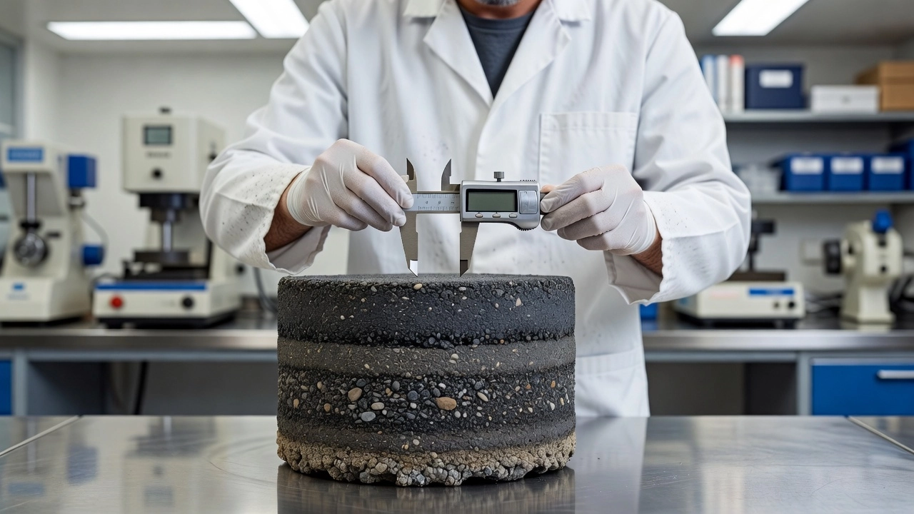
Layer Thickness — ASTM D3549
The first and most fundamental measurement is layer thickness. ASTM D3549/D3549M (Standard Test Method for Thickness or Height of Compacted Asphalt Mixture Specimens) specifies the procedure. For cylindrical cores, four measurements are taken at approximately quarter points on the periphery of the core using a caliper accurate to 0.1 mm. The four measurements are averaged to obtain the mean thickness.
If the core consists of multiple lifts (e.g., a wearing course, a binder course, and a base course), the layer interfaces must be identified and each layer thickness measured separately. Layer interfaces are visually distinguishable by changes in aggregate size, color, or the presence of a tack coat residue line. When interfaces are not clearly visible, the laboratory may use a high-resolution scanner or X-ray imaging to identify layer boundaries.
Measured thickness is compared against the design thickness specified in the construction documents. A thickness deficiency of more than 10% is generally considered significant and may trigger a pay adjustment or require structural evaluation.
Bulk Specific Gravity and Density — ASTM D2726
Bulk specific gravity (Gmb) of the core is determined by the saturated surface-dry (SSD) method per ASTM D2726. The core is dried to constant mass, weighed dry, then submerged in water to measure the submerged mass. The core is then removed, the surface moisture is blotted to a saturated surface-dry condition, and the SSD mass is measured. Bulk specific gravity is calculated as:
Gmb = Dry Mass / (SSD Mass — Submerged Mass)
The in-place density is then calculated by multiplying the bulk specific gravity by the density of water (1,000 kg/m³ or 62.4 lb/ft³). The measured density is compared to the target maximum theoretical density (TMD) determined from the same mix per ASTM D2041 (Rice method). Percent compaction is calculated as:
% Compaction = (In-Place Density / TMD) × 100
Typical acceptance criteria for asphalt pavement compaction are 92% to 96% of TMD, depending on the project specifications and the pavement layer. For airport pavements, FAA specifications require 96% to 98% of TMD for surface courses.
Air Voids Content — ASTM D3203
Air voids in the compacted asphalt mixture are calculated from the bulk specific gravity and the theoretical maximum specific gravity using ASTM D3203:
Air Voids (%) = [1 — (Gmb / Gmm)] × 100
Where Gmm is the theoretical maximum specific gravity of the paving mixture (measured per ASTM D2041 on loose mix sampled during construction).
Air voids are the single most important compaction quality indicator. Optimum air voids for newly constructed asphalt pavements are in the range of 3% to 7%. Air voids below 3% indicate over-compaction, which can lead to flushing (bleeding) of asphalt binder to the surface, reducing skid resistance. Air voids above 7% indicate inadequate compaction, allowing water and air to penetrate the mixture, accelerating oxidative aging and moisture damage. Air voids above 8% significantly increase the risk of premature pavement failure by reducing the mixture’s resistance to fatigue cracking and rutting.
For forensic investigations, the vertical distribution of air voids within the core can be measured by cutting the core into 25 mm thick slices and testing each slice individually. This reveals whether poor compaction is concentrated at the surface, at depth, or at layer interfaces.
Binder Content — AASHTO T308
Asphalt binder content (the percentage of asphalt cement by weight of total mix) is determined by the ignition oven method per AASHTO T308 (ASTM D6307). The core is broken down into individual particles (not crushed) and placed in a furnace at 540°C. The binder is burned off, leaving the mineral aggregate. The mass loss is corrected for the aggregate moisture loss and for the aggregate ignition loss correction factor (determined during mix design). Binder content is calculated as the corrected mass loss divided by the original sample mass.
Binder content is compared to the job mix formula (JMF) target value. Tolerances are typically ±0.3% to ±0.5% of the target, depending on the agency specification. A binder content that is too high can cause bleeding, rutting, and reduced skid resistance. A binder content that is too low results in a dry, brittle mixture prone to raveling, cracking, and moisture damage.
After the binder is removed, the aggregate gradation of the recovered aggregate can be determined by sieve analysis (ASTM C136). The recovered gradation is compared to the JMF gradation band. Significant deviations indicate aggregate segregation or mix production issues.
Layer Bond Strength
The bond strength between adjacent asphalt lifts is a critical performance factor that is often overlooked. A poorly bonded overlay behaves structurally as two independent thin layers rather than one composite thick layer, resulting in significantly reduced fatigue life.
Bond strength is typically measured using the direct shear test or the pull-off tension test (ASTM C1583 modified for asphalt). In the direct shear test, the core is placed in a shear testing apparatus and a horizontal load is applied at the interface plane until failure. The peak shear stress at failure is recorded as the bond strength.
Bond Quality
Shear Strength (MPa)
Interpretation
Excellent
> 1.0
Full bond — overlay behaves as monolithic
Good
0.7 — 1.0
Adequate bond for normal traffic
Fair
0.4 — 0.7
Reduced fatigue life expected
Poor
0.2 — 0.4
Likely debonding under traffic — rehabilitation needed
Failed
< 0.2
Complete delamination — layers are independent
A core that separates at the interface during extraction is direct evidence of bond failure. No laboratory testing is needed — the bond is zero.
Concrete Core Testing
Concrete pavement cores require different testing procedures than asphalt cores. Concrete is a brittle, rigid material, and the testing focuses on structural capacity, material integrity, and durability indicators.
Thickness Measurement — ASTM C174
Concrete core thickness is measured per ASTM C174 (Standard Test Method for Measuring Thickness of Concrete Elements Using Drilled Concrete Cores). The length of the core is measured along its axis using a caliper or a length comparator with an accuracy of 0.25 mm. The ends must be clean and free of loose particles before measurement.
For concrete pavements, the measured thickness is compared to the design thickness. ACI 318 requires that the average measured thickness be at least the design thickness and that no individual measurement be less than the design thickness minus 6 mm. Thickness deficiencies in concrete pavements are critical because the flexural stress in a concrete slab is inversely proportional to the square of the slab thickness.
Compressive Strength — ASTM C42/C39
Concrete core compressive strength is determined per ASTM C42 (Standard Test Method for Obtaining and Testing Drilled Cores and Sawed Beams of Concrete) with testing per ASTM C39 (Standard Test Method for Compressive Strength of Cylindrical Concrete Specimens).
The core ends must be prepared by grinding or sulfur capping to ensure they are flat, perpendicular to the axis, and parallel to each other within 0.05 mm. The core is then loaded in compression at a rate of 0.25 ± 0.05 MPa/s until failure.
The measured compressive strength is corrected for the length-to-diameter (L/D) ratio. A core with L/D of 2.0 has a correction factor of 1.00. For L/D less than 1.75, the measured strength is multiplied by a correction factor from ASTM C42:
L/D Ratio
Correction Factor
2.00
1.00
1.75
0.98
1.50
0.96
1.25
0.93
1.00
0.87
Core compressive strength is compared to the specified design strength (f’c). ACI 318 provides acceptance criteria for core strength evaluation: if the average core strength from three cores is at least 85% of f’c and no individual core is less than 75% of f’c, the concrete is considered structurally adequate. If these criteria are not met, additional investigation (petrography, in-place load testing) is required.
Petrographic Examination — ASTM C856
Petrographic examination per ASTM C856 (Standard Practice for Petrographic Examination of Hardened Concrete) is the most powerful tool for diagnosing concrete material problems. A petrographer examines a thin section (approximately 25 microns thick) cut from the concrete core under a polarizing light microscope. The examination can identify:
Air-void system parameters — total air content, spacing factor, specific surface (ASTM C457). Proper air entrainment (spacing factor < 0.20 mm) is essential for freeze-thaw durability.
Alkali-Silica Reaction (ASR) — reactive aggregate particles with reaction rims, cracks filled with alkali-silica gel.
Delayed Ettringite Formation (DEF) — ettringite deposits in voids and cracks.
Carbonation depth — the depth of carbonation front measured by phenolphthalein indicator.
Water-cement ratio — estimated from capillary porosity and the degree of hydration.
Cracking patterns — microcrack density, orientation, and width distribution.
Aggregate condition — type, shape, texture, presence of deleterious materials.
Petrography is essential for determining the root cause of concrete pavement distress. A surface crack may be caused by ASR (gel-filled cracks radiating from aggregate particles), by freeze-thaw damage (parallel microcracking near the surface), or by structural overloading (vertical cracking through the full depth).
Chloride Profile — ASTM C1152
Chloride ion penetration is measured for concrete cores extracted from pavements exposed to deicing salts or marine environments. The core is ground in 10 mm to 25 mm depth increments and the powder from each increment is analyzed for acid-soluble chloride content per ASTM C1152.
The chloride profile shows the concentration of chlorides as a function of depth from the surface. The profile is compared to the chloride threshold for corrosion initiation of embedded steel (typically 0.05% to 0.15% by weight of concrete for conventional reinforcement, or 0.2% for prestressed steel). Chloride profiles also allow calculation of the apparent chloride diffusion coefficient, which can be used to estimate the remaining time to corrosion initiation.
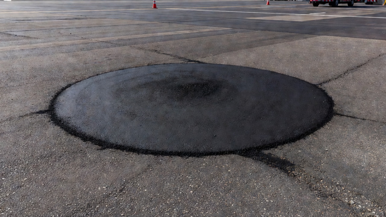
Core Hole Repair
Every core hole creates a discontinuity in the pavement surface that must be repaired immediately to prevent water infiltration, edge spalling, and foreign object debris (FOD) hazards — especially critical on airport pavements.
Asphalt Pavement Core Hole Repair
The repair procedure for asphalt pavement core holes follows these steps:
Clean the hole — remove all drilling slurry, loose aggregate, and water. The hole must be dry before filling. Compressed air is used to blow out any debris.
Apply tack coat — a thin coating of emulsified asphalt tack coat (SS-1h, CSS-1h, or equivalent) is applied to the walls and bottom of the hole to ensure bond between the existing pavement and the patch material.
Backfill with HMA — hot mix asphalt (same mix type as the pavement surface) is placed in lifts. Each lift should not exceed 50 mm in thickness to ensure adequate compaction. For deep holes, multiple lifts are required.
Compact each lift — each lift is compacted using a vibratory plate compactor, a hand tamper, or a special core hole tamping tool. The compaction effort should produce density equivalent to the surrounding pavement.
Finish flush — the final lift is placed slightly above the pavement surface and compacted flush. The finished patch should be level with the surrounding pavement with no depression or bump. A 3 mm tolerance is typical.
Seal the edges — a thin bead of hot asphalt or crack sealant is applied around the perimeter of the patch to prevent water intrusion.
For temporary repairs, cold mix or proprietary patching materials can be used, but the patch must be inspected before the pavement is opened to traffic and replaced with a permanent repair within 30 days.
Concrete Pavement Core Hole Repair
For concrete pavement:
Clean and dry the hole — remove all drilling residue and standing water.
Apply bonding agent — a cementitious bonding agent or epoxy bonding compound is applied to the hole walls.
Fill with patching concrete — rapid-setting patching concrete, flowable grout, or concrete matching the parent pavement strength is placed. The material must achieve at least 20 MPa compressive strength within the time before the pavement is reopened to traffic.
Finish and cure — the surface is finished flush with the surrounding pavement and covered with wet burlap or curing compound for a minimum of 72 hours.
For airport pavements, FAA AC 150/5380-6B requires that core hole repairs be inspected and approved by the airport engineering staff before the pavement is returned to service.
Core Results Interpretation
Interpreting core test results requires comparison against established acceptance criteria and an understanding of how material properties relate to pavement performance.
Asphalt Core Acceptance Criteria
Property
Test Method
Typical Acceptance Range
Thickness
ASTM D3549
Design ± 10%
Compaction (% TMD)
ASTM D2726/D2041
92% — 98%
Air Voids
ASTM D3203
3% — 7%
Binder Content
AASHTO T308
JMF ± 0.4%
VMA (Voids in Mineral Aggregate)
AASHTO R35
13% — 16% min
VFA (Voids Filled with Asphalt)
AASHTO R35
65% — 75%
Bond Shear Strength
Direct Shear
> 0.5 MPa
Concrete Core Acceptance Criteria
Property
Test Method
Typical Acceptance Range
Thickness
ASTM C174
Design ± 6 mm
Compressive Strength (avg)
ASTM C42/C39
≥ 85% of f’c
Compressive Strength (individual)
ASTM C42/C39
≥ 75% of f’c
Air Content (hardened)
ASTM C457
4% — 8%
Air Void Spacing Factor
ASTM C457
< 0.20 mm
Chloride at rebar depth
ASTM C1152
< 0.05% (conventional)
Distress-Core Correlation
The true value of core analysis emerges when core properties are correlated with surface pavement distress. Typical correlations include:
High air voids + low compaction + surface raveling = inadequate compaction during construction. The surface aggregate is being dislodged by traffic because the binder is not fully coating the aggregate particles.
Low air voids + high binder content + surface bleeding = excess binder in the mix. The binder is flushing to the surface under traffic loading, reducing skid resistance.
Crack at core center + cracking through full thickness = structural fatigue. The distress is load-related and requires thickness enhancement (overlay) rather than surface treatment.
Crack stops at layer interface = reflective cracking. The crack originated in an underlying layer and propagated upward. Treatment must address the underlying layer.
Core falls apart at interface = bond failure. The layers are acting independently. The overlay has no composite action with the existing pavement.
Dark staining in core = stripping (moisture damage). The binder has separated from the aggregate. The mixture is failing from within due to water sensitivity.
Core has white deposits = alkali-silica reaction in concrete. Internal concrete expansion is causing cracking from within.
Correlation with Visual Inspection
Core results must always be interpreted in the context of the visual pavement condition survey. The visual inspection documents the surface expression of the distress; the core reveals the underlying cause. The combination of the two provides a complete diagnosis.
The correlation process follows this sequence:
Visual survey documents distress type, severity, extent, and location.
Hypotheses are developed for each distress type based on established distress mechanisms.
Core locations are selected to test each hypothesis — cores at distressed areas and at control areas.
Core testing results confirm or refute each hypothesis.
The investigation conclusion is based on the reconciled visual and core data.
Example: A visual survey identifies moderate fatigue cracking (alligator cracking) in 15% of the wheel path area of a 10-year-old asphalt pavement. The hypotheses are: (1) the asphalt layer is too thin, (2) the base is weak, (3) the asphalt has aged and become brittle, or (4) the subgrade is saturated. Cores taken through the cracked area show the asphalt layer is 100 mm thick (design thickness was 150 mm) — hypothesis 1 is confirmed. The core shows no evidence of stripping (ruling out moisture damage), and the density and air voids are acceptable. The conclusion is structural fatigue due to inadequate thickness, requiring an overlay of sufficient thickness to meet the structural design requirements.
Core in Airport Pavement Investigation
Airport pavement core sampling follows more stringent requirements than highway pavement sampling because of the higher safety and operational consequences of pavement failure. ICAO Annex 14 — Aerodromes requires that airfield pavements be inspected and evaluated periodically, and core sampling is an integral part of comprehensive pavement evaluation programs.
FAA Requirements
FAA Advisory Circular AC 150/5370-10H (Standard Specifications for Construction of Airports) specifies material sampling and testing requirements for airfield pavement construction. The AC requires cores for density, thickness, and air void verification. The acceptance criteria are more stringent than for highway pavements — airport asphalt pavements typically require 96% to 98% compaction (compared to 92% for highways) because of the higher tire pressures and loading frequencies.
FAA Advisory Circular AC 150/5320-6G (Airport Pavement Design and Evaluation) provides guidance on pavement evaluation procedures that include core sampling. The AC specifies that a pavement evaluation must include:
Determination of pavement layer types and thicknesses from cores
Laboratory determination of material properties (strength, stiffness) from core specimens
Evaluation of subgrade support from material below the core
ICAO Requirements
ICAO Doc 9157 — Aerodrome Design Manual, Part 3: Pavements describes the role of coring in airfield pavement evaluation programs. The manual specifies that cores should be taken at locations that represent both the typical pavement condition and the most distressed areas. For runways, cores should be taken at multiple locations along the length of the runway and across the width to capture the variation in loading (touchdown zone, mid-runway, roll-out area).
ICAO’s ACR-PCR method (Aircraft Classification Rating — Pavement Classification Rating) for airfield pavement strength reporting does not require cores directly, but the PCR determination is based on pavement evaluation data that includes layer thickness and material properties derived from core testing. The accuracy of the PCR depends directly on the accuracy of the input data, and core data provides the most accurate layer thickness and material property information.
Airport-Specific Testing Considerations
Coring on active airfields requires special operational coordination:
Coring operations must be coordinated with Air Traffic Control (ATC) through a Notice to Airmen (NOTAM) and a Movement Area Access authorization.
Core locations must be clearly marked with flags or cones visible to aircraft and ground vehicles.
Core holes on runways and taxiways must be repaired with fast-setting materials that achieve full strength within the available closure window (typically 2 to 4 hours for runways).
All coring debris must be removed from the pavement surface — any loose aggregate on an airfield pavement constitutes a Foreign Object Debris (FOD) hazard.
Cores taken from airfield pavements may require additional testing for fuel resistance (jet fuel spillage can soften asphalt binder).
Standards Summary
Pavement core extraction and testing is governed by a comprehensive suite of international standards. The table below summarizes the key standards:
Standard
Title
Application
ASTM D5361
Sampling Compacted Asphalt Mixtures for Laboratory Testing
Thickness or Height of Compacted Asphalt Mixture Specimens
Layer thickness measurement on asphalt cores
ASTM C42/C42M
Obtaining and Testing Drilled Cores and Sawed Beams of Concrete
Concrete core extraction and strength testing
ASTM C174/C174M
Measuring Length of Drilled Concrete Cores
Concrete core length measurement
ASTM D2726
Bulk Specific Gravity and Density of Compacted Asphalt Mixtures
SSD method for density
ASTM D3203
Percent Air Voids in Compacted Asphalt Mixtures
Air voids calculation from Gmb and Gmm
ASTM D2041
Theoretical Maximum Specific Gravity and Density of Asphalt Mixtures
Rice method for Gmm
ASTM D6307
Asphalt Content of Asphalt Mixtures by Ignition Method
Binder content (same as AASHTO T308)
AASHTO T308
Determining Asphalt Binder Content by Ignition Method
Binder content (same as ASTM D6307)
ASTM C39/C39M
Compressive Strength of Cylindrical Concrete Specimens
Concrete core strength testing
ASTM C856
Petrographic Examination of Hardened Concrete
Concrete material diagnostics
ASTM C457
Microscopical Determination of Air-Void System in Hardened Concrete
Air entrainment evaluation
ASTM C1152
Acid-Soluble Chloride in Mortar and Concrete
Chloride profiling
ASTM C1583
Tensile Strength of Concrete Surfaces by Pull-Off Method
Bond strength (concrete and asphalt)
ASTM D698
Laboratory Compaction Characteristics of Soil Using Standard Effort
Proctor density reference
ASTM D1557
Laboratory Compaction Characteristics of Soil Using Modified Effort
Modified Proctor reference
AASHTO R35
Superpave Volumetric Design for Asphalt Mixtures
VMA/VFA reference
FAA AC 150/5370-10H
Standard Specifications for Construction of Airports
Airport pavement sampling requirements
FAA AC 150/5380-6B
Guidelines and Procedures for Maintenance of Airport Pavements
Core hole repair procedures
ICAO Annex 14
Aerodromes — Volume 1: Aerodrome Design and Operations
Airfield pavement evaluation
ICAO Doc 9157
Aerodrome Design Manual — Part 3: Pavements
Pavement evaluation including coring
Pavement cores remain the gold standard for obtaining physical evidence of pavement condition. No non-destructive testing method can fully replace the direct measurement of material properties that cores provide. When properly extracted, documented, and tested, pavement cores deliver the definitive data needed to make informed pavement management, rehabilitation, and forensic investigation decisions.
Frequently Asked Questions
ASTM D5361 recommends a minimum core diameter of 100 mm (4 inches) for compacted asphalt mixtures. For concrete cores tested under ASTM C42, the minimum diameter is 50 mm (2 inches) but 100 mm (4 inches) is standard. Larger diameters (150 mm or 6 inches) are required when testing for dynamic modulus or when the aggregate nominal maximum size exceeds 25 mm.
Core locations in forensic investigations follow a paired sampling strategy: cores are taken from both distressed areas (cracks, rutting, raveling, patches) and adjacent sound pavement areas for comparative analysis. The number of cores must be statistically representative — the FHWA LTPP program recommends a minimum of three cores per test section. Cores should also be taken at construction joints and pavement edges where density tends to be lower.
Asphalt cores are tested for layer thickness (ASTM D3549), bulk specific gravity and density (ASTM D2726), air voids content (ASTM D3203), binder content by ignition oven (AASHTO T308), mix gradation after binder extraction, and layer bond strength. Dynamic modulus testing (AASHTO T342) can also be performed on cores 100 mm in diameter with a height-to-diameter ratio of 1.5 or greater.
Concrete cores are tested for compressive strength (ASTM C39), thickness (ASTM C174), splitting tensile strength (ASTM C496), and density. Petrographic examination (ASTM C856) reveals air-void system parameters, aggregate condition, cracking patterns, and alkali-silica reaction (ASR) products. Chloride profiling (ASTM C1152) measures chloride ion penetration for corrosion risk assessment.
Core holes must be repaired immediately to maintain pavement integrity and safety. For asphalt pavements, the hole is cleaned, tack-coated, backfilled with hot mix asphalt (HMA) in lifts no thicker than 50 mm, and compacted with a vibratory plate or tamper. For concrete pavements, the hole is cleaned, treated with a bonding agent, and filled with rapid-setting patching concrete or grout. FAA AC 150/5380-6B provides detailed guidance for airfield pavement core hole repair.
The primary standards are: ASTM D5361 (sampling compacted asphalt mixtures), ASTM D3549 (asphalt core thickness), ASTM C42 (obtaining and testing concrete cores), ASTM C174 (concrete core length measurement), ASTM D3203 (air voids in compacted asphalt), AASHTO T308 (asphalt binder content by ignition), and ASTM C856 (concrete petrography). For airport pavements, FAA AC 150/5370-10H and ICAO Annex 14 provide additional requirements.
Yes. When a core is extracted, poor interlayer bond reveals itself by the core separating at the interface between lifts. In the laboratory, the bond strength can be quantified using direct shear or pull-off tension tests (ASTM C1583). Cores showing complete debonding (zero residual bond) indicate a construction or tack coat failure that may require full-depth mill-and-replace rehabilitation.
Cores provide the ground truth calibration for all NDT methods. Ground Penetrating Radar (GPR) layer thickness estimates are validated by measuring actual thickness on cores. Falling Weight Deflectometer (FWD) backcalculated moduli are compared against laboratory-measured moduli from core specimens. Nuclear density gauge readings are correlated with bulk specific gravity measured on cores. Without core calibration, NDT interpretations remain unverified.
A pavement core is the cylindrical specimen extracted from the pavement by rotary drilling. A core sample is the same physical specimen once it has been retrieved, labeled, and transported to the laboratory. In common practice, the terms are used interchangeably. However, in ASTM terminology, 'core' refers to the extraction method while 'sample' refers to the material obtained for testing.
Field extraction of a single core takes 15 to 30 minutes including setup, drilling, retrieval, and immediate hole repair. Laboratory testing timelines vary: thickness and density measurements can be completed within 24 hours of sample receipt. Asphalt binder content by ignition oven takes approximately 4 hours per specimen. Concrete compressive strength testing requires 7 to 28 days of curing time per ASTM C39 specifications. A complete forensic core analysis typically requires 2 to 4 weeks.
Need Pavement Core Analysis for Your Project?
TarmacView provides expert pavement core extraction, laboratory testing, and forensic interpretation services for airport and highway pavements. Our certified technicians follow ASTM, AASHTO, and ICAO standards to deliver accurate, defensible results.
The wearing course, also called the surface course, is the uppermost pavement layer directly exposed to traffic, designed to provide friction, smoothness, water...
A pavement distress survey systematically identifies, classifies, and measures each distress type, severity, and extent on a pavement section following standard...
Longitudinal Cracking in Asphalt and Concrete Pavements
Longitudinal cracks run parallel to the pavement centerline or direction of travel. Causes include poor construction joint bonding, reflective cracking from und...
25 min read
Pavement distress
Crack classification
+3
Cookie Consent We use cookies to enhance your browsing experience and analyze our traffic. See our privacy policy.