What Are Airfield Pavement Markings?

Definition and Purpose
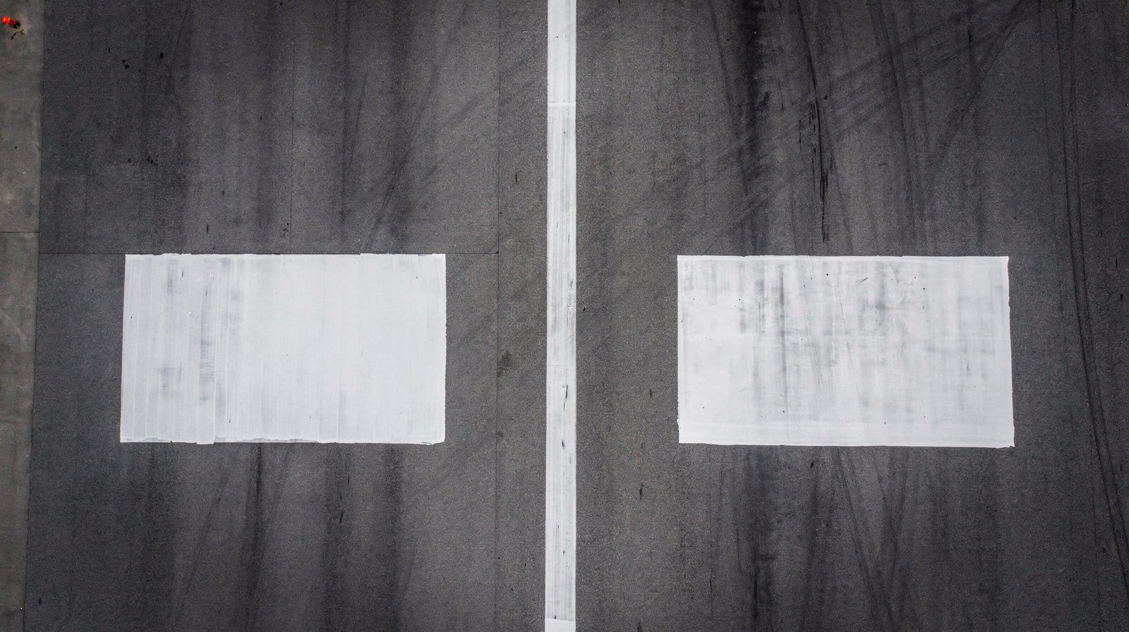
Airfield pavement markings are standardized visual aids applied to runway, taxiway, and apron pavement surfaces that transmit essential navigational information to pilots during all phases of ground and flight operations. Unlike signage or lighting, pavement markings are passive visual aids that rely on contrast against the pavement surface and retroreflective properties to remain visible both day and night. Their condition directly impacts runway safety, taxiway guidance accuracy, and the prevention of runway incursions.
The fundamental purpose of airfield pavement markings is to provide pilots with continuous visual guidance that supplements or replaces electronic navigation aids during surface movement. ICAO Annex 14 Volume I, Aerodromes, Chapter 5 (Visual Aids for Navigation), Section 5.2 (Markings), establishes the Standards and Recommended Practices (SARPs) that all 193 ICAO member states must implement. These SARPs cover marking color, dimensions, placement, and application conditions for all aerodrome pavement surface categories.
Runway markings are white per ICAO Annex 14 and FAA standards. The white color was selected for maximum contrast against the dark gray or black tones of asphalt pavement during daytime operations. Taxiway markings, by contrast, are yellow, a deliberate color differentiation that immediately signals to pilots whether they are on a runway (white markings) or a taxiway/apron (yellow markings). Apron markings may be white or yellow depending on function. Mandatory instruction markings, such as runway holding position markings, use a red background with white inscriptions where surface-painted signs are employed.
ICAO Annex 14 specifies that markings must be applied to paved runways, taxiways, and aprons where the surface is intended for aircraft operations. The standard requires that markings be maintained in a clean and visible condition at all times. Deteriorated, faded, or obscured markings that reduce visibility below acceptable levels constitute a non-compliance finding under aerodrome certification regimes including 14 CFR Part 139 (FAA airport certification) and EU Regulation 139/2014.
The FAA Advisory Circular AC 150/5340-1M (consolidated with Change 1, December 2020) is the primary FAA reference document for marking standards. This AC cancels the previous AC 150/5340-1L and is mandatory for projects funded under the Airport Improvement Program (AIP) and Passenger Facility Charge (PFC) programs. It also provides one acceptable means of compliance with Part 139 certification requirements. The AC contains full-scale AutoCAD-based figures showing precise dimensions, spacing, and positioning for every marking type along with color-coded instructional boxes, green for painting precautions, red for safety initiatives, and gray for general remarks.
Marking Types
Runway Markings
Runway markings are categorized by the type of runway approach procedure: visual runways, non-precision instrument runways, and precision instrument runways. Each category has progressively more marking elements. Per the FAA Aeronautical Information Manual (AIM) Chapter 2, Section 3, the marking elements required for each runway category are as follows:
| Marking Element | Visual Runway | Non-Precision Instrument | Precision Instrument |
|---|---|---|---|
| Designation | X | X | X |
| Centerline | X | X | X |
| Threshold | X¹ | X | X |
| Aiming Point | X² | X | X |
| Touchdown Zone | X | ||
| Side Stripes | X |
¹ On runways used or intended to be used by international commercial transports.
² On runways 4,000 feet (1,200 m) or longer used by jet aircraft.
Runway designation markings display the runway number, the whole number nearest one-tenth the magnetic azimuth measured clockwise from magnetic north, divided by 10, and, where applicable, the associated letter (L, C, or R for left, center, or right parallel runways). The numerals and letters are painted in white and centered on the runway centerline per FAA AC 150/5340-1M paragraph 2.3.5, which introduced new centering guidelines in the 2019 revision.
Runway centerline markings consist of uniformly spaced white stripes and gaps. Per FAA standards, each stripe is 120 feet (36.6 m) long with 80-foot (24.4 m) gaps, producing a repeating pattern. The total width of each stripe is typically 12 to 18 inches (30 to 45 cm) for precision runways. The centerline marking provides alignment guidance for aircraft during takeoff and landing roll. On precision instrument runways, the centerline marking is extended to the full runway length.
Runway threshold markings identify the beginning of the runway available for landing. They consist of longitudinal white stripes disposed symmetrically about the runway centerline. The number of stripes varies with runway width: 4 stripes for 60 ft (18 m), 6 for 75 ft (23 m), 8 for 100 ft (30 m), 12 for 150 ft (45 m), and 16 for 200 ft (60 m) as specified in FAA TBL 2-3-2. A threshold bar, a white transverse stripe 10 feet (3 m) wide, extends across the full runway width at the threshold location.
Runway aiming point markings serve as a visual aiming reference for landing aircraft. Per FAA standards, these consist of two rectangular white stripes, each 150 feet (45.7 m) long and approximately 30 feet (9 m) wide, located on each side of the runway centerline. The aiming point is positioned approximately 1,000 feet (305 m) from the landing threshold on precision and non-precision instrument runways 4,000 feet or longer used by jet aircraft.
Runway touchdown zone markings provide distance information in 500-foot (150 m) increments along the landing zone. They consist of groups of one, two, and three rectangular white bars symmetrically arranged in pairs about the runway centerline. A single bar pair denotes the first 500-foot increment, two bar pairs are used for the 500-1000 ft increment, and three bar pairs for the 1000-1500 ft increment. For runways with touchdown zone markings on both ends, marking pairs that would extend within 900 feet (270 m) of the runway midpoint are omitted.
Runway side stripe markings delineate the edges of the runway surface and provide visual contrast between the runway and abutting terrain or shoulders. These are continuous white stripes, typically 12 to 36 inches (30 to 90 cm) wide, located along each side of the runway. They are required on precision instrument runways per ICAO Annex 14 and FAA standards. Runway shoulder markings, yellow stripes, may supplement side stripes to identify paved areas contiguous to the runway that are not intended for aircraft use.
Displaced threshold markings use white arrows along the centerline from the runway beginning to the displaced threshold, ending in arrowheads across the runway width before a white threshold bar. The area behind a displaced threshold is available for takeoffs in either direction and for landings from the opposite direction but not for landings approaching the displaced end.
Chevron markings (yellow) are used on blast pads, stopways, and Engineered Materials Arresting Systems (EMAS) to indicate pavement areas aligned with the runway that are unusable for landing, takeoff, or taxiing. Chevrons point in the direction of the runway.
Demarcation bars (yellow, 3 feet/1 m wide) delineate a runway with a displaced threshold from a preceding blast pad, stopway, or taxiway.
Taxiway Markings
Taxiway markings are universally yellow per both ICAO and FAA standards. The primary taxiway marking is the taxiway centerline marking, a single continuous yellow line 6 to 12 inches (15 to 30 cm) wide that provides continuous guidance along the designated taxi path. Ideally, the aircraft should be kept centered over this line during taxi, though being centered does not guarantee wingtip clearance with other aircraft or objects.
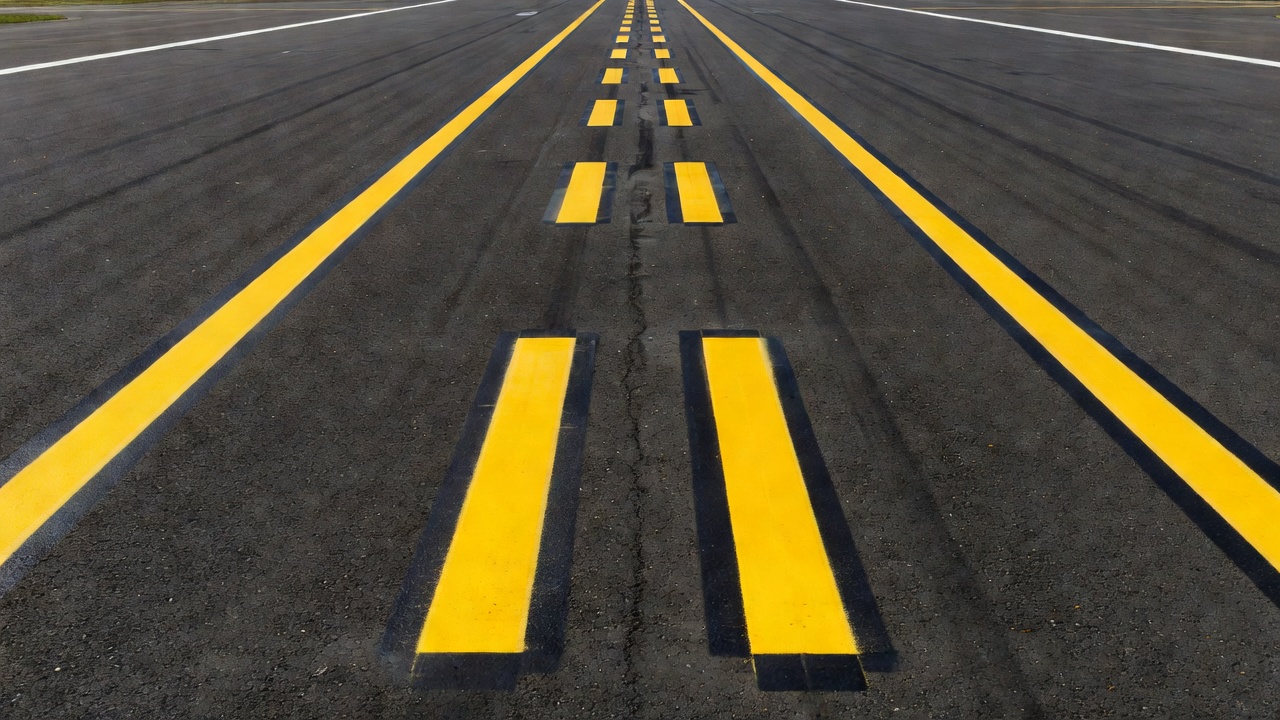
Enhanced taxiway centerline markings consist of the normal centerline plus parallel yellow dashes on each side for a maximum of 150 feet (45 m) before a runway holding position marking. The enhancement alerts pilots that they are approaching a runway hold point and should prepare to stop unless cleared by ATC. FAA AC 150/5340-1M requires conformance to Figure D-6 for enhanced taxiway centerline markings collocated with on-center surface painted holding position signs.
Taxiway edge markings define the edge of the usable taxiway surface. Continuous taxiway edge markings (double solid yellow lines, each at least 6 inches wide, spaced 6 inches apart) indicate pavement not intended for aircraft use adjacent to the taxiway, typically shoulders. Dashed taxiway edge markings (broken double yellow lines, 15-foot segments with 25-foot gaps, each line 6 inches wide spaced 6 inches apart) indicate adjoining pavement, such as an apron, that is available for aircraft use.
Runway holding position markings are the most critical taxiway markings. They consist of four yellow lines, two solid and two dashed, extending across the full width of the taxiway or runway. The solid lines are always on the side where the aircraft must hold. The line pattern, from the taxiway side, is: dashed, solid, solid, dashed. Per ICAO Annex 14, the runway-holding position marking is required at all taxiway/runway intersections. FAA AC 150/5340-1M distinguishes between Pattern A (the standard four-line pattern) and Pattern B (the approach/departure holding position marking with enhanced visual cues). As of Change 1 (December 2020), Pattern B replaced Pattern A for protecting approach/departure areas, accompanied by new vertical signage.
ILS holding position markings protect the Instrument Landing System critical and sensitive areas. These markings are similar to runway holding position markings but are located where taxiways intersect ILS critical areas rather than runways. Intermediate holding position markings (single dashed yellow line across the taxiway) are used at taxiway/taxiway intersections where ATC requires aircraft to hold short of the intersecting taxiway.
Surface painted taxiway direction signs have a yellow background with black inscriptions. They are located adjacent to the centerline, left side for left turns, right side for right turns. Surface painted location signs have a black background with yellow inscriptions, placed on the right side of the centerline to confirm the designation of the taxiway on which the aircraft is positioned.
Geographic position markings (GPMs) are circular markings with an outer black ring, a white ring, and a pink center, designated with numbers or alphanumeric codes. They are installed along low-visibility taxi routes designated in the airport’s Surface Movement Guidance Control System (SMGCS) plan. On dark pavements, the white and black rings are reversed. GPMs are used when RVR is below 1,200 feet (360 m) and are positioned to the left of the taxiway centerline in the direction of taxi.
Taxi shoulder markings (yellow) are used where conditions such as islands or taxiway curves may cause confusion as to which side of the edge stripe is for aircraft use, indicating the paved shoulder is unusable.
Apron Markings
Apron markings manage aircraft parking positions, ground vehicle movements, and pedestrian access on aprons. These include aircraft stand markings (lead-in lines, turn-in points, stop positions, and lead-out lines) typically painted in yellow or white depending on national standards. Apron control markings use numbered circles or triangles, circular shapes between terminals or triangular shapes for specific parking configurations. FAA AC 150/5340-1M Chapter 4 provides extensive guidance on sequential circular-shaped markings and triangular-shaped apron control marking dimensions.
Non-movement area boundary markings separate areas under ATC control (movement areas) from those where aircraft and vehicles operate at the pilot’s or driver’s own responsibility. These consist of two parallel yellow lines, one solid and one dashed, extending across the taxiway or apron entrance. The solid line is on the movement area side, and the dashed line is on the non-movement area side.
Mandatory Instruction Markings
Mandatory instruction markings supplement vertical mandatory instruction signs. They include surface-painted RUNWAY HOLDING POSITION signs (white inscription on a red background) located immediately before runway holding position markings. Per FAA AC 150/5340-1M, the enhanced taxiway centerline marking pattern collinear with on-center surface painted holding position signs follows ICAO Annex 14 criteria as depicted in Figure D-6. Mandatory instruction markings require pilots to obtain ATC clearance before proceeding beyond the marking.
No-entry markings (white on red) prohibit entry into a specific area. Road-holding position markings at road entrances to runways consist of a pattern of lines similar to runway holding position markings but applied to the roadway surface. Per ICAO Annex 14 Section 5.2.15, a road-holding position marking shall be provided at all road entrances to a runway.
Marking Materials
The selection of pavement marking material has a direct impact on marking longevity, retroreflectivity retention, friction characteristics, maintenance frequency, and lifecycle cost. The major material categories used in airfield applications are described below.
Waterborne Paint
Waterborne paint (also called waterborne or water-based acrylic paint) is the most commonly used airfield marking material, particularly for routine repainting cycles. It consists of an acrylic resin emulsion, pigments (titanium dioxide for white, lead-free yellow pigments for yellow), water as the solvent, and additives for drying control and durability. Waterborne paint is applied at a wet film thickness typically ranging from 15 to 20 mils (0.38 to 0.51 mm), drying by water evaporation and coalescence of the acrylic resin particles.
Advantages include low VOC (volatile organic compound) content, ease of application with standard striping equipment, rapid drying time (typically 10-30 minutes depending on temperature and humidity), and relatively low material cost. Disadvantages include limited service life, typically 1 to 2 years under airfield traffic conditions, and susceptibility to wear in high-traffic areas such as runway touchdown zones and taxiway intersections.
Solvent-Based Paint
Solvent-based paints (also called alkyd or epoxy ester paints) use organic solvents as the carrier rather than water. These paints generally offer better adhesion to asphalt surfaces, faster drying in cold or humid conditions, and improved durability compared to waterborne paints. However, they have higher VOC content and are subject to increasing environmental restrictions under air quality regulations. Solvent-based paints have largely been replaced by waterborne paints at most airfields due to environmental compliance requirements.
Thermoplastic
Thermoplastic marking material is a homogeneous hot-melt mixture of hydrocarbon or alkyd resin, pigment, glass beads, filler materials (calcium carbonate or silica), and plasticizers. Thermoplastic is supplied in solid block or granular form and must be heated to 400-450 °F (204-232 °C) in a specialized application kettle before application. Once heated to a liquid state, the material is applied by extrusion or spray at a thickness ranging from 90 to 120 mils (2.3 to 3.0 mm), significantly thicker than paint.
Thermoplastic cures by cooling (heat release), reverting to a solid state upon reaching ambient temperature. The cured marking has a raised profile that provides good durability under tire abrasion. Service life ranges from 3 to 5 years under favorable conditions, making it significantly more durable than paint.
Disadvantages include sensitivity to temperature during application (requires ambient temperature of 50 °F/10 °C and rising with no moisture for 24 hours), susceptibility to freeze-thaw cracking in cold climates, vulnerability to snowplow blade damage because the raised profile can be sheared off, poor performance on concrete unless a primer is applied, and the risk of overheating the material in the kettle (causing darkening and reduced retroreflectivity). FAA AC 150/5340-1M specifically prohibits preformed thermoplastic markings on runways due to significant reduction in pavement friction compared to bare pavement (Paragraph 1.3.2, red safety box). The FAA expects airports certified under Part 139 to correct existing preformed thermoplastic runway markings within one year of the AC’s effective date.
Preformed thermoplastic (also called preformed plastic tape or cold-applied thermoplastic) is manufactured in sheets or shapes with the marking pattern pre-formed. It is placed on the pavement surface and heated with a handheld propane torch to bond the material to the pavement. Preformed thermoplastics are commonly used for symbols, arrows, and lettering where precise pattern control is needed.
Methyl Methacrylate (MMA)
Methyl Methacrylate (MMA) is a two-component cold-applied marking system that cures through a chemical reaction between the resin base and a catalyst. MMA is mixed at ratios typically of 1:1, 98:2, or 4:1 (resin to catalyst) depending on the manufacturer and desired cure speed. The material forms a strong chemical bond with both asphalt and concrete surfaces without requiring a primer.
MMA offers exceptional durability, service life up to 10 years, even under extreme conditions including frequent snowplow impacts, studded tire traffic, and chemical exposure from deicing fluids. MMA cures in 15 to 30 minutes, minimizing airfield closure time during application. It can be applied at lower temperatures than thermoplastic, even near freezing conditions, by adjusting the catalyst concentration to control cure speed. MMA has excellent color retention, high retroreflectivity when properly embedded with glass beads, and resistance to freeze-thaw damage and UV degradation.
The primary disadvantage of MMA is higher material cost compared to paint or thermoplastic. However, the extended service life and reduced maintenance frequency often produce favorable lifecycle cost comparisons for high-traffic airfield applications.
Polyurea
Polyurea is a plural-component spray-applied marking material that cures rapidly through a chemical reaction between an isocyanate component and a resin blend component. Polyurea markings offer extreme durability, excellent flexibility (resistance to cracking), high chemical resistance, and rapid cure times (often less than 60 seconds). The FAA Airport Technology Research and Development Branch has conducted studies on polyurea paint marking materials, evaluating their performance as alternatives to standard waterborne, epoxy, methacrylate, and solvent-based markings that require frequent repainting.
Polyurea is particularly effective in demanding airfield environments where markings must endure jet fuel spills, hydraulic fluid exposure, deicing chemical attack, and heavy aircraft tire loads. The material can be formulated to accommodate glass bead embedment for retroreflectivity. However, specialized plural-component spray equipment is required, and the rapid cure time demands skilled application to avoid surface defects.
| Material | Service Life | Retroreflectivity Retention | Friction | Application Temp | Cost |
|---|---|---|---|---|---|
| Waterborne Paint | 1-2 years | Low to Medium | Good | 50-100 °F (10-38 °C) | Low |
| Solvent Paint | 1-3 years | Medium | Good | 40-100 °F (4-38 °C) | Low-Medium |
| Thermoplastic | 3-5 years | Medium-High | Reduced (raised profile) | 50 °F+ (10 °C+) | Medium |
| MMA | 5-10 years | High | Good | Below freezing to hot | Medium-High |
| Polyurea | 5-10+ years | High | Good | 40-120 °F (4-49 °C) | High |
Glass Beads and Retroreflectivity
Retroreflectivity is the optical property of a marking that reflects light from an aircraft’s landing lights or taxi lights back toward the pilot’s eyes, making the marking visible at night. This property is achieved through the incorporation of glass beads (also called glass spheres or reflective media) into the marking material.
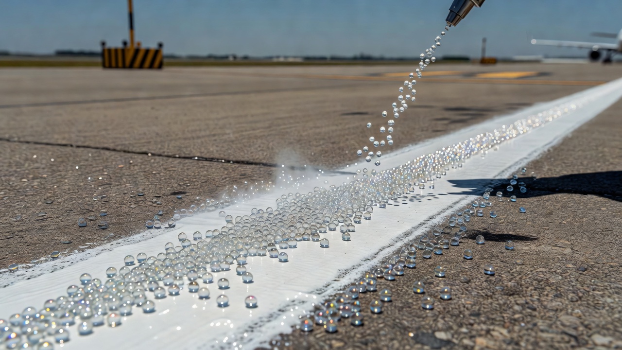
Glass beads used in airfield pavement markings are manufactured from soda-lime glass with a refractive index typically between 1.50 and 1.55. The beads are available in standard sizes ranging from 100 mesh (150 microns) to 16 mesh (1,180 microns) per ASTM D1155 standards. The beads must have a minimum roundness of 70-80% (depending on specification) and be free from contaminants. They are either mixed into the marking material during manufacturing (intermix beads) or applied to the wet marking surface immediately after application (drop-on beads).
The mechanism of retroreflectivity works through three optical phenomena: refraction of light entering the bead, reflection off the back surface of the bead (the bead-pavement or bead-binder interface), and refraction of the reflected light back toward the source. For optimal retroreflectivity, the bead must be embedded to approximately 50-60% of its diameter in the marking binder. Over-embedding (too deep) reduces retroreflectivity because the light-reflecting back surface is covered, under-embedding (too shallow) allows beads to dislodge prematurely under traffic.
Retroreflectivity is measured in units of millicandelas per square meter per lux (mcd/m²/lux) using standardized 30-meter geometry per ASTM E1710. This geometry simulates the viewing angle of a pilot looking at a pavement marking from an aircraft at typical taxi or landing distances. Mobile retroreflectometers such as the Laserlux G7 (RoadVista) and RetroTek-D (RetroTek USA) can scan full pavement widths in a single pass at normal vehicle speeds, producing continuous retroreflectivity measurements across the entire marking system.
ICAO Annex 14 recommends that marking retroreflectivity be maintained at levels adequate for night operations, though it does not prescribe specific minimum values. FAA AC 150/5340-1M requires that glass beads be incorporated into all pavement markings. The FAA’s Airport Cooperative Research Program (ACRP) has conducted extensive research on pavement marking retroreflectivity through reports such as ACRP Research Report 247: “Airfield Pavement Markings, Effective Techniques for Maintaining and Restoring Retroreflectivity.”
Marking Condition Assessment
Assessment of pavement marking condition involves four primary parameters: color, contrast, physical integrity, and night visibility (retroreflectivity).
Color assessment evaluates whether the marking material has retained its specified color, white for runways, yellow for taxiways, without significant fading or discoloration. Color fading is caused by UV radiation, chemical attack, and tire abrasion. For white markings, a shift toward gray indicates pigment loss. For yellow markings, fading toward pale yellow or cream indicates degradation. Color is evaluated visually and can be quantified using a colorimeter measuring CIE Lab color space values or using spectral reflectance measurements per ASTM E1349.
Contrast assessment measures the visual distinction between the marking and the surrounding pavement. High contrast is essential for daylight visibility. Contrast is influenced by marking color saturation, pavement surface color (new asphalt is very dark, providing high contrast, weathered asphalt becomes lighter, reducing contrast), and contamination from rubber deposits, dirt, or oil stains. Rubber tire deposits accumulate heavily in runway touchdown zones, significantly reducing marking contrast.
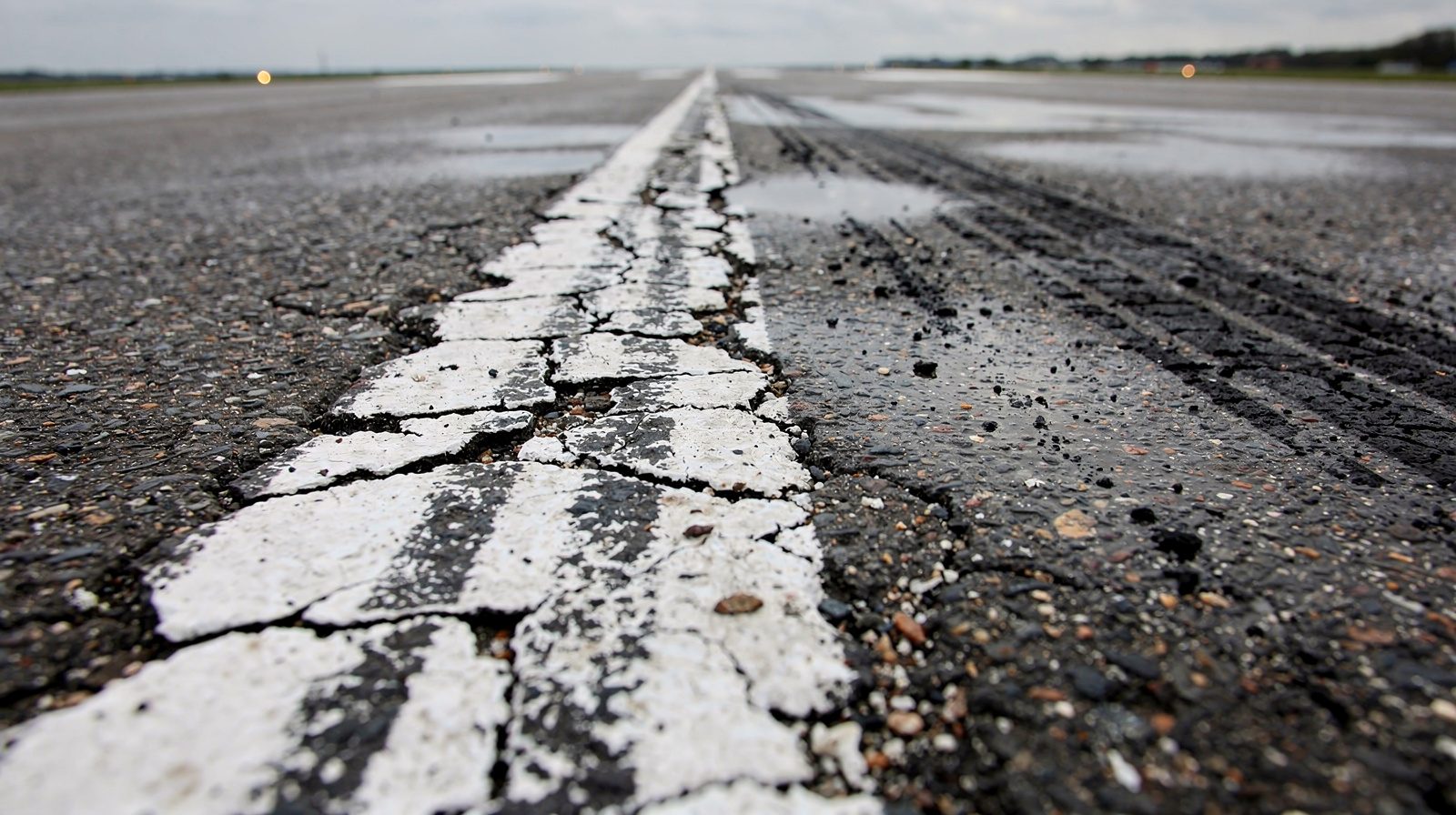
Physical integrity assessment examines the marking for cracking, peeling, delamination, raveling, potholing, and edge deterioration. Cracking occurs when the marking material cannot accommodate thermal expansion and contraction of the pavement, particularly problematic with thermoplastic. Peeling and delamination happen when the marking loses adhesion to the pavement, often due to moisture trapped beneath the marking or inadequate surface preparation. Raveling is the loss of aggregate or filler from the marking surface. Edge wear results from tire abrasion along marking edges.
Night visibility (retroreflectivity) assessment quantifies the marking’s ability to reflect light back to the pilot. Retroreflectivity is measured in mcd/m²/lux using portable or mobile retroreflectometers as described in the previous section.
Marking Inspection Methods
Traditional airfield marking inspection relies on daily visual inspection conducted by airport operations personnel as part of the self-inspection program required under 14 CFR Part 139. Inspectors drive the full runway and taxiway network, visually assessing marking condition at normal vehicle speeds. Anomalies are documented with digital cameras, GPS location tagging, and written descriptions. This method is subjective, different inspectors may rate the same marking differently, and cannot capture quantitative retroreflectivity data.
Mobile retroreflectometer surveys provide objective, quantitative measurement of marking retroreflectivity. A mobile retroreflectometer mounted on a vehicle scans markings at speeds up to 50 mph (80 km/h) using a laser source and photodetector array. The instrument produces a continuous retroreflectivity profile along the marking, identifying sections below acceptable thresholds. Mobile surveys are typically conducted annually or semi-annually.
Walk-down inspections involve personnel walking the full length of critical markings (especially runway centerlines, threshold markings, and holding positions) at close range to evaluate physical integrity, cracking, delamination, and edge wear. These inspections are labor-intensive but provide the most detailed physical assessment data.
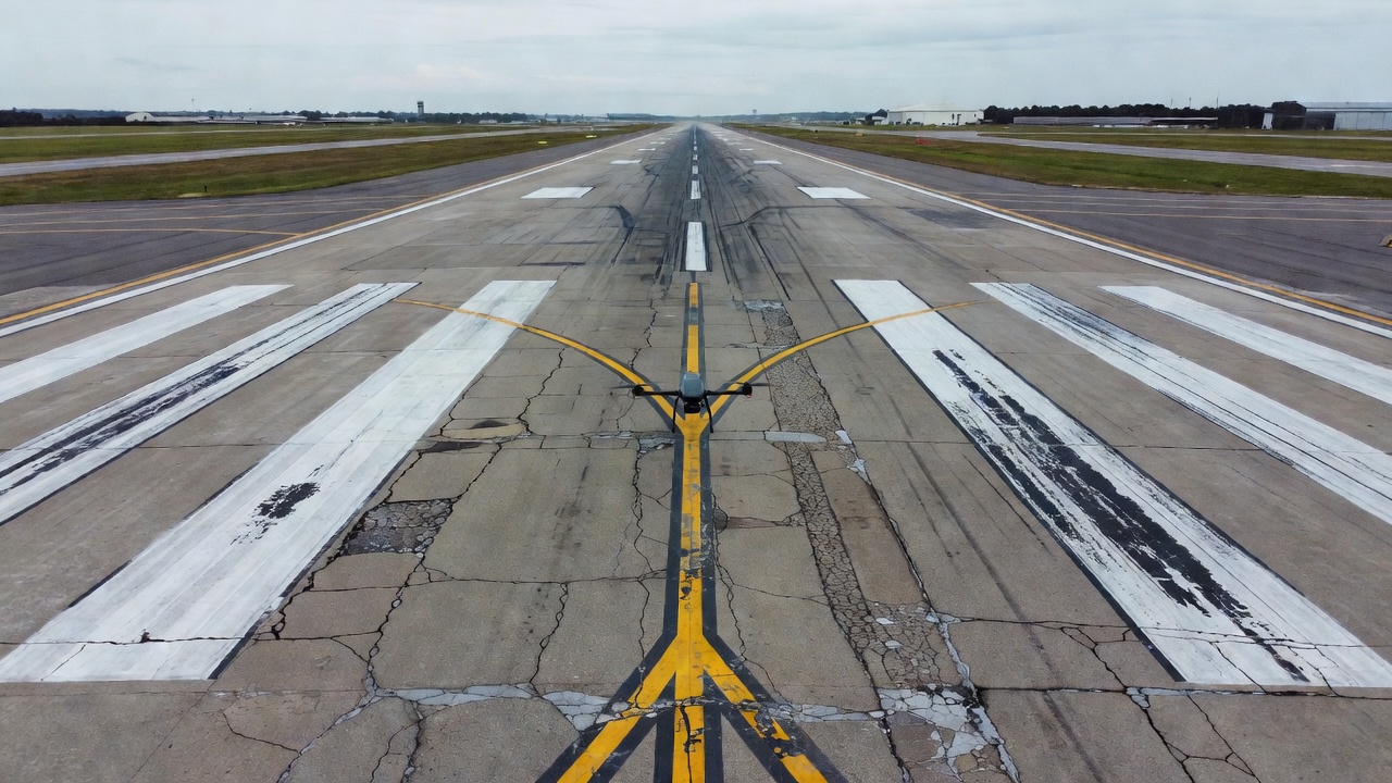
Photogrammetric and AI-based inspection using drone-acquired imagery represents the emerging state of the art. A UAV (unmanned aerial vehicle) equipped with a high-resolution camera (20+ megapixel, typically with a global shutter) flies a programmed grid pattern over the runway or taxiway at altitudes of 50-100 ft (15-30 m), capturing overlapping images at 1-2 cm ground sampling distance (GSD). Images are processed using Structure from Motion (SfM) photogrammetry to produce a georeferenced orthomosaic and digital surface model (DSM) of the entire pavement area.
Recent research published in Sensors (2026) by Krestenitis et al., “Digitalization and Automation of Runway Inspection Using Unmanned Aerial Vehicles”, validated an end-to-end framework integrating UAV data collection, deep learning-based pixel-level semantic segmentation of surface defects including marking deterioration, and GIS-based spatial aggregation to generate a georeferenced Pavement Condition Index (PCI)-inspired assessment. The framework was validated at Zadar Airport, Croatia, where the full runway was surveyed and multiple defect categories were automatically identified and mapped at pixel resolution.
Deep learning semantic segmentation models, typically based on U-Net, DeepLabV3+, or SegFormer architectures, are trained to classify each pixel in the orthomosaic as “marking in good condition,” “marking deteriorated,” “crack through marking,” “marking covered,” or “pavement surface.” These models achieve pixel-level accuracy and can quantify the percentage of marking area that meets condition standards. The GIS-based aggregation module then calculates defect density within predefined sampling units (typically 5,000 ft² per ASTM D5340-20) and computes a condition index for each unit.
Marking Maintenance and Remarking
Marking maintenance encompasses activities to preserve marking visibility, retroreflectivity, and physical integrity between repainting cycles. Cleaning is the most basic maintenance activity, rubber deposits in the touchdown zone are removed using high-pressure water blasting or chemical cleaning to restore marking contrast and reveal underlying retroreflectivity. Rubber removal is typically scheduled based on friction testing results and visual assessment, with frequency ranging from monthly at high-traffic airports to annually at lower-traffic facilities.
Spot repair addresses localized marking damage such as a delaminated section of centerline marking or a peeled section of holding position marking. The damaged material must be completely removed before reapplication to ensure proper adhesion. Marking removal methods include water blasting (ultra-high pressure water at 30,000+ psi), shot blasting (steel shot propelled at the pavement), sand blasting, chemical removal, and mechanical grinding (milling). FAA AC 150/5340-1M specifies water blasting and shot blasting as preferred methods, with sand blasting, chemical removal, or mechanical grinding as acceptable alternatives.
Remarking (full remarking or repainting) renews the entire marking system. The interval between remarking depends on marking material type, traffic volume, climate, and observed condition. Typical cycles are:
| Material | Remarking Cycle |
|---|---|
| Waterborne paint | 1-2 years |
| Solvent paint | 2-3 years |
| Thermoplastic (spray/extruded) | 3-5 years |
| MMA | 5-10 years |
| Polyurea | 5-10 years |
The surface preparation process before remarking is critical. Old marking material must be removed or overcoated (if compatible). The pavement surface must be clean, dry, and at appropriate temperature. For thermoplastic and MMA, the ambient and surface temperatures must be within the material manufacturer’s specified range. FAA AC 150/5340-1M emphasizes training of personnel performing marking application as a key factor in achieving desired marking quality and longevity.
Friction considerations are paramount. Per FAA AC 150/5340-1M Paragraph 1.3.2 (red safety box), preformed thermoplastic markings must not be applied on runways because their raised profile significantly reduces pavement friction compared to bare pavement. All runway markings should provide friction characteristics comparable to the surrounding pavement surface.
Marking in Drone-Based Inspection
Drone-based inspection is transforming airfield pavement marking condition assessment by enabling rapid, comprehensive, and quantitative evaluation of marking systems across the entire aerodrome. A single drone flight can cover a 10,000-ft (3,048 m) runway in less than 30 minutes, capturing imagery at sub-centimeter resolution that reveals marking deterioration invisible from a ground vehicle.
The workflow for drone-based marking inspection comprises five stages. Mission planning defines the flight area, altitude (typically 60-120 ft/20-40 m for marking inspection), overlap (80% forward, 70% side overlap for photogrammetric quality), and ground sampling distance (0.5-1.5 cm/pixel). Flight paths are programmed to maintain consistent lighting conditions and avoid shadows. Data acquisition uses a multi-rotor UAV with RTK (Real-Time Kinematic) GPS positioning for centimeter-level georeferencing without ground control points. Photogrammetric processing stitches individual images into a seamless orthomosaic and digital surface model using SfM software. The orthomosaic is georeferenced to the local coordinate system and typically exported at 1-2 cm GSD.
AI-based marking condition analysis applies semantic segmentation deep learning models to classify each pixel in the orthomosaic. The model identifies marking boundaries, quantifies percentage deterioration within each marking element, detects missing sections, and measures marking width against specification. Neural network architectures such as U-Net with EfficientNet backbones or transformer-based models (SegFormer, Mask2Former) achieve intersection-over-union (IoU) scores of 0.85-0.95 for marking detection.
Condition reporting outputs a georeferenced marking condition map with each marking element color-coded by condition rating (excellent, good, fair, poor, failed). Defect density percentages are calculated per ASTM-based sampling units. The report automatically identifies marking elements below minimum condition thresholds and prioritizes them for maintenance action.
The FAA and ICAO have not yet issued formal guidance accepting drone-based marking inspection as a direct replacement for visual inspection. However, the technology is increasingly used as a supplementary tool that provides quantitative, repeatable, and auditable condition data.
FOD from Marking Deterioration
Foreign Object Debris (FOD) from deteriorated pavement markings is a recognized safety hazard. As markings degrade, pieces of marking material can detach from the pavement surface and become FOD. This is particularly problematic with thermoplastic and MMA markings that have delaminated, cracked, or been damaged by snowplow blades. Loose sections of preformed thermoplastic marking tape can peel up and fragment, creating debris that an aircraft engine can ingest or that can damage landing gear components.
Per the FAA FOD Program, FOD is defined as “any object, live or not, located in an inappropriate location in the airport environment that has the capacity to injure airport or air carrier personnel or damage aircraft.” Deteriorated marking material meets this definition. The FAA requires airport operators to conduct continuous FOD monitoring, and marking condition is a direct element of this program.
Thermoplastic and MMA markings that crack and delaminate are the highest FOD risk among marking materials. Waterborne paint, which wears gradually through abrasion rather than fracturing, presents minimal FOD risk. FOD prevention measures for pavement markings include regular visual inspection for loose, peeled, or delaminated marking sections, prompt removal of any loose marking material found during daily inspections, priority repair of delaminated sections before they become FOD, use of marking materials with good adhesion characteristics, proper surface preparation before marking application, prohibition of preformed thermoplastic on runways due to friction reduction AND FOD generation potential, and immediate sweep of any area where marking removal or repair has been performed.
Standards Summary
The primary standards governing airfield pavement markings are:
ICAO Annex 14 Volume I, Aerodromes, 8th Edition (July 2018), incorporating Amendments up to 18. Chapter 5, Visual Aids for Navigation, Section 5.2, Markings. This is the international standard document that all 193 ICAO member states must implement. It covers marking colors (white for runways, yellow for taxiways, red for mandatory instruction signs), dimensions, placement requirements, and recommended maintenance practices.
FAA Advisory Circular AC 150/5340-1M, Standards for Airport Markings (May 2019, with Change 1 effective December 2020). This is the primary U.S. standard document, cancelling AC 150/5340-1L. It is mandatory for AIP and PFC-funded projects and provides means of compliance with 14 CFR Part 139. The AC includes detailed AutoCAD figures for all marking types plus color-coded instructional boxes.
FAA Advisory Circular AC 150/5340-18G, Standards for Airport Sign Systems (related to marking-signage integration).
14 CFR Part 139, Certification of Airports, which requires an airport certification manual, self-inspection program, and pavement maintenance program that includes marking condition.
ASTM D5340-20, Standard Test Method for Airport Pavement Condition Index Surveys, which defines the PCI methodology for quantifying pavement condition including marking-related distress.
EU Regulation 139/2014, which establishes common requirements for aerodrome certification in European Union member states.
ACRP Research Report 247, Airfield Pavement Markings: Effective Techniques for Maintaining and Restoring Retroreflectivity, which provides comprehensive guidance on managing marking retroreflectivity throughout the marking lifecycle.
The relationship between these standards is hierarchical: ICAO Annex 14 establishes international SARPs, national authorities (FAA, EASA, CASA) adopt these into national regulations, and advisory documents provide implementation details. Compliance is verified through aerodrome certification audits and regular safety inspections.
Frequently Asked Questions
- What is the difference between precision and non-precision instrument runway markings?
- Precision instrument runway markings include all elements of non-precision markings (designation, centerline, threshold, aiming point) plus touchdown zone markings and side stripes. Per ICAO Annex 14 and FAA standards, precision runways also require runway side stripe markings to delineate pavement edges and touchdown zone markers in 500-foot increments. Non-precision instrument runways have aiming point markings only on runways 4,000 feet or longer used by jet aircraft. Visual runways have the fewest markings, designation, centerline, and threshold (the latter only when used by international commercial transports).
- How often should airfield pavement markings be inspected?
- Pavement markings are visually inspected during daily airfield self-inspections required under 14 CFR Part 139 for certificated airports. More detailed condition assessments, including retroreflectivity measurement, color evaluation, and physical integrity checks, are performed on a recurring schedule based on marking material type, traffic volume, and environmental exposure. The FAA recommends comprehensive marking evaluations at least annually, with mobile retroreflectometer surveys conducted at intervals determined by pavement marking material and expected service life.
- What causes pavement marking deterioration on airfields?
- Pavement marking deterioration results from a combination of factors: aircraft tire abrasion (especially in touchdown zones and along taxiway centerlines), UV radiation exposure from sunlight, chemical attack from jet fuel and deicing fluids, thermal cycling and freeze-thaw action, snowplow blade impact, water infiltration causing delamination from the pavement surface, and mechanical wear from ground support equipment vehicles. Rubber tire deposits also accumulate on runway markings in touchdown zones, reducing contrast and retroreflectivity.
- What are the retroreflectivity requirements for airfield pavement markings?
- ICAO Annex 14 recommends that runway and taxiway markings maintain adequate retroreflectivity for night operations. FAA AC 150/5340-1M specifies that glass beads shall be incorporated into pavement markings to provide retroreflectivity. While specific minimum retroreflectivity values for airfields are less prescriptive than highway standards, FAA guidance requires that markings be maintained to provide sufficient night visibility. Mobile retroreflectometers measure marking retroreflectivity in units of mcd/m²/lux using 30-meter geometry.
This is a reference entry. TarmacView provides drone inspection services and doesn't sell the equipment or materials described in this glossary.