Reconstruction
Reconstruction is the complete removal and replacement of a pavement structure from subgrade up, performed when the pavement has reached terminal condition and ...
25 min read
Pavement
Airport infrastructure
+3
Reconstruction is the complete removal and replacement of a pavement structure from subgrade up, performed when the pavement has reached terminal condition and rehabilitation is no longer cost-effective. Covers full-depth removal, subgrade improvement, new base and surface construction, and the decision point between rehabilitation and reconstruction.
Pavement Reconstruction is the complete removal and replacement of the entire pavement structure — including surface course, base course, subbase, and, when necessary, the subgrade — to restore the pavement to a condition equivalent to new construction. Per FAA Advisory Circular 150/5320-6G (Airport Pavement Design and Evaluation) , reconstruction is the most extensive pavement intervention, performed when a pavement has reached its terminal condition and all other rehabilitation strategies — overlays, full-depth repairs, or recycling — are no longer technically feasible or economically justified.
The International Civil Aviation Organization (ICAO) addresses pavement reconstruction through Annex 14 — Aerodromes, Volume I (Aerodrome Design and Operations) and the Aerodrome Design Manual (Doc 9157, Part 3 — Pavements) . ICAO requires that aerodrome pavements be maintained in a condition that ensures the safety of aircraft operations. When pavements deteriorate beyond the point where maintenance and rehabilitation can restore adequate structural capacity, reconstruction becomes the only option to comply with ICAO’s requirement for pavements to support the design aircraft without inducing structural damage to the aircraft or the pavement itself.
The decision to reconstruct a pavement represents a major capital investment that typically costs 3 to 5 times more than rehabilitation on a per-unit-area basis. For airport pavements, reconstruction costs at large hub airports can range from $50 to $200 per square yard depending on pavement type, thickness, material costs, and site conditions. The total project cost must also account for operational impacts, phasing requirements, airfield ground lighting adjustments, navigational aid modifications, and the cost of maintaining airfield operations during construction.
The fundamental distinction between reconstruction and other pavement interventions lies in the extent of removal and replacement. Rehabilitation leaves all or part of the existing pavement structure in place and extends its service life. Reconstruction removes everything and starts from the subgrade, effectively resetting the pavement’s service life to zero and providing the full original design life — typically 20 years minimum per FAA requirements, with the FAA’s Extended Airport Pavement Life program targeting 40 years for runways at large hub airports through improved materials, thicker designs, and enhanced quality control.
FAA AC 150/5320-6G provides the authoritative regulatory framework for distinguishing between rehabilitation and reconstruction of airport pavements. Section 4.3 defines Rehabilitation as “the replacement of a portion of the pavement structural layers. It is generally more cost effective to rehabilitate a pavement early in its life before extensive structural damage has occurred.” Section 4.4 defines Reconstruction as the complete removal and replacement of the pavement structure, which is undertaken when the pavement is no longer viable for rehabilitation.
The FAA’s Pavement Management Program (PMP) guidance in AC 150/5380-7B illustrates the decision framework through the Pavement Condition Life Cycle curve (Figure 1 of the AC). This curve shows that pavement deteriorates slowly for the majority of its life (the “good” condition zone), then reaches a critical condition at which deterioration accelerates rapidly — the “fair” to “poor” transition zone. The ideal time for major rehabilitation is just as the pavement reaches this critical condition point. If the pavement is allowed to deteriorate past this point into the “poor” or “failed” condition (typically PCI below 40-55 depending on the agency’s threshold), the deterioration accelerates and the pavement enters a state where rehabilitation can no longer restore adequate structural performance, making reconstruction the only viable option.
The Pavement Condition Index (PCI) methodology per ASTM D5340 (Standard Test Method for Airport Pavement Condition Index Surveys) provides the quantitative basis for this decision. The PCI scale ranges from 0 (failed) to 100 (excellent). Pavements with a PCI above 70 are typically candidates for preventive maintenance such as crack sealing, seal coating, or thin overlays. Pavements with a PCI between 40 and 70 are candidates for structural rehabilitation such as overlays (typically 75-150 mm of hot mix asphalt) or full-depth repairs of localized distressed areas. Pavements with a PCI below 40, particularly those exhibiting structural distress such as alligator cracking, pumping, rutting deeper than 25 mm, or edge cracking, are typically beyond the point where rehabilitation is cost-effective and require reconstruction.
The FHWA (Federal Highway Administration) provides additional guidance through its Pavement Performance Measures and Forecasting study (FHWA-HRT-17-095), which defines a dual rating system based on Remaining Functional Life (RFP) and Remaining Structural Life (RSP) . Pavements with an RSP of less than 2 years (CS 1a — “Very Poor”) are categorized as requiring reconstruction under the five-level condition state (CS) system. The FHWA threshold values for reconstruction are typically an IRI (International Roughness Index) exceeding 2.7 m/km (172 inches/mile), alligator cracking exceeding 180 m² per 0.1 km (3,168 ft² per 0.1 mile), or rutting exceeding 12.5 mm (0.5 inch), depending on the specific distress type and pavement classification.
The key distinction between rehabilitation and reconstruction can be summarized through four criteria:
| Criterion | Rehabilitation | Reconstruction |
|---|---|---|
| Extent of removal | Partial (one or more lifts) | Full depth (surface to subgrade) |
| Subgrade treatment | Not typically addressed | Evaluated and improved if needed |
| Existing material reuse | Possible (mill and overlay, FDR) | Complete replacement (RAP may be recycled off-site) |
| Design life | 10-15 years (per FAA) | 20-40 years (per FAA) |
| Relative cost | 1x (baseline) | 3-5x rehabilitation cost |
| PCI range | 40-70 | Below 40 (terminal condition) |
The decision to recommend reconstruction over rehabilitation is based on a systematic evaluation of the pavement’s condition, structural capacity, and life-cycle cost. The evaluation process follows the framework established in FAA AC 150/5320-6G Chapter 4 (Pavement Maintenance, Rehabilitation and Reconstruction) and AC 150/5380-7B (Airport Pavement Management Program) .
The Pavement Condition Index (PCI) is the primary screening tool for determining whether reconstruction should be considered. Per ASTM D5340, the PCI is calculated from a visual survey that identifies the type, severity, and density of pavement distresses. The PCI is expressed as a numerical value from 0 to 100:
| PCI Range | Condition Rating | Recommended Action |
|---|---|---|
| 86-100 | Excellent | Routine maintenance only |
| 71-85 | Very Good | Preventive maintenance |
| 56-70 | Good | Minor rehabilitation |
| 41-55 | Fair | Major rehabilitation |
| 26-40 | Poor | Reconstruction or major rehabilitation |
| 11-25 | Very Poor | Reconstruction |
| 0-10 | Failed | Reconstruction |
Most airport operators establish a minimum acceptable PCI threshold — typically PCI 55-70 — below which pavements are scheduled for rehabilitation or reconstruction. When the PCI drops below 40, the pavement has typically entered a state of rapid deterioration where the cost of rehabilitation approaches the cost of reconstruction, making reconstruction the recommended option. The FAA’s PMP guidance (AC 150/5380-7B, Figure 1) illustrates that the cost of rehabilitating a pavement in “poor” condition is 4 to 5 times more expensive than preserving it in “good” condition, and by the time the pavement reaches “failed” condition, the cost of rehabilitation often exceeds the cost of reconstruction.
Structural failure is characterized by load-related distresses that indicate the pavement can no longer distribute aircraft or vehicle loads to the subgrade without excessive stress. The key distress types indicating structural failure include:
Alligator (Fatigue) Cracking — interconnected cracks forming a pattern of polygons resembling alligator skin, caused by repeated traffic loading exceeding the fatigue strength of the pavement. When alligator cracking covers more than 30-50% of the pavement surface at medium or high severity (ASTM D5340 severity levels), the pavement structure has structurally failed and reconstruction is typically required.
Rutting — permanent deformation in the wheel paths caused by consolidation or lateral movement of pavement layers. Rutting deeper than 25 mm (1 inch) that cannot be corrected by milling and overlay alone indicates structural failure of the base or subgrade. In airport pavements, rutting exceeding 12 mm (0.5 inch) at high severity is considered structurally significant per FAA guidance.
Pumping — the ejection of water and fine soil material from beneath the pavement through cracks or joints under traffic loading. Pumping indicates subgrade failure and erosion, and it typically requires reconstruction with improved drainage and subgrade stabilization.
Faulting — vertical displacement at concrete pavement joints caused by erosion of subbase material under the approach slab, combined with traffic loading. Faulting exceeding 6 mm (0.25 inch) at high severity indicates structural failure requiring reconstruction of rigid pavements.
Subgrade failure is the most fundamental cause requiring reconstruction because, without a competent subgrade, no pavement structure — regardless of thickness — can perform adequately. Subgrade failure is identified through:
Bearing Capacity Testing — using the California Bearing Ratio (CBR) test per ASTM D1883 or the Dynamic Cone Penetrometer (DCP) per ASTM D6951. Per FAA AC 150/5320-6G, subgrade soils with a CBR below 3 are generally unsuitable for airport pavement support without stabilization. Design subgrade CBR values for airport pavements typically range from 5 to 20, with higher CBR values required for pavements serving heavier aircraft.
Plate Load Tests — per AASHTO T 222 or ASTM D1195, measuring the modulus of subgrade reaction (k-value) for rigid pavement design or the resilient modulus (Mr) for flexible pavement design per the AASHTO Mechanistic-Empirical Pavement Design Guide.
Soil Classification — per AASHTO M 145 (Classification of Soils and Soil-Aggregate Mixtures for Highway Construction Purposes) or the Unified Soil Classification System (USCS) per ASTM D2487. Soils classified as A-6 (clayey), A-7 (highly plastic clayey), CH (high plasticity clay), or OH (organic clay) are susceptible to volume changes, frost heave, or strength loss when wet, and may require stabilization or removal and replacement during reconstruction.
Pavements that have received multiple overlay treatments over their service life often accumulate such excessive thickness that the surface elevation has risen above adjacent drainage structures, curbs, or shoulder grades. Each overlay raises the surface by 50-100 mm, and after 3-4 overlays (300-400 mm total elevation increase), the pavement profile may create drainage problems, sight distance issues, or load restrictions at bridges and structures. This condition — known as riding grade — necessitates reconstruction to restore the proper pavement elevation and profile.
When an airport or highway agency decides to change the pavement type (e.g., converting an existing flexible asphalt pavement to a rigid concrete pavement, or vice versa), reconstruction is required because the structural behavior and failure mechanisms of each pavement type are fundamentally different. An asphalt overlay on existing concrete (whitetopping reversed) or a concrete overlay on existing asphalt cannot simply be applied without addressing the entire structure. Partial reconstruction or full-depth reconstruction is typically required for type conversion.
Pavement reconstruction follows a systematic, phased process that is documented in the project plans and specifications. The FAA AC 150/5370-10H (Standard Specifications for Construction of Airports) provides the detailed material and construction standards for each stage.
Before reconstruction design begins, a comprehensive investigation of the existing pavement and subgrade is performed per FAA AC 150/5320-6G Chapter 2 (Soil Investigations and Evaluation) . The investigation includes:
Subsurface Exploration — boring and sampling at intervals specified in Table 2-1 of AC 150/5320-6G. For reconstruction projects, borings are typically spaced at 150-300 meters (500-1,000 feet) along runways and 75-150 meters (250-500 feet) on taxiways and aprons. Boring depths must extend below the proposed reconstruction depth, typically 1.5-3 meters (5-10 feet) below the existing pavement surface or until competent bearing material is encountered.
Material Sampling and Testing — obtaining samples of each pavement layer and the subgrade for laboratory testing. Tests include gradation (AASHTO T 27/T 11), Atterberg limits (AASHTO T 89/T 90), compaction characteristics (Modified Proctor per AASHTO T 180), CBR (ASTM D1883), and resilient modulus (AASHTO T 307). For rigid pavements, concrete cores are tested for compressive strength (ASTM C39) and flexural strength (ASTM C78).
Nondestructive Testing (NDT) — using Falling Weight Deflectometer (FWD) testing per ASTM D4694 to measure pavement deflection and back-calculate layer moduli. FAA AC 150/5320-6G Appendix C provides detailed guidance on NDT using FWD devices. FWD testing enables the engineer to identify weak areas, determine the structural capacity of existing layers, and design the reconstruction thickness efficiently. Ground Penetrating Radar (GPR) per FAA Appendix E is used to map layer thicknesses, identify utilities, and locate subsurface anomalies.
The new pavement structure is designed using FAARFIELD (FAA Rigid and Flexible Iterative Elastic Layer Design) for airport pavements, per FAA AC 150/5320-6G Chapter 3. FAARFIELD is a layered elastic analysis program that computes the required thickness of each pavement layer based on the design aircraft mix, annual departures, subgrade CBR or modulus, and material properties. For flexible pavements, the critical design criterion is the subgrade vertical compressive strain, which is related to the number of load repetitions to failure through the Federal Aviation Administration (FAA) failure criteria calibrated at the National Airport Pavement Test Facility (NAPTF) .
For highway pavements, design follows the AASHTO Guide for Design of Pavement Structures (1993) or the AASHTO Mechanistic-Empirical Pavement Design Guide (MEPDG) using the AASHTOWare Pavement ME Design software.
Key design parameters specified in AC 150/5320-6G include:
| Parameter | Flexible Pavement | Rigid Pavement |
|---|---|---|
| Design life | 20 years minimum (new) | 20 years minimum (new) |
| Subgrade modulus | CBR or Mr from testing | k-value from plate load test |
| Surface material | P-401 (HMA, Superpave) | P-501 (PCC, 4,000 psi min) |
| Base material | P-209 (aggregate) or P-304 (CTB) | P-304 (lean concrete) or P-306 |
| Minimum surface thickness | 100 mm (4 inches) | 150 mm (6 inches) |
| Minimum total thickness | Per FAARFIELD output | Per FAARFIELD output |
Existing pavement materials are removed to the design depth using either mechanical methods (cold planing, milling, ripping) or demolition methods (hydraulic breakers, wrecking balls for thick concrete). The FAA specifies removal under Item P-102 (Removal of Existing Pavement) of AC 150/5370-10H.
Cold Planing (P-101) — for asphalt pavements, cold planing machines with rotating drums and carbide cutting teeth remove the material in a controlled depth pass. Full-depth removal of asphalt pavements up to 300 mm (12 inches) can be performed in a single pass using large cold planers.
Ripping and Excavation — for concrete pavements, the existing concrete is typically broken using hydraulic hammers or resonant breakers mounted on excavators. The broken material is removed by excavators or loaders. Rubblization (breaking concrete into small pieces while leaving it in place as a base layer) is an alternative to removal for some reconstruction projects but is considered a rehabilitation technique, not reconstruction.
Reclaimed Asphalt Pavement (RAP) — all removed asphalt material is stockpiled for recycling. FAA AC 150/5320-6G and AC 150/5370-10H include specifications for RAP reuse in new pavement mixtures, with typical allowable RAP content of 20-30% in surface courses and up to 50% in base courses.
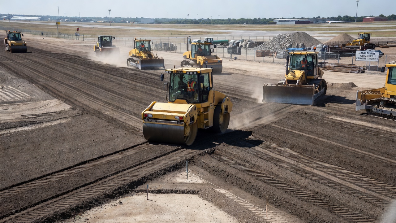
After existing pavement removal, the exposed subgrade is evaluated, graded, and compacted to meet the design requirements. FAA Item P-152 (Excavation, Subgrade, and Embankment) specifies compaction requirements:
Subgrade Compaction — the subgrade must be compacted to at least 95% of the maximum dry density per AASHTO T 180 (Modified Proctor) for the top 150 mm (6 inches) and to at least 90% for the remainder of the subgrade zone. Density verification is performed using nuclear density gauges per ASTM D6938 or sand cone tests per ASTM D1556.
Proof Rolling — after compaction, the subgrade is proof-rolled using a heavy pneumatic-tire roller to identify soft spots that require additional compaction or removal and replacement. Any areas that pump, rut, or deflect excessively under proof rolling must be excavated and replaced with approved fill material.
Drainage — subgrade drainage is critical for long-term pavement performance. The subgrade is graded to provide positive drainage, typically at cross-slopes of 1.5-2% for flexible pavements and 1.5% for rigid pavements per FAA AC 150/5320-6G. Underdrains may be required in cut sections or areas with high water tables.
Subgrade stabilization is one of the most critical aspects of pavement reconstruction because the subgrade provides the foundation for the entire pavement structure. Per FAA AC 150/5320-6G Section 2.4 (Subgrade Stabilization) , stabilization is required when the native soil has insufficient bearing capacity to support the pavement under the design traffic loading without excessive deformation.
Before selecting a stabilization method, the subgrade soil must be characterized through laboratory testing per FAA AC 150/5320-6G and AASHTO M 145:
| Soil Property | Test Method | Stabilization Threshold |
|---|---|---|
| CBR (soaked) | ASTM D1883 | < 5 requires stabilization |
| Plasticity Index (PI) | AASHTO T 90 | > 10-15 requires chemical treatment |
| Percent passing No. 200 sieve | AASHTO T 27 | > 25% indicates fine-grained soil |
| Organic content | ASTM D2974 | > 1% may inhibit cement hydration |
| Sulfate content | ASTM C1580 | > 0.3% requires special treatment |
| Swell potential | ASTM D4546 | > 2% free swell requires treatment |
Mechanical stabilization improves soil properties through physical processes without chemical additives:
Compaction — the simplest and most fundamental stabilization method. Soils are compacted at optimum moisture content (OMC) to achieve maximum dry density (MDD). The FAA requires compaction to at least 95% of MDD per Modified Proctor (AASHTO T 180) for the top subgrade zone.
Granular Overlay or Replacement — weak subgrade soils (CBR < 3) may be removed and replaced with select granular borrow material (typically A-1 or A-2 soils per AASHTO M 145) to a depth of 300-600 mm (12-24 inches). The replacement depth is designed to distribute stresses from the pavement to the underlying weaker soil at acceptable levels.
Geosynthetic Reinforcement — geotextiles (woven or nonwoven) and geogrids are placed at the subgrade-base interface to provide separation, filtration, and reinforcement. ASTM D6638 (Standard Test Method for Determining the Connection Strength Between Geogrid Reinforcement and Segmental Concrete Units) and ASTM D6241 (Tensile Strength of Geotextiles by the Wide-Width Strip Method) provide testing standards.
Chemical stabilization alters the soil’s physical and chemical properties to improve strength, reduce plasticity, and control volume change. The FAA treats stabilization in AC 150/5320-6G Chapter 2:
Cement Stabilization — Portland cement (ASTM C150, Type I or II) is mixed with the soil at dosages of 3-8% by dry weight of soil. Cement stabilization works best on granular soils (A-2, A-3, A-4) and produces rapid strength gain. The stabilized soil achieves unconfined compressive strengths of 1.0-3.0 MPa (150-450 psi) after 7 days of moist curing. FAA Item P-301 (Soil-Cement Base Course) provides construction specifications.
Lime Stabilization — hydrated lime (ASTM C977) or quicklime is used for clay soils (A-6, A-7, CH, MH) at dosages of 3-6% by dry weight. Lime reacts with clay minerals through cation exchange and pozzolanic reactions, reducing plasticity, reducing swell potential, and increasing strength over time. The Eades-Grimm pH test (ASTM D6276) is used to determine the minimum lime dosage required to achieve stabilization. The Lime-Treated Soil Construction Manual published by the National Lime Association provides detailed construction guidance.
Fly Ash Stabilization — Class C fly ash (ASTM C618) can be used alone or in combination with lime to stabilize soils. Fly ash contains calcium oxide (CaO) that reacts with soil silica and alumina to form cementitious compounds. Dosages typically range from 10-25% by dry weight.
Combined Stabilization — for soils with high plasticity (PI > 30), a combined lime-cement treatment may be necessary. Lime is applied first to reduce plasticity, followed by cement for strength gain. The lime-cement-fly ash (LCF) stabilization method is specified in UFC 3-250-11 (Soil Stabilization for Pavements) for military airfield pavements.
The FAA requires that all subgrade stabilization documentation be included in the engineer’s report for airport projects. The report must include the soil classification, design CBR or modulus, stabilization material type and dosage, mixing and compaction procedures, and post-stabilization quality control testing requirements.
The materials used in pavement reconstruction are specified in FAA AC 150/5370-10H (Standard Specifications for Construction of Airports) for airport pavements. The specification items are identified by “P-number” codes that define material quality, gradation, and construction methods:
Item P-154 (Subbase Course) — granular material (crushed stone, gravel, or sand) placed between the subgrade and the base course. The subbase serves as a drainage layer, a construction platform, and a stress-distribution layer. Minimum CBR of 20-30 is typically required.
Item P-209 (Aggregate Base Course) — crushed stone or gravel meeting specific gradation requirements (typically 100% passing the 50 mm sieve and 0-8% passing the 0.075 mm sieve) and quality requirements (L.A. Abrasion ≤ 50%, soundness loss ≤ 12%). The base course must be compacted to at least 100% of maximum dry density per AASHTO T 180 (Modified Proctor) and achieve a minimum CBR of 80.
Item P-304 (Cement Treated Base Course) — aggregate base mixed with 3-5% Portland cement by weight and compacted. The cement-treated base (CTB) provides a semi-rigid layer with 7-day unconfined compressive strength of 2.1-5.2 MPa (300-750 psi). CTB is commonly used for heavy-load airport pavements to distribute loads and reduce the required thickness of the asphalt or concrete surface.
Item P-219 (Recycled Concrete Aggregate Base Course) — processed recycled concrete that meets gradation and quality requirements for use as an aggregate base. The FAA defines specifications for recycled concrete aggregate (RCA) base course, including limits on the amount of asphalt, brick, and other foreign materials.
Item P-306 (Economy Base Course) — an intermediate base course material used between the subbase and surface courses, with less stringent requirements than P-209 but higher quality than P-154.
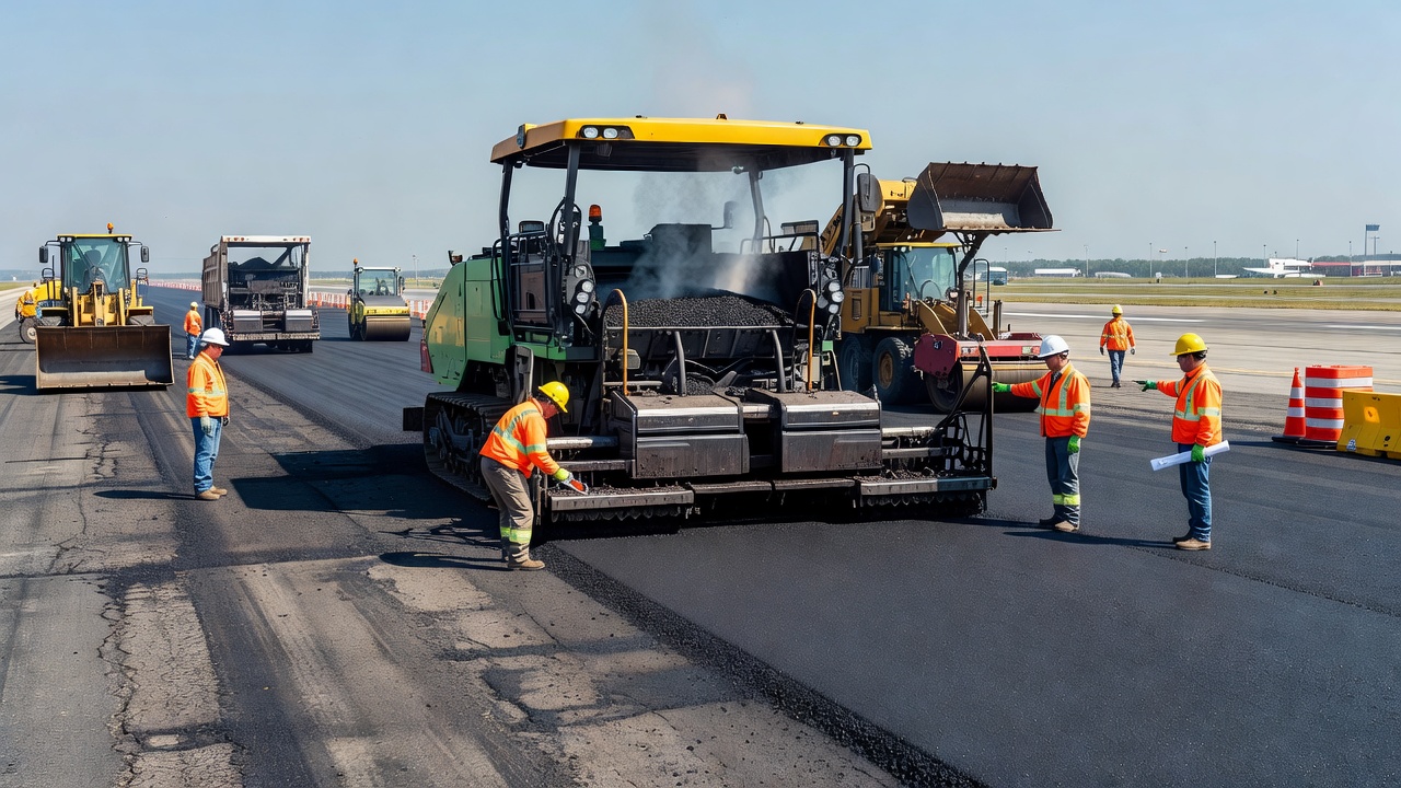
Item P-401 (Asphalt Mix Pavements) — hot mix asphalt (HMA) using the Superpave mix design system with Performance Grade (PG) binder selection per AASHTO M 320 or M 332. The FAA specifies three gradation types: Gradation 1 (19 mm NMAS) for heavy-load pavements with minimum 75 mm lift thickness, Gradation 2 (12.5 mm NMAS) for medium-load pavements with minimum 50 mm lift thickness, and Gradation 3 (9.5 mm NMAS) for leveling courses. Rutting performance testing using the Asphalt Pavement Analyzer (APA) per AASHTO T 340 is required at 64°C with 250 psi hose pressure, with maximum rut depth of 10 mm at 4,000 passes.
Item P-501 (Cement Concrete Pavement) — Portland cement concrete with minimum 28-day flexural strength of 4.5 MPa (650 psi) or minimum compressive strength of 27.6 MPa (4,000 psi). The concrete must contain air entrainment (4-7% total air content per ASTM C260) for freeze-thaw durability. Minimum slab thickness is 150 mm (6 inches). Joint spacing per FAA AC 150/5320-6G Section 3.16 uses dowels (smooth steel bars) at transverse joints and tie bars at longitudinal joints.
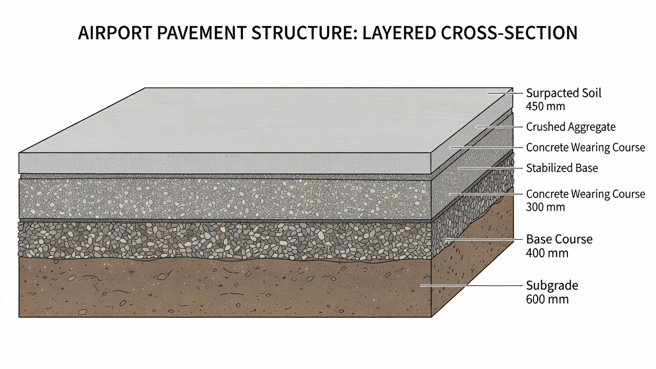
Per FAA AC 150/5320-6G Section 3 (Table 3-3 and Table 3-4), minimum layer thicknesses for airport reconstruction are:
| Layer | Flexible Pavement | Rigid Pavement |
|---|---|---|
| Asphalt surface (P-401) | 100 mm (4 inches) | N/A |
| Concrete surface (P-501) | N/A | 150 mm (6 inches) |
| Aggregate base (P-209) | 100 mm (4 inches) | 100 mm (4 inches) |
| Cement-treated base (P-304) | 100 mm (4 inches) | 100 mm (4 inches) |
| Subbase (P-154) | 100 mm (4 inches) | 100 mm (4 inches) |
| Total pavement structure | Per design (typically 300-800 mm) | Per design (typically 250-600 mm) |
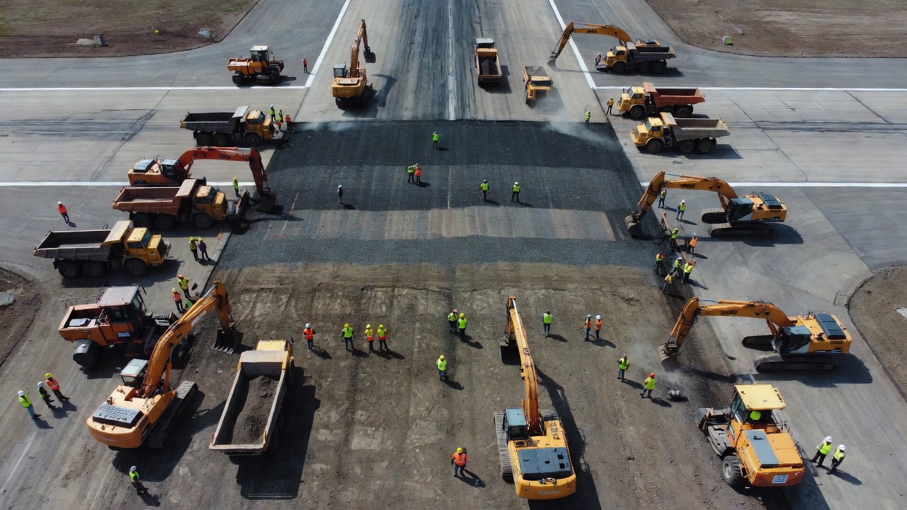
Airport pavement reconstruction presents unique challenges due to the need to maintain aircraft operations while construction is underway. The phasing of reconstruction work must balance construction quality, cost, and operational impact. Per FAA AC 150/5320-6G Section 1.8 (Staged Construction) , staged construction allows pavements to be built or reconstructed in phases to manage capital costs and operational impacts.
Based on operational requirements and construction window availability, airport reconstruction typically follows one of three phasing approaches:
Nightly Closures (Sequential Night Work) — the runway closes each night after the last scheduled flight, typically from 10:00 PM to 6:00 AM. Crews and equipment are escorted onto the airfield after shutdown and must clear the runway every morning in time for inspection and reopening to traffic. This approach allows airports to maintain full daytime operations but limits construction to 6-8 hours per night and 4-5 nights per week. Night work requires temporary airfield ground lighting (AGL), illuminated barricades, and compliance with FAA lighting standards (AC 150/5345-55). Productivity is approximately 30-50% of daytime construction due to reduced visibility, crew fatigue, and the time required for setup and teardown.
Extended Weekend Closures — the runway closes from Friday evening through Monday morning (typically 55-65 hours) for continuous construction. This approach provides longer, uninterrupted construction windows that improve productivity and quality (fewer cold joints, better compaction continuity). Weekend closures are commonly used at general aviation airports and smaller commercial service airports with lower weekend traffic volumes.
Full Extended Closure — the runway closes completely for a period of days to weeks (typically 14-60 days). This approach provides maximum construction productivity and quality but requires the airport to have an alternate runway capable of handling the design aircraft, or requires airlines to reduce operations or divert to other airports. Full closures are typically feasible only at airports with multiple runways or during periods of reduced demand.
Displaced Threshold Construction — the runway remains open but the landing threshold is displaced to avoid the construction zone. The active runway length is reduced, and runway markings, lighting, and signage are adjusted per FAA standards. Declared distances (TORA, TODA, ASDA, LDA) are recalculated and published in NOTAMs.
The FAA Airport Construction Impact Report (published quarterly) tracks major reconstruction projects and their operational impacts. Key constraints during reconstruction include:
Airfield Ground Lighting (AGL) — temporary lighting systems must comply with FAA AC 150/5345-55 and must be installed, tested, and certified before reopening the runway to night operations. Only edge lights, threshold lights, and runway end lights are absolutely necessary for minimum nighttime visibility; centerline and touchdown zone lights may be placed out of service during reconstruction.
Navigational Aids (NAVAIDS) — Instrument Landing Systems (ILS), Approach Lighting Systems (ALS), and Runway End Identifier Lights (REILs) are typically rendered out of service during reconstruction due to the difficulty of accommodating temporary shifts in their commissioned positions. Precision Approach Path Indicators (PAPI) are relatively easy to relocate with temporary foundations and rewiring.
Pavement Markings — temporary markings must be installed before reopening the runway to traffic. All obsolete markings must be removed (ground or painted over) to prevent pilot confusion. NOTAMs are issued to inform pilots of all changes to runway configuration, markings, and lighting.
Safety Requirements — the Airport Certification Manual (ACM) per 14 CFR Part 139 must be updated to reflect construction-related changes. A Construction Safety Plan (CSP) is required, addressing escorts, vehicle access, worker safety, FOD prevention, emergency response, and coordination with Air Traffic Control.
Life-cycle cost analysis (LCCA) is the formal process for comparing reconstruction with rehabilitation alternatives. Per FAA AC 150/5320-6G Section 1.6.3 (Cost Effectiveness Determination) , all federally funded airport projects involving pavement work must include a documented LCCA that follows a prescribed methodology:
The FAA LCCA methodology includes three steps:
Based on FAA cost data and industry research, the relative cost comparison between reconstruction and rehabilitation for airport pavements is:
| Intervention | Unit Cost (per sq yd, 2025 est.) | Design Life | Annualized Cost |
|---|---|---|---|
| Preventive maintenance (crack seal, seal coat) | $1-5 | 3-5 years | $0.20-1.67 |
| Thin overlay (50 mm asphalt) | $15-30 | 8-12 years | $1.25-3.75 |
| Structural overlay (100-150 mm asphalt) | $30-60 | 12-15 years | $2.00-5.00 |
| Full-depth reclamation (FDR with cement) | $20-40 | 10-15 years | $1.33-4.00 |
| Flexible reconstruction (full structure) | $50-150 | 20-30 years | $1.67-7.50 |
| Rigid reconstruction (full concrete) | $80-200 | 20-40 years | $2.00-10.00 |
Per the FAA’s PMP guidance (AC 150/5380-7B, Figure 1), maintaining a pavement in good condition throughout its life costs 4-5 times less than allowing it to deteriorate to poor condition and then rehabilitating it. The cost multiplier for reconstruction versus maintenance is even higher — typically 10-15 times more expensive to reconstruct than to maintain preventively.
The NPV (Net Present Value) comparison must include user delay costs, which can be substantial for airport reconstruction projects. Extended runway closures at major airports can cost airlines millions of dollars per day in lost revenue, delayed flights, and rerouting costs. Construction phasing that minimizes operational impacts — even at higher direct construction cost — may produce a lower total LCCA when user costs are included.
The expected performance of a reconstructed pavement is defined by its design life — the period over which the pavement is designed to carry the specified traffic loading without major structural rehabilitation. Per FAA AC 150/5320-6G Section 3.11 (Pavement Life) , design new pavements on federally funded FAA projects for a minimum 20-year design life. The FAA’s Extended Airport Pavement Life Program, announced through the ACPA (American Concrete Pavement Association) in March 2025, aims to double the expected life of runways at large hub airports from 20 to 40 years through improved designs, use of advanced materials, enhanced quality control during construction, and proactive maintenance programs.
Flexible (Asphalt) Pavements — properly designed and constructed flexible pavements with FAA P-401 surface, P-209 aggregate base, and stabilized subgrade typically achieve a remaining service life (RSL) of 18-25 years before the first major rehabilitation is needed, assuming the design traffic volume is not exceeded. The pavement condition (PCI) should remain above 85 for the first 5-7 years with routine preventive maintenance including crack sealing and minor patching. After year 7-10, the PCI will gradually decline to 70-85, at which point a structural overlay may be needed to extend the service life by an additional 10-15 years.
Rigid (Concrete) Pavements — properly designed and constructed rigid pavements with FAA P-501 concrete surface typically achieve a service life of 25-40 years before requiring major rehabilitation. The FAA’s Extended Airport Pavement Life Program specifically targets 40-year design life for concrete runways at large hub airports through: thicker concrete slabs (400-500 mm versus the traditional 300-400 mm), doweled joints with improved load transfer, optimized joint spacing, and use of high-performance concrete with supplementary cementitious materials (fly ash, slag cement).
The actual service life achieved by a reconstructed pavement depends on several factors that must be controlled during construction and throughout the pavement’s life:
Subgrade Quality — the most common cause of premature pavement failure is inadequate subgrade support. Subgrade CBR below the design value, non-uniform compaction, or undetected soft spots will cause differential settlement and structural cracking. Post-construction verification of subgrade CBR through DCP testing or modulus verification through FWD back-calculation is essential.
Construction Quality — compliance with FAA specifications for material quality, compaction, thickness, and smoothness directly affects performance. Inadequate compaction of base layers (below 100% of Modified Proctor) can cause consolidation rutting. Poor joint construction in concrete pavements causes faulting and spalling. Inadequate bond between asphalt layers causes delamination and premature fatigue failure.
Drainage — the FAA considers drainage “one of the most important factors affecting pavement performance” (AC 150/5320-6G Section 3.7). Pavements without adequate drainage can experience 2-3 times faster deterioration than well-drained pavements of the same thickness. Drainage layers, edge drains, and proper cross-slope (minimum 1.5%) must be included in reconstruction design.
Traffic Loading — if the actual aircraft traffic (gross weight, tire pressure, annual departures) exceeds the design traffic, the pavement will fail prematurely. The FAA recommends monitoring traffic through weigh-in-motion systems and annual departure counts, with structural evaluation every 5 years to verify the pavement is performing as designed.
Climate and Environment — freeze-thaw cycles, temperature extremes, and precipitation all affect pavement deterioration rates. In cold climates, frost-susceptible subgrade soils require consideration of frost protection thickness per FAA AC 150/5320-6G Section 3.14. In hot climates, asphalt binder grade selection (PG grading) must account for high pavement temperatures to prevent rutting. In wet climates, adequate drainage and moisture-resistant base materials are critical.
Research by the University of Illinois at Urbana-Champaign and the National Center for Asphalt Technology (NCAT) has developed performance models for reconstructed pavements. A typical PCI deterioration model for a well-constructed airport flexible pavement follows this pattern:
| Years Since Reconstruction | Expected PCI (with routine maintenance) | Expected PCI (without maintenance) |
|---|---|---|
| 0-2 | 100 | 100 |
| 3-5 | 90-100 | 85-95 |
| 6-8 | 80-90 | 70-85 |
| 9-12 | 70-85 | 55-70 |
| 13-15 | 60-75 | 40-55 |
| 16-18 | 50-65 | 30-45 |
| 19-20 | 40-55 | 20-35 |
The rate of deterioration accelerates after the pavement reaches a PCI of approximately 70-75, consistent with the FAA’s pavement condition life cycle curve. This acceleration point represents the optimal time for rehabilitation (typically a structural overlay) to extend the pavement’s service life by an additional 10-15 years, avoiding the much higher cost of a second reconstruction.
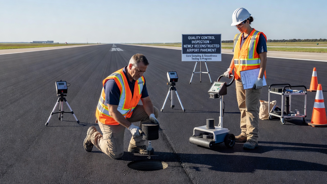
Quality control and quality assurance (QC/QA) inspection during and after reconstruction ensures that the new pavement meets the design specifications and will achieve the intended service life. The FAA’s AC 150/5370-10H (Standard Specifications for Construction of Airports) and AC 150/5100-14E (Architectural, Engineering, and Planning Consultant Services for Airport Grant Projects) establish the inspection framework.
Before reconstruction begins, the contractor must submit:
During construction, the inspector verifies compliance with the project specifications at each stage:
Subgrade Inspection — density testing per AASHTO T 310 (nuclear gauge) or ASTM D6938 at intervals specified in the QCP (typically every 200-400 linear meters per lane). Proof rolling with a heavy pneumatic roller. Moisture content verification per AASHTO T 310 to ensure compaction within the moisture content range specified (typically OMC ± 2%).
Base Course Inspection — thickness verification by measuring the difference between subgrade grade stakes and base surface grade stakes at maximum 30-meter intervals. Density testing at intervals of every 200-500 square meters. Gradation testing of produced base material per ASTM D6913 (sieve analysis) every 500-2,000 tons. CBR verification on compacted base material.
Asphalt Surface Inspection — P-401 — Mat temperature verification at the paver (typically 275-325°F for HMA, depending on binder grade and mix type). Compaction testing using nuclear density gauge per AASHTO T 355 at minimum 5 random locations per 500 tons of mix. In-place air voids determined from the density measurement, with target of 2-8% air voids (92-98% of Gmm). Smoothness testing using a rolling straightedge (3 m or 5 m) or profilograph, with typical maximum deviation of 3 mm in 3 m. Longitudinal joint density verified separately — the FAA considers joint density a separate pay item. Core samples are taken for laboratory verification of density, air voids, and gradation.
Concrete Surface Inspection — P-501 — Slump testing per ASTM C143 at the point of placement (typically 25-75 mm for slipform paving, 25-100 mm for fixed-form paving). Air content per ASTM C231 (pressure method) — target 4-7% total air for freeze-thaw durability. Compressive strength per ASTM C39 — minimum 4,000 psi (27.6 MPa) at 28 days, verified by field-cured cylinders (ASTM C31). Flexural strength per ASTM C78 — minimum 650 psi (4.5 MPa) at 28 days. Thickness verification by measuring from grade stakes and by cores taken at maximum 150-meter intervals. Joint construction — saw-cut timing (typically 4-12 hours after placement), joint depth (1/3 of slab thickness minimum), joint width (2-4 mm for saw-cut contraction joints). Curing — wet curing (burlap, wet sand, or ponding) for minimum 7 days, or curing compound per ASTM C309 applied at manufacturer-specified coverage rate.
After construction is complete, the following acceptance tests are performed:
Pavement Smoothness — measured using an inertial profiler per ASTM E950 (Class 1 profiler). The International Roughness Index (IRI) is computed from the profile data. Typical acceptance criteria for airport runways is IRI ≤ 1.5 m/km (95 inches/mile) at ride quality.
Surface Friction — measured using a continuous friction measuring equipment (CFME) per ASTM E274 or a micro GripTester. Minimum friction values per FAA AC 150/5320-6G vary by test method but typically require a coefficient of friction ≥ 0.50 for runways at the design speed.
Core Testing — cores extracted from the completed pavement (typically at intervals of 150-300 meters) are tested in the laboratory for: thickness (by direct measurement), density (by saturated surface-dry method per AASHTO T 166 for asphalt), air voids (by vacuum sealing method per AASHTO T 331, if required), gradation (by extraction of binder and sieve analysis), and for concrete pavement: thickness, compressive strength, and air content (by linear traverse per ASTM C457).
Falling Weight Deflectometer (FWD) Testing — deflection testing is performed on the completed pavement to verify structural uniformity and to establish a baseline for future performance monitoring. FWD testing per ASTM D4694 measures deflection basin parameters that relate to the structural capacity of the completed pavement. The results are compared with the design values to confirm that the as-constructed pavement meets the structural requirements.
Visual Inspection — a final visual inspection documents the as-constructed pavement condition including: surface appearance (uniform texture, color, and finish), joint condition (proper sealant installation, no spalling or raveling), edge condition (proper backfill at pavement edges), drainage (positive drainage, no ponding), and marking installation (all markings installed per FAA AC 150/5345-1).
The final deliverables for a reconstruction project include:
The FAA requires that all projects funded under the Airport Improvement Program (AIP) maintain inspection documentation for a minimum of 3 years after project completion. This documentation is essential for warranty enforcement and for tracking pavement performance to improve future design standards.
TarmacView provides expert pavement condition surveys, PCI assessments, and reconstruction feasibility evaluations for airport runways, taxiways, and aprons. Contact our team to schedule an inspection for your airfield pavements.
Reconstruction is the complete removal and replacement of a pavement structure from subgrade up, performed when the pavement has reached terminal condition and ...
Pavement rehabilitation encompasses major structural improvements to extend pavement service life beyond routine maintenance. It includes overlays, milling and ...
Airport pavement is the engineered surface for aircraft operations—runways, taxiways, aprons—designed to withstand heavy loads, ensure safety, and support airpo...