Aggregate Gradation in Pavement Materials
Aggregate gradation is the particle size distribution of the aggregate blend in asphalt or concrete, determined by sieve analysis. Gradation controls mixture de...
24 min read
Pavement Materials
Asphalt
+5
Pervious concrete (also called permeable or porous concrete) is a concrete with high interconnected void content (15-35%) allowing water to pass through, reducing runoff and recharging groundwater. Used for parking lots, shoulders, and low-traffic roads. Covers mix design, placement, clogging as a primary distress, and inspection for permeability maintenance.
Pervious concrete — also referred to as permeable concrete, porous concrete, gap-graded concrete, no-fines concrete, or enhanced porosity concrete (EPC) — is a specialized Portland cement concrete pavement material defined by the American Concrete Institute (ACI) in ACI 522R as a mixture of hydraulic cement, coarse aggregate of smaller size, admixtures, and water, with little or no fine aggregate (sand). The defining characteristic of pervious concrete is a system of highly permeable, interconnected voids that promote the rapid drainage of water, typically comprising 15% to 35% of the total material volume.
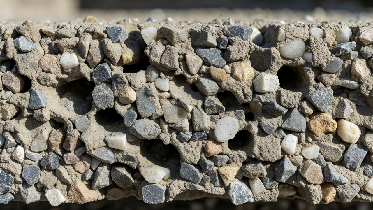
The fundamental engineering principle behind pervious concrete is the deliberate elimination of fine aggregate particles from the aggregate gradation. In conventional dense-graded concrete, aggregate particles span a continuous range of sizes from coarse gravel down to fine sand; the smaller particles fill the spaces between larger particles, producing a dense, tightly-packed structure with minimal void space. In pervious concrete, the aggregate is gap-graded or limited to a single nominal size, which means the interstitial spaces between coarse aggregate particles remain unfilled. The cement paste is proportioned to only coat and bind the aggregate particles at their contact points — not to fill the void space between them. This produces a hard, stable pavement with an internal network of connected channels through which water can freely flow.
This distinguishes pervious concrete fundamentally from conventional concrete in nearly every material property. The unit weight of pervious concrete is approximately 100 to 125 pounds per cubic foot (1,600 to 2,000 kg/m³), compared to 145 to 150 lb/ft³ for conventional concrete — a reduction of roughly 15% to 30% attributable to the void content. The material exhibits zero slump as measured by ASTM C143; it is a stiff, damp material that cannot be placed using conventional concrete handling methods. The compressive strength typically ranges from 2,500 to 4,000 psi (17 to 28 MPa), compared to 4,000 to 6,000 psi for conventional concrete, with flexural strengths of 150 to 550 psi (1.0 to 3.8 MPa). The lower strength is an acceptable trade-off for the material’s intended use in light-duty paving applications where structural loads are moderate but drainage performance is paramount.
The void content in pervious concrete is not the same as entrained air in conventional concrete. Entrained air in conventional concrete consists of microscopic, intentionally introduced air bubbles — typically 0.002 to 0.02 inches (0.05 to 0.5 mm) in diameter — that are isolated from each other and provide freeze-thaw protection through pressure relief. These bubbles constitute only 4% to 8% of the paste volume and do not connect to form drainage pathways. In pervious concrete, the voids are structural gaps between aggregate particles — typically 0.08 to 0.4 inches (2 to 10 mm) in diameter — that are fully interconnected, creating a continuous three-dimensional drainage network from the pavement surface to the subbase.
The mix design of pervious concrete follows fundamentally different principles from conventional concrete proportioning. The target is not maximum density and strength, but rather a controlled balance between void content (for permeability), paste coating thickness (for durability and raveling resistance), and compressive strength (for structural adequacy). The governing standards include ACI 522.1-13 (Specification for Pervious Concrete Pavement), ASTM C1688 (Density and Void Content of Freshly Mixed Pervious Concrete), and the NRMCA Pervious Concrete Mixture Proportioning methodology.
Pervious concrete uses single-sized or narrowly graded coarse aggregate conforming to ASTM C33. The most commonly specified gradations are:
| ASTM Gradation | Size Range | Typical Applications |
|---|---|---|
| No. 67 | 3/4 in. to No. 4 (19 mm to 4.75 mm) | Parking lots, heavy pedestrian |
| No. 7 | 1/2 in. to No. 8 (12.5 mm to 2.36 mm) | General pavement |
| No. 8 | 3/8 in. to No. 16 (9.5 mm to 1.18 mm) | Pedestrian, thin overlays |
| No. 89 | 3/8 in. to No. 50 (9.5 mm to 0.30 mm) | Decorative, light traffic |
The aggregate-to-cement ratio typically ranges from 4:1 to 5:1 by mass, producing aggregate contents of approximately 2,000 to 2,500 pounds per cubic yard (1,190 to 1,480 kg/m³). The ideal aggregate void content in the loose or rodded condition should be in the high 30s to low 40s percent, as measured by ASTM C29. Both rounded (gravel) and crushed (angular) aggregates can be used, though crushed aggregates provide better interlock at the cost of requiring more compaction effort.
Cement content in pervious concrete typically ranges from 450 to 700 pounds per cubic yard (267 to 416 kg/m³), with the NRMCA recommending 450 to 550 lb/yd³ as the most desirable range for balancing workability and durability. Excessively high cement contents — above 600 lb/yd³ — combined with very low water-to-cement ratios (0.25 to 0.28) create a condition known as dead cement, where a significant portion of the cement remains unhydrated, producing weakened paste that reduces raveling resistance.
Supplementary cementitious materials (SCMs) are commonly used to improve workability, reduce heat of hydration, and enhance durability:
The water-to-cementitious materials ratio (w/cm) for pervious concrete is a critical parameter with a narrow acceptable window of 0.27 to 0.36 per ACI 522R. The NRMCA further narrows this to 0.34 to 0.41 for optimal workability and cement hydration:
| w/cm Ratio | Effect |
|---|---|
| Below 0.27 | Balling of mix, poor compaction, unhydrated cement, reduced strength |
| 0.27 to 0.34 | Acceptable range; requires high-range water reducers for workability |
| 0.34 to 0.41 | Optimal range per NRMCA; produces wet metallic sheen on aggregate |
| Above 0.40 | Paste runoff; voids become sealed; reduced permeability |
The correct water content produces a characteristic wet, metallic sheen on the aggregate particles without runoff of the paste. A practical field test — the handful test — involves forming a ball of the mixture in the gloved hand: the ball should hold its shape without crumbling, yet when released, the individual aggregate particles should remain discernible rather than being embedded in a paste matrix.
Pervious concrete requires a tailored admixture package to achieve acceptable placement characteristics and durability:
High-range water reducers (HRWR) — Type A or Type F per ASTM C494 — are used to improve workability at the low w/cm ratios required. However, caution is needed because excessive superplasticization can cause the paste to drain down from the aggregate and collect at the bottom of the pavement section, sealing the lower voids and reducing permeability.
Viscosity-modifying admixtures (VMA) help maintain the paste coating on the aggregate surface and prevent drain-down during placement and compaction. These are particularly important in hot weather when the mixture’s rheology changes rapidly.
Hydration stabilizers — also called set retarders or hydration-control admixtures — are strongly recommended for pervious concrete. The high void content exposes a large surface area of paste to the air, accelerating moisture loss and shortening the working time. Hydration stabilizers can extend the working window from approximately 30 minutes to 2+ hours, which is critical given that pervious concrete cannot be pumped and requires direct discharge from the truck.
Air-entraining admixtures (AEA) are required for pervious concrete in freeze-thaw environments. However, a unique challenge is that the air content cannot be directly measured or verified using standard concrete air-content test methods (ASTM C231 pressure method or ASTM C173 volumetric method) because the large structural voids cause erroneous readings. Air content in the paste fraction of pervious concrete is best evaluated using ASTM C457 (microscopic air-void analysis of hardened concrete) on extracted cores.
The NRMCA mixture proportioning method for pervious concrete calculates the required paste volume using this relationship:
Vp = Vac + CI − Vvoid
Where:
This approach ensures that the paste volume is sufficient to coat all aggregate particles and provide durable bonding at contact points, while leaving the target void volume open for water transmission.
| Test Standard | Purpose | Target Value |
|---|---|---|
| ASTM C1688 | Fresh density and void content | Unit weight ±5 lb/ft³ of target |
| ASTM C1754 | Hardened density and void content (cores) | Target void % ±2% |
| ASTM C39 | Compressive strength (cylinders) | 2,500-4,000 psi |
| ASTM C78 | Flexural strength (beams) | 150-550 psi |
| ASTM C1701 | Field infiltration rate | 200-500 in/hr (new construction) |
ASTM C1688 is the primary quality-control test and replaces the slump test for pervious concrete. The test involves consolidating a known volume of fresh concrete in a standard container using a specific compaction procedure (typically 20 drops of a standard tamping rod in three layers), then weighing the filled container to determine the fresh density. This density is compared to the theoretical maximum density (calculated from known specific gravities and proportions) to determine the fresh void content.
Pervious concrete placement requires specialized construction procedures that differ significantly from conventional concrete paving. The material is zero-slump, cannot be pumped, and has a limited working window that demands precise coordination between mixing, delivery, and placement operations.
The subgrade must be prepared to provide adequate support and drainage. Typical requirements include:
Pervious concrete is placed using fixed-form construction methods. The forms are set to a height that allows the strike-off to be positioned approximately 0.5 to 0.75 inches (12 to 20 mm) above the final pavement elevation, accounting for the reduction in thickness that occurs during compaction.
The material must be discharged directly from the mixer truck into the placement area and spread using rakes or shovels. Because pervious concrete cannot be pumped, the mixer truck must have direct access to all areas of the pavement. For large projects, multiple access points or a paving train may be required.
Mechanical or manual vibrating screeds are used for initial consolidation and striking off to grade. However, the vibration frequency must be reduced compared to conventional concrete to avoid over-compaction of the top surface, which can seal the surface voids and dramatically reduce permeability. Laser screeds can be used but require careful adjustment of vibration settings.
Compaction is the most critical step in pervious concrete construction and is performed using steel rollers typically 3 to 6 feet (1 to 2 m) wide, operated in non-vibratory mode. The roller consolidates the concrete to the final grade (form height) and ensures adequate contact between aggregate particles for strength development.
Typical compaction requirements include:
The compaction process must be carefully controlled: insufficient compaction reduces strength and increases raveling potential, while excessive compaction can collapse the void structure and reduce permeability below design targets.
Curing is arguably the most critical and most frequently neglected step in pervious concrete construction. Because pervious concrete does not bleed — water does not rise to the surface as it does in conventional concrete — the material is highly susceptible to plastic shrinkage cracking within the first hours after placement. The exposed surface area of the voids accelerates moisture evaporation from the paste.
The required curing sequence is:
Liquid membrane-forming curing compounds are not recommended for pervious concrete. Research by Kevern et al. (2009) demonstrated that membrane curing compounds reduce surface evaporation but do nothing to prevent internal moisture loss through the open void structure. Only physical moisture barriers — polyethylene sheeting or wet burlap covered with plastic — provide adequate curing.
Control joints in pervious concrete are typically installed using a rolling joint tool — similar to a pizza cutter with a cutting blade — that creates a weakened plane approximately 25% of the slab thickness deep. Joint spacing is typically 20 feet (6 m), though some installations have successfully used spacings up to 45 feet without uncontrolled cracking.
Saw-cutting is strongly discouraged for pervious concrete joints because:
Some pervious concrete installations omit control joints entirely, accepting that random cracking will occur. Because the pavement is typically underlain by a flexible stone reservoir, differential movement at cracks is minimal, and the structural and functional impacts are generally acceptable.
Pervious concrete cannot be placed on frozen, muddy, or saturated subgrade. Rain during placement is particularly problematic because water droplets impact the exposed paste surface, creating surface sealing and pitting. High ambient temperatures (above 85°F / 30°C), low humidity, and high winds accelerate moisture evaporation and require adjustments to the mixture (hydration stabilizers) and placement procedures (faster operations, immediate curing).
The permeability of pervious concrete is measured by the infiltration rate — the velocity at which water passes vertically through the pavement under a given hydraulic head. This property is governed by ASTM C1701/C1701M, Standard Test Method for Infiltration Rate of In Situ Pervious Concrete.
Newly placed pervious concrete with a properly designed and compacted void structure exhibits infiltration rates in the range of:
| Void Content | Typical Infiltration Rate | Equivalent Hydraulic Conductivity |
|---|---|---|
| 15% | 100-200 in/hr (0.07-0.14 cm/s) | 2.5-5.1 m/hr |
| 20% | 200-400 in/hr (0.14-0.28 cm/s) | 5.1-10.2 m/hr |
| 25% | 400-800 in/hr (0.28-0.56 cm/s) | 10.2-20.3 m/hr |
| 30% | 800-1,500 in/hr (0.56-1.06 cm/s) | 20.3-38.1 m/hr |
The commonly cited design infiltration rate for pervious concrete is 200 to 500 inches per hour (0.14 to 0.35 cm/s). These rates are orders of magnitude higher than natural rainfall intensities — even a 100-year, 1-hour storm event in most regions produces rainfall intensities of only 2 to 6 inches per hour — meaning the surface infiltration capacity of pervious concrete virtually never limits the hydrologic performance. The actual system performance is governed by the subbase storage volume and the subgrade infiltration rate.
The ASTM C1701 field test involves the following procedure:
I = (K × M) / (D² × t)
Where:
The permeability of pervious concrete is not solely a function of total void content — the connectivity of the void network is equally or more important. Two specimens with identical total void content can have dramatically different permeabilities if one has well-connected pores and the other has isolated voids. Factors that influence void connectivity include:
Clogging — the progressive accumulation of sediment, organic debris, and fine particles within the interconnected void system — is the primary distress mechanism for pervious concrete. Unlike conventional concrete pavements, where structural distresses (cracking, spalling, joint deterioration) dominate the failure modes, pervious concrete most commonly fails functionally long before it fails structurally.
Three distinct mechanisms contribute to the clogging of pervious concrete:
Surface deposition — Windblown soil, dust, and sand from adjacent unpaved areas, agricultural fields, or construction sites accumulate on the pavement surface. Rainfall then transports these particles into the surface voids. Coarse sand particles (0.5 to 1.0 mm) that are larger than the surface pore throats form a surface seal — a thin, low-permeability layer that prevents water entry while the deeper void structure remains open.
Depth filtration — Medium and fine sand particles (0.075 to 0.5 mm) enter the surface voids and are transported downward through the pore network. These particles are trapped at pore throats — the constrictions between adjacent aggregate particles where the pore diameter is smallest. This creates a clogging front that progresses from the surface downward. The concentration of trapped sediment decreases exponentially with depth, with 60% to 80% of clogging material typically found in the top 0.5 to 1.0 inches (12 to 25 mm) of the pavement.
Clay adhesion — Clay particles (smaller than 0.002 mm) pose the most severe clogging challenge. When wet, clay particles can pass relatively freely through the pore network. However, when the pavement dries between rainfall events, the clay particles adhere strongly to the rough, tortuous pore walls through a combination of van der Waals forces, capillary suction, and mechanical interlocking. Research by Rao et al. (2022) demonstrated that after clay clogging and subsequent drying, the normalized permeability dropped to 0.154 of the initial value, and pressure washing achieved only 4.91% permeability recovery — confirming that dried clay is extremely difficult to remove from pervious concrete pores.
| Source | Typical Material | Particle Size |
|---|---|---|
| Adjacent bare soil | Silt, clay, fine sand | <0.075 to 0.5 mm |
| Landscaping mulch | Organic fines | Variable |
| Winter sand applications | Medium to coarse sand | 0.5 to 2.0 mm |
| Vehicle tire wear | Rubber particles | 0.01 to 0.5 mm |
| Atmospheric deposition | Dust, pollen | <0.01 to 0.1 mm |
| Leaf litter decomposition | Organic debris, biofilm | Variable |
| Construction site runoff | Silt, clay | <0.002 to 0.075 mm |
Research has documented extreme reductions in infiltration capacity due to clogging:
The inspection of pervious concrete focuses on functional performance assessment — measuring the material’s ability to transmit water — rather than the structural condition evaluation that dominates conventional concrete inspection.
The primary inspection method is ASTM C1701 infiltration testing, which should be performed:
A minimum of three test locations per pavement section is recommended, with additional testing at:
Visual inspection provides rapid qualitative assessment of clogging conditions:
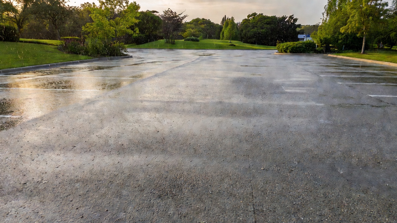
Surface ponding — Water remaining on the pavement surface more than 30 minutes after rainfall cessation is the most direct indicator of clogging. Ponding may be localized (indicating isolated clogged areas) or widespread (indicating system-wide permeability loss).
Surface discoloration — Accumulation of fine sediment appears as a dusty or muddy discoloration, particularly along pavement edges, at low points, and in wheel paths. Dark staining indicates organic accumulation or biofilm formation.
Vegetation growth — Moss, algae, or weeds growing on the pavement surface indicate persistent moisture retention and organic accumulation — both of which reduce permeability. In the Pacific Northwest, green, slick surfaces from moss growth are a key indicator of clogged pervious concrete.
Loss of visible surface texture — The distinct, rough surface texture of pervious concrete becomes smooth and sealed-looking as sediment fills the surface voids. A surface that appears similar to conventional concrete likely has significant clogging.
When field testing indicates significant performance degradation, the following advanced methods can quantify the extent and depth of clogging:
Core extraction and laboratory analysis — Cores 4 to 6 inches (100 to 150 mm) in diameter are extracted per ASTM C42 and tested for:
Sectional core analysis — Cores are horizontally sectioned into wafers 0.25 to 0.5 inches (6 to 12 mm) thick, and each wafer is individually tested for permeability and sediment content. This method reveals the vertical distribution of clogging material and identifies whether clogging is surface-only or full-depth.
Effective maintenance of pervious concrete requires a proactive, preventative approach rather than reactive restoration. The most critical principle — confirmed by extensive research — is that maintenance must be performed before deep, irreversible clogging occurs.
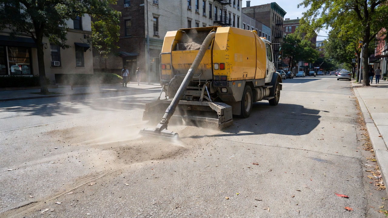
Regenerative-air vacuum sweeping is the most effective large-area maintenance method for pervious concrete. Unlike mechanical broom sweepers, which redistribute fine material without removing it, regenerative-air sweepers use a high-velocity air stream (500 to 700 ft/s at the nozzle) to lift sediment from surface pores combined with a vacuum system to capture it.
| Parameter | Specification |
|---|---|
| Sweeper type | Regenerative-air or vacuum-assisted |
| Operating speed | 3 to 5 mph (5 to 8 km/h) |
| Air velocity at nozzle | Minimum 500 ft/s (150 m/s) |
| Frequency | Minimum annually; quarterly in high-sediment areas |
| Passes | Two passes in each direction for heavily loaded sections |
Properly performed vacuum sweeping can restore 80% to 90% of original permeability when the pavement is not deeply clogged. The FHWA recommends focusing on the first 50 to 100 feet (15 to 30 m) of pavement from unpaved access points, where sediment loading is typically highest.
For pavements where vacuum sweeping alone is insufficient, high-pressure water washing at 2,000 to 4,000 psi (14 to 28 MPa) with simultaneous vacuum recovery of the wash water is the most effective deep-cleaning method. The rotating nozzle system directs water into the pavement pores at a downward angle, dislodging embedded sediment, while the vacuum system recovers the sediment-laden water before it can re-enter the pore structure.
Critical operational requirements:
The pressure washing method is most effective at the near-surface, where the scouring force of the water jet is greatest. The effectiveness diminishes with depth because the aggregate skeleton blocks direct water access to deeper pores.
When infiltration rates fall below approximately 10% of the as-constructed value, more aggressive restoration may be required:
The following actions must never be performed on pervious concrete:
The freeze-thaw durability of pervious concrete has been a subject of significant research and debate since the material gained widespread use in the 1990s. The key concern is that water retained in the pore structure expands upon freezing by approximately 9%, and if the concrete is critically saturated (voids filled with water to more than 91% of total void volume), the expansion generates internal pressures that can exceed the tensile strength of the thin cement paste coating, causing cracking, scaling, and raveling.
Properly designed and maintained pervious concrete does not remain saturated because water drains freely through the interconnected voids. Freeze-thaw damage occurs when:
Research by Schaefer et al. (2006) and Kevern et al. (2008) at Iowa State University, supported by the NRMCA and the Portland Cement Association, established three proven strategies for freeze-thaw durability:
Air-entrained paste — Air-entraining admixtures create microscopic air bubbles in the cement paste (spacing factor below 0.01 inches / 0.25 mm) that relieve hydraulic pressure during freezing. While the total air content of the pervious concrete cannot be measured by conventional test methods (because the structural voids dominate the reading), the air-void system in the paste fraction can be verified by ASTM C457 on hardened specimens.
Addition of fine aggregate — Including 5% to 7% sand by weight of total aggregate has been shown to significantly improve freeze-thaw durability. In laboratory testing, mixtures with 7% sand and air entrainment achieved only 2% mass loss after 300 freeze-thaw cycles — well within acceptable limits. The sand improves the density and strength of the paste fraction without substantially reducing permeability.
Thick, drainable aggregate base — The stone reservoir beneath the pervious concrete must be deep enough to store water below the frost penetration depth. The NRMCA classifies freeze-thaw zones as follows:
| Freeze-Thaw Zone | Characteristics | Recommended Base Depth |
|---|---|---|
| Dry Freeze | 15+ cycles/year, little winter precipitation | 4-8 inches (100-200 mm) |
| Hard Dry Freeze | Dry freeze + ground frozen continuously | 4-8 inches (100-200 mm) |
| Wet Freeze | 15+ cycles/year, winter precipitation | 4-8 inches (100-200 mm) |
| Hard Wet Freeze | Wet freeze + ground frozen continuously | 8-24 inches (200-600 mm) with underdrain |
Multiple long-term field installations have demonstrated successful freeze-thaw performance:
Pervious concrete is not recommended in freeze-thaw environments where the water table rises to within 3 feet (1 m) of the pavement surface, as the constant moisture supply prevents the pavement from draining between freeze events.
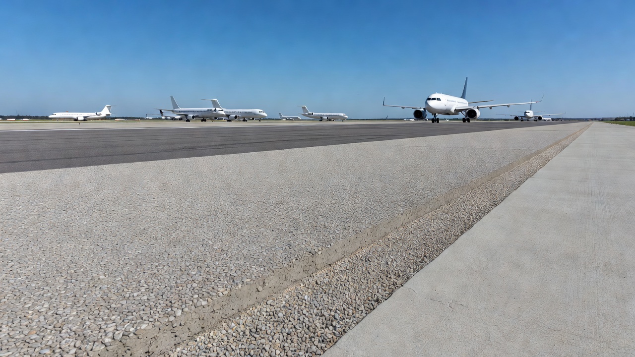
Pervious concrete has specific applications at airports, primarily in low-traffic areas where aircraft loading is light and the benefits of rapid stormwater drainage are significant.
ICAO Annex 14, Volume I, Chapter 3 establishes Standards and Recommended Practices (SARPs) requiring that runway surfaces provide good friction characteristics when wet. While pervious concrete is not explicitly mentioned in ICAO Annex 14, the drainage principles it embodies — rapid removal of surface water to maintain tire-pavement contact — directly support compliance with these requirements.
ICAO Doc 9157 (Aerodrome Design Manual, Part 3 — Pavements, 3rd edition, 2022) provides detailed guidance on pavement design and evaluation for airports. The manual addresses subsurface drainage, permeable base courses, and the importance of preventing water accumulation in pavement structures — all areas where pervious concrete can make a direct contribution.
FAA Advisory Circular 150/5320-6G (Airport Pavement Design and Evaluation, June 2021) is the primary FAA guidance document for airport pavement design in the United States. While the AC does not currently include specific design provisions for pervious concrete as a structural surface course, the FAA’s guidance on pavement drainage, edge drains, and open-graded base courses in Chapter 6 (Drainage and Subdrainage) establishes the design framework applicable to pervious concrete systems.
| Application | Typical Configuration | Aircraft Loading |
|---|---|---|
| Pavement shoulders | 4-6 in. pervious concrete over 6-12 in. reservoir stone | Minimal — emergency only |
| General aviation aprons | 6 in. pervious concrete over 12-24 in. reservoir stone | Design Group I-II aircraft |
| Fire station aprons | 6 in. pervious concrete over 12 in. reservoir stone | Emergency vehicles only |
| Service roads | 5-6 in. pervious concrete over 8-12 in. reservoir stone | Light service vehicles |
| Employee parking lots | 5-6 in. pervious concrete over 8-12 in. reservoir stone | Automobiles only |
| Drainage channels | 4-6 in. pervious concrete lining | No structural load |
Pervious concrete’s compressive strength of 2,500 to 4,000 psi limits its application to aircraft with single-wheel loads below approximately 12,500 pounds (55.6 kN) — equivalent to FAA Airport Design Group I and small Group II aircraft (general aviation aircraft, business jets, and small turboprops).
For applications involving heavier aircraft, pervious concrete can be used as a permeable base course beneath a conventional rigid pavement surface. In this configuration, the pervious concrete layer — typically 6 to 10 inches (150 to 250 mm) thick — provides both structural support and subsurface drainage, allowing stormwater to be collected and conveyed within the pavement structure rather than flowing across the surface. The FAA AC 150/5320-6G addresses this concept in its discussion of pavement subdrainage and permeable base courses.
The application of pervious concrete at airports provides specific hydrological benefits:
Pervious concrete provides significant sustainability benefits across multiple environmental dimensions, making it a recognized green infrastructure practice under the US Environmental Protection Agency’s (EPA) stormwater management framework.
The most immediate sustainability benefit of pervious concrete is its ability to reduce stormwater runoff. The EPA recognizes pervious concrete as a Best Management Practice (BMP) for stormwater management under the NPDES permitting program. Research has documented that effective pervious concrete systems can reduce surface runoff by up to 80% or more compared to conventional impervious surfaces (Ferguson, 2005).
The pervious concrete system captures the first flush — the initial, most polluted portion of rainfall — and infiltrates it into the subgrade, preventing the transport of accumulated pollutants from the pavement surface to receiving waters. This first-flush capture is particularly effective for parking lots, where vehicle-deposited contaminants (oil, grease, heavy metals) are most concentrated at the beginning of a rainfall event.
By allowing stormwater to infiltrate the subgrade, pervious concrete returns precipitation to the natural hydrologic cycle. Developed impervious surfaces typically return only 10% to 30% of annual precipitation to groundwater, with the remainder becoming surface runoff. Pervious concrete systems with high subgrade infiltration rates can return 80% to 100% of annual precipitation to the groundwater table, maintaining baseflow in streams and replenishing aquifer supplies.
As stormwater percolates through the pervious concrete and the underlying subgrade, natural physical, chemical, and biological processes remove pollutants:
| Pollutant | Removal Efficiency | Mechanism |
|---|---|---|
| Total Suspended Solids (TSS) | 80-90% | Filtration through pavement and subgrade |
| Total Phosphorus | 50-70% | Adsorption to soil particles |
| Total Nitrogen | 30-50% | Biological uptake, denitrification |
| Copper, Zinc, Lead | 70-95% | Adsorption, precipitation |
| Oil and Grease | 80-90% | Biological degradation, filtration |
| Pathogens | 60-90% | Filtration, UV exposure, die-off |
The water quality treatment provided by pervious concrete systems can help airport and municipal operators meet Total Maximum Daily Load (TMDL) requirements for impaired waterways.
Pervious concrete reduces the urban heat island effect through three mechanisms:
Studies have documented that pervious concrete surfaces can be 5°F to 15°F (3°C to 8°C) cooler than conventional asphalt surfaces under identical solar loading conditions.
The US Green Building Council’s LEED (Leadership in Energy and Environmental Design) rating system recognizes pervious concrete through multiple credits:
| LEED Credit | Description | Contribution |
|---|---|---|
| SS Credit 6.1 | Stormwater Design — Quantity Control | Reduces runoff rate and volume |
| SS Credit 6.2 | Stormwater Design — Quality Control | Filters pollutants through natural treatment |
| SS Credit 7.1 | Heat Island Effect — Non-Roof | Light-colored surface with high reflectance |
| WE Credit 1 | Water Efficient Landscaping | Subbase reservoir stores stormwater for irrigation use |
| MR Credits 4-5 | Recycled Content and Regional Materials | SCMs count as recycled content; local aggregate sourcing |
| ID Credit 1 | Innovation in Design | Integrated stormwater management approach |
Pervious concrete systems can reduce or eliminate the need for conventional stormwater management infrastructure including storm sewers, catch basins, retention ponds, detention basins, curb and gutter systems, and associated piping. This infrastructure reduction provides multiple benefits:
The open void structure of pervious concrete absorbs sound at the tire-pavement interface, reducing traffic noise by 2 to 4 dB(A) compared to conventional concrete pavements. This noise reduction is particularly beneficial for airport applications where apron and service road traffic contributes to ambient noise levels.
The following standards and reference documents govern the design, construction, testing, and maintenance of pervious concrete:
| Standard | Title | Application |
|---|---|---|
| ACI 522R-23 | Pervious Concrete (Report) | Comprehensive guide to materials, design, construction |
| ACI 522.1-13 | Specification for Pervious Concrete Pavement | Construction specification requirements |
| ASTM C1688/C1688M | Density and Void Content of Freshly Mixed Pervious Concrete | Primary QC test for fresh concrete |
| ASTM C1701/C1701M | Infiltration Rate of In Situ Pervious Concrete | Field permeability testing |
| ASTM C1754/C1754M | Density and Void Content of Hardened Pervious Concrete | Core acceptance testing |
| ASTM C42/C42M | Obtaining and Testing Drilled Cores | Core sampling methodology |
| ASTM C33/C33M | Concrete Aggregates | Aggregate gradation specifications |
| ASTM C494/C494M | Chemical Admixtures for Concrete | HRWR, retarder specifications |
| ASTM C457 | Air-Void Analysis of Hardened Concrete | Freeze-thaw air content verification |
| Document | Author | Title |
|---|---|---|
| PIP 1 | NRMCA | Specifying Pervious Concrete |
| PIP 3 | NRMCA | Acceptance Testing of Pervious Concrete |
| PIP 4 | NRMCA | Mix Design of Pervious Concrete |
| PIP 5 | NRMCA | Construction of Pervious Concrete Pavements |
| HIF-13-006 | FHWA | Pervious Concrete — Materials, Properties, and Construction |
| BMP Fact Sheet | US EPA | Pervious Concrete Pavement |
| Document | Title | Application |
|---|---|---|
| ICAO Annex 14 Vol. I | Aerodrome Design and Operations | Runway surface requirements |
| ICAO Doc 9157 Part 3 | Aerodrome Design Manual — Pavements | Pavement design and drainage |
| FAA AC 150/5320-6G | Airport Pavement Design and Evaluation | Structural design for airfields |
| FAA AC 150/5320-12C | Skid-Resistant Airport Pavement Surfaces | Surface friction requirements |
TarmacView's AI-powered inspection platform detects clogging, permeability loss, and surface distress on pervious concrete pavements and permeable pavement systems for airports and infrastructure.
Aggregate gradation is the particle size distribution of the aggregate blend in asphalt or concrete, determined by sieve analysis. Gradation controls mixture de...
Cementitious grouting uses fluid cement-based mixtures poured or pumped to fill cracks, voids, or spaces in concrete — including tendon duct grouting, crack inj...
Roller-Compacted Concrete (RCC) is a zero-slump concrete placed with asphalt paving equipment and compacted with vibratory rollers, providing a strong, durable ...