A bridge pier is an intermediate vertical support structure between abutments that transfers superstructure loads to the foundation. Multi-column bents, wall piers, and hammerhead piers are common types. Pier condition — cracking, spalling, scour, collision damage, corrosion — is a SNBI substructure rating element. Covers pier types, distress modes, and inspection approaches.
A bridge pier is an intermediate vertical support structure, positioned between abutments, that transmits loads from the bridge superstructure — including the deck, girders, live traffic loads, and environmental loads — down to the foundation system. Unlike abutments, which function both as vertical supports and as earth-retaining structures at the bridge ends, piers are freestanding intermediate supports that do not retain fill. Piers are classified as substructure elements under the FHWA Specifications for the National Bridge Inventory (SNBI) and are subject to specific condition rating protocols under the National Bridge Inspection Standards (NBIS) codified in 23 CFR 650 Subpart C.
Definition and Structural Role
A bridge pier serves as the intermediate vertical support that transfers all superstructure dead load, live load, wind load, stream flow load, ice load, seismic load, and collision load to the foundation and ultimately to the bearing stratum. The structural function of a pier is analogous to that of a building column but subjected to more complex horizontal loading conditions from water, wind, seismic events, and vehicle or vessel impact.
The pier transmits the following load types to the foundation:
Dead loads — self-weight of the superstructure (deck, girders, diaphragms, wearing surface, barriers, utilities) plus self-weight of the pier itself. For a typical reinforced concrete pier, the self-weight can account for 15-25% of the total vertical load at the foundation level.
Live loads — vehicular traffic loads including the AASHTO HL-93 design truck, lane load, and permit vehicles. The AASHTO LRFD Bridge Design Specifications (9th Edition, 2020) require that live load distribution to piers account for multiple loaded lanes, dynamic load allowance (33% for the design truck), and the appropriate reduction factors per AASHTO Table 3.6.1.1.2-1.
Wind loads — applied to the exposed surface of the superstructure and the pier itself. AASHTO Section 3.8 specifies a base wind pressure of 0.050 ksf for the structure and 0.040 ksf for the live load at 100 mph wind speed. Wind pressure on piers is calculated using the drag coefficient method, with coefficients ranging from 1.0 for circular sections to 1.4 for rectangular sections.
Stream flow loads — hydrodynamic pressure from flowing water acting on the pier. AASHTO Section 3.7 specifies stream pressure calculated as p = 0.5 × Cd × ρ × V², where Cd is the drag coefficient (0.7 for circular, 1.4 for square), ρ is the density of water (1.94 slugs/ft³), and V is the design stream velocity. For a pier in a river with a 10 ft/s flow velocity, the stream pressure can reach 200 psf on the upstream face.
Ice loads — horizontal pressure from ice sheets impacting or adhering to the pier. AASHTO specifies ice crushing strength values ranging from 70 psi for warm ice near the melting point to 200 psi for cold ice at -20°F. The ice force on a pier is calculated as F = p × w × t, where p is the crushing strength, w is the pier width, and t is the ice thickness.
Collision loads — vehicle impact on piers adjacent to roadways (AASHTO specifies 600 kips applied at 5 ft above ground for highway impacts) and vessel collision on navigable waterways (forces can exceed 10,000 kips for large ships).
Seismic loads — inertial forces generated during earthquake events. AASHTO Section 3.10 specifies the design response spectrum based on the 7% probability of exceedance in 75 years seismic hazard maps from USGS, using Site Class (A through F) modifiers.
The pier must also resist buoyancy forces when founded below the groundwater table or submerged during flood events. AASHTO requires that the weight of the pier under submerged conditions be reduced by the weight of displaced water per Archimedes’ principle.
Pier Types
Bridge piers are classified into five primary types based on their structural configuration, construction method, and load path. The selection of pier type depends on span length, bridge width, hydraulic conditions, seismic demands, foundation conditions, construction cost, and aesthetic requirements.
Solid Wall Piers
Solid wall piers consist of a continuous vertical wall extending from the foundation to the superstructure. They are the simplest and most common pier type for bridges with moderate span lengths (30-80 ft). Solid wall piers can be constructed with rectangular cross-sections, with or without architectural reveals, and may incorporate openings (voids) to reduce weight and allow water or debris passage.
Key characteristics:
Typical thickness: 12-36 inches for reinforced concrete
Typical height range: 10-40 ft
Reinforcement: Two layers of reinforcement in each direction, minimum 0.5% vertical steel ratio per AASHTO LRFD Section 5.7.4.2
Hydraulic performance: Poor — solid walls create the largest obstruction to flow, leading to higher scour potential
Solid wall piers are most appropriate for dry land applications or short crossings over low-flow streams where hydraulic concerns are minimal. They are frequently used in conjunction with spread footings on competent rock or stiff soil.
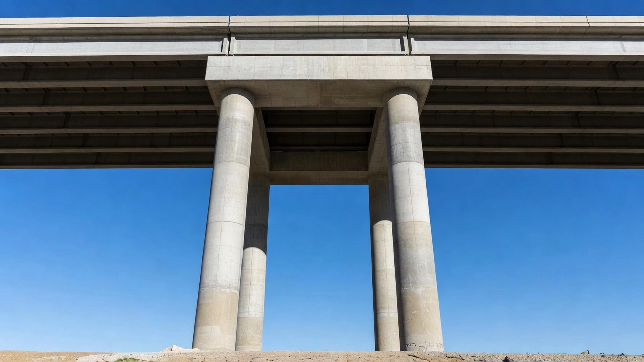
Multi-Column Bent Piers
Multi-column bent piers consist of two or more vertical columns supporting a common pier cap beam. The columns may be circular, rectangular, octagonal, or any geometric section. This is the most widely used pier type for modern highway bridges in the United States.
Key characteristics:
Column spacing: 12-30 ft center-to-center, depending on bridge width and span configuration
Column diameter (circular): 24-72 inches for typical highway bridges
Column dimensions (rectangular): Minimum 18 inches in any direction per AASHTO
Cap beam dimensions: Depth typically L/10 to L/12 of column spacing; width equal to bearing width plus 6 inches minimum
Reinforcement: Columns require minimum 1% longitudinal steel ratio (AASHTO 5.7.4.2) and transverse ties or spirals per AASHTO 5.11.11
Multi-column bents offer several advantages:
Superior hydraulic performance — open configuration allows water and debris to pass between columns, reducing scour potential by 40-60% compared to solid walls
Good seismic behavior — individual columns can be designed for ductile response, with plastic hinge zones at column top and bottom
Modular construction — columns and caps can be cast-in-place or precast
Inspection access — open configuration allows visual inspection of all components
The primary disadvantage is the larger footprint required compared to hammerhead piers, which can be problematic in constrained urban environments or narrow medians.
Hammerhead Piers
Hammerhead piers (also called pier columns with flared caps or T-piers) consist of a single column that flares outward at the top to form a cap beam, creating a T-shaped elevation profile. The cap provides bearing support for the superstructure while the single stem minimizes obstruction below.
Key characteristics:
Stem dimensions: Typically 36-84 inches wide by 24-60 inches deep
Cap width: Matches bridge width above, flaring from stem width at a slope of 1:1 to 2:1 (horizontal to vertical)
Cap depth: 24-48 inches, designed as a inverted T or rectangular section
Reinforcement: Heavy reinforcement required in the cap-stem joint region to resist punching shear and negative moment
Reinforcing steel congestion: The cap-stem junction is the most heavily reinforced region, requiring careful detailing per AASHTO Section 5.8.4
Hammerhead piers are preferred where:
Limited ground space — single column requires a small footprint, ideal for narrow medians or constrained urban streets
Aesthetic requirements — the single column creates a clean, elegant appearance
Hydraulic considerations — single column minimizes flow obstruction, though not as effectively as multi-column configurations
The key structural challenge is the cap-stem fixity region, which experiences combined shear, moment, and torsional stresses. The ACI 318 non-prestressed shear strength equation per AASHTO 5.8.3.3 governs in this region. Hammerhead piers are more costly to construct than multi-column bents for equivalent widths due to the heavy formwork and reinforcement requirements.
Single Column Piers
Single column piers are isolated columns without a connecting cap beam, used primarily for supporting single-girder superstructures (such as segmental box girder bridges) or for piers where the superstructure bearings sit directly on the column top. These are common in curved or skewed bridges where each column aligns with a single girder line.
Key characteristics:
Diameter: 36-96 inches for circular sections
Height: Can exceed 200 ft in deep valley crossings
Reinforcement: Similar to multi-column columns, minimum 1% longitudinal steel
Bearing arrangement: Elastomeric or pot bearings directly on column top to allow rotation and translation
Single column piers are structurally efficient for narrow bridge cross-sections (less than 40 ft wide) and are often used in cable-stayed bridges as central tower supports. The disadvantage is the lack of redundancy — failure of a single column pier results in collapse of the supported superstructure span.
Pile Bent Piers
Pile bent piers consist of vertical or battered piles driven to competent bearing stratum, with a concrete cap cast around or on top of the pile group. The piles serve both as the foundation and as the column elements, extending above the ground or water surface.
Key characteristics:
Pile types: Steel H-piles (HP 10×42 to HP 14×117), precast prestressed concrete piles (12-24 inch square), or timber piles
Pile spacing: 3-6 ft center-to-center for most configurations
Cap beam: 24-48 inches deep by 24-36 inches wide, reinforced concrete cast around pile heads
Battering: Outer piles are often battered at a 1:6 to 1:4 slope to resist lateral loads
Top-of-pile embedment: Piles must extend a minimum of 12 inches into the cap per AASHTO 5.12.4
Pile bent piers are the most economical pier type for short-span bridges (20-60 ft) and are widely used for:
Low-height bridges where driving piles from grade is feasible
Temporary bridges and detour structures
Coastal and wetland environments where minimal excavation disturbance is required
The primary limitation is height — pile bents are typically limited to 25 ft or less above ground level due to lateral stability concerns. Higher installations require intermediate lateral bracing or larger pile sections.
Pier Components
Each pier type consists of specific structural components that work together to transfer loads from the superstructure to the foundation.
Column
The column is the primary vertical load-carrying element of the pier. Columns are designed per AASHTO LRFD Section 5.7.4 as compression members with combined axial load and bending moment (beam-columns). The slenderness ratio (kLu/r) governs whether columns are designed as short (kLu/r ≤ 22 for non-sway frames) or slender members requiring second-order (P-Δ) analysis per AASHTO 4.5.3.2.2b.
Column design incorporates:
Axial load capacity: Pn = 0.80 × [0.85 × fc × (Ag - Ast) + fy × Ast] for tied columns; 0.85 factor for spiral columns
Moment-curvature relationship: Determines the ductility and plastic hinge rotation capacity
Shear capacity: Per AASHTO 5.8.3.3, including concrete contribution (Vc) and transverse reinforcement contribution (Vs)
Confinement reinforcement: Spiral or hoop spacing per AASHTO 5.11.11.6 to ensure ductile behavior
Cap Beam
The cap beam (also called pier cap or bent cap) distributes superstructure loads to the columns. Cap beams are designed as reinforced concrete flexural members per AASHTO Section 5.7.3. The design must account for:
Negative moment at column supports — typically the critical design condition
Positive moment at midspan between columns
Shear — cap beams are designed as deep flexural members when the shear span-to-depth ratio (a/d) is less than 2.0 per AASHTO 5.8.1.3
Bearing stress under girder bearing plates — verified per AASHTO 5.7.5 for concrete bearing
Temperature and shrinkage reinforcement per AASHTO 5.10.6
The cap beam configuration varies by pier type:
Integral cap — monolithically cast with columns, providing moment continuity
Simply supported cap — precast cap placed on columns with bearing pads, more common in accelerated bridge construction
Footing
The footing distributes column loads to the foundation material. Two types are used:
Spread footings bear directly on competent soil or rock. They are designed per AASHTO Sections 5.13.3 and 10.6. The footing dimensions are determined by the allowable bearing pressure of the supporting material. Typical bearing capacities range from 4,000 psf for stiff clay to 100,000+ psf for competent bedrock. Minimum footing thickness is 18 inches (12 inches for walls) per AASHTO 5.13.3.5.
Pile caps transfer loads from the column to a group of piles. They are designed per AASHTO 5.13.4 for:
Pile reaction distribution — each pile assumed to carry equal load within tolerance
Edge distance — minimum 9 inches from pile face to cap edge
Pile embedment — minimum 12 inches into cap
Reinforcement — top and bottom mats in both directions, minimum 0.5% each way
Piles
Piles are deep foundation elements that transfer loads through weak soil layers to competent bearing strata. The four primary pile types used at piers are:
Steel H-piles — HP sections driven to refusal on rock or dense sand. Typical sizes HP 10×42 through HP 14×117. Design capacity is 60-65% of the ultimate structural capacity per AASHTO 10.7.3.8.3. H-piles are the most common pier pile type due to their high driving resistance and predictable capacity.
Precast prestressed concrete piles — square (12-24 inch) or octagonal sections, prestressed with 0.5 or 0.6 inch strands. Typical design loads range from 100 to 600 tons per pile. Minimum prestress after losses is 700 psi per AASHTO 5.11.4.2.
Drilled shafts (caissons) — cast-in-place concrete shafts, 24-120 inches in diameter, drilled or augured into place. Designed as both end-bearing and skin friction elements per AASHTO 10.8.3.5. Used where pile driving is not feasible due to noise, vibration, or access restrictions.
Timber piles — used for smaller bridges and temporary structures. Typical design loads are 20-40 tons per pile. Subject to decay above the water table and marine borer attack below water, requiring preservative treatment per AWPA standards.
Common Distresses
Bridge pier distresses develop from structural overloading, environmental exposure, material degradation, hydraulic forces, and accidental impact. The inspection of pier distress follows the defect documentation protocols in the FHWA Bridge Inspector’s Reference Manual (BIRM), which categorizes defects by type, severity, extent, and location.
Cracking
Pier cracks are classified by orientation, width, pattern, location, and cause. The following crack types are documented in BIRM Table 4.2.2-1:
Flexural cracks — horizontal cracks near the column base or cap beam midspan, caused by tensile stress exceeding concrete tensile strength. Typical widths range from 0.005 to 0.020 inches (0.13 to 0.51 mm). Widths exceeding 0.013 inches (0.33 mm) in bridge piers per AASHTO Table 5.7.3.4-1 require evaluation for waterproofing and protection of reinforcement.
Shear cracks — diagonal cracks oriented at 25-45° from the horizontal, typically near column ends and concentrated in plastic hinge zones. Shear cracks indicate incipient shear failure and require immediate evaluation when widths exceed 0.015 inches in the plastic hinge region.
Longitudinal cracks — vertical cracks parallel to the column axis, often caused by corrosion of longitudinal reinforcement or alkali-silica reaction (ASR). Corrosion-induced cracking typically appears as a single vertical crack directly above the corroding bar. ASR cracks form a map-cracking pattern with multiple intersecting cracks and a characteristic gel exudation.
Thermal cracks — caused by temperature gradients during cement hydration in massive pier sections. These are typically surface-level (less than 0.5 inch deep), randomly oriented, and stabilize after the initial curing period.
Plastic shrinkage cracks — fine, shallow cracks (less than 0.25 inch deep) forming within 6 hours of placement, caused by rapid surface moisture loss. These are cosmetic unless they extend to reinforcement depth.
The FHWA crack severity classification for piers uses the following criteria:
Tight: Width less than 0.012 inches (0.3 mm) — hairline, no leak
Medium: Width 0.012 to 0.050 inches (0.3 to 1.3 mm) — visible, may weep
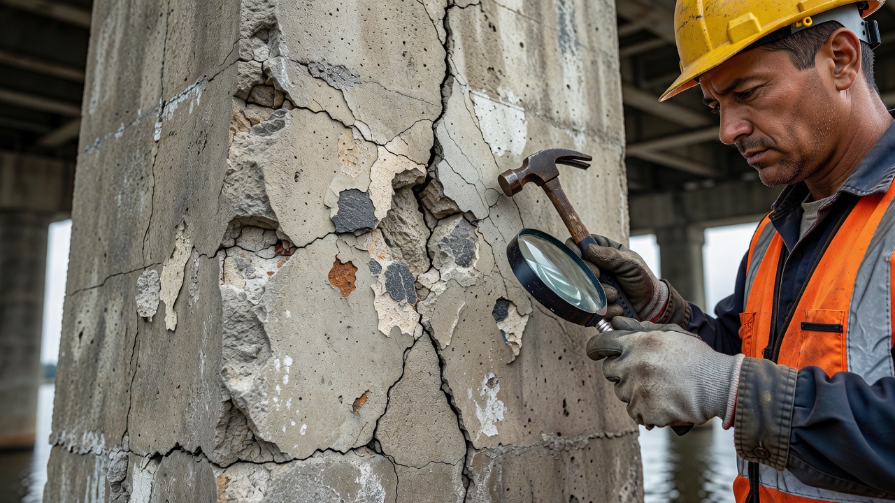
Spalling is the detachment of concrete surface layers due to internal stresses exceeding the tensile strength of the concrete. Spalling at piers is most commonly caused by:
Corrosion-induced spalling — reinforcement corrosion products (rust) occupy 2-6 times the volume of the original steel, generating tensile stresses of 1,000-3,000 psi in the surrounding concrete. This causes the concrete cover to delaminate and spall. Corrosion-induced spalling typically initiates at the column corners and along the line of the outermost reinforcement.
Freeze-thaw spalling — water in saturated concrete pores expands by 9% upon freezing, generating internal hydraulic pressure. After repeated freeze-thaw cycles (typically 300-500 cycles in moderate climates), the concrete surface deteriorates into a scaled, friable layer.
Collision spalling — localized concrete damage from vehicle or vessel impact. The impact area typically shows a crater-like spall with radiating cracks. Collision damage may expose or sever reinforcement.
The FHWA spalling classification:
Light: Spall depth less than 1 inch, area less than 6 inches in any dimension
Moderate: Spall depth 1-3 inches, area less than 12 inches in any dimension
Severe: Spall depth greater than 3 inches, area greater than 12 inches in any dimension, reinforcement exposed
Reinforcement Corrosion
Corrosion of steel reinforcement is the leading cause of deterioration in reinforced concrete piers. The corrosion mechanism is electrochemical, requiring oxygen, moisture, and an electrolyte (concrete pore water with dissolved chlorides).
Chloride-induced corrosion is initiated when the chloride concentration at the reinforcement depth exceeds the threshold value — approximately 0.15% by weight of cement for ASTM A615 carbon steel reinforcement. Chlorides penetrate through the concrete cover via diffusion, with the diffusion coefficient of concrete ranging from 1×10⁻¹² to 1×10⁻¹¹ m²/s for typical bridge concrete. The time to corrosion initiation (Ti) is modeled by Fick’s second law:
Ti = [d² / (4 × D × erf⁻¹(1 - Cth/Co))]²
where d is the cover depth, D is the chloride diffusion coefficient, Cth is the threshold concentration, and Co is the surface chloride concentration. In bridge piers exposed to deicing salts, Ti is typically 10-25 years for 2-inch cover concrete, increasing to 50-75 years for 3-inch cover.
Corrosion damage classification per BIRM:
Active corrosion: Rust staining visible on concrete surface, cracking pattern over reinforcement, local delamination
Section loss: Reinforcing bar diameter reduced by visible amount (up to 20%), measured by caliper after exposing the bar
Severe section loss: Greater than 20% diameter reduction, requiring structural evaluation per AASHTO
Corrosion repairs use half-cell potential mapping per ASTM C876 to identify active corrosion zones. Potentials more negative than -350 mV (vs. Cu/CuSO4) indicate a greater than 90% probability of active corrosion. Corrosion rate measurements by linear polarization resistance (LPR) provide quantitative corrosion current density data (icorr > 0.5 μA/cm² indicates moderate to high corrosion activity).
Collision Damage
Vehicular and vessel collision is a frequent cause of pier damage, particularly for piers located within the clear zone of roadways (typically 30 ft from edge of through lane) or in navigable waterways.
Vehicle collision on highway piers is addressed in AASHTO Section 3.6.5, which specifies an equivalent static load of 600 kips (2,670 kN) applied horizontally at 5 ft (1.5 m) above the ground line in any direction. The design impact length is 5 ft (1.5 m). Impact forces over 1,000 kips have been documented in heavy truck collisions at highway speeds.
Vessel collision loads on waterway piers are given in AASHTO Section 3.6.4. The equivalent static force depends on the vessel type, displacement, velocity, and impact angle. For a typical barge (1,000-2,000 tons) at 5-10 knots, the impact force ranges from 1,000 to 5,000 kips. The AASHTO vessel collision equation is:
PB = 0.98 × (DWT)⁰·⁵ × V × α
where DWT is the vessel deadweight tonnage, V is the velocity (ft/s), and α is the impact angle correction factor (1.0 for head-on collision).
Collision damage documentation includes:
Damage zone dimensions — height, width, and depth of impact crater
Reinforcement condition — exposed bars, cut bars, bent bars
Section loss — estimated reduction in column cross-section area
Residual capacity evaluation — reduced section analysis per AASHTO
Scour
Scour is the removal of streambed material around pier foundations by flowing water. Scour is the leading cause of bridge failures in the United States, accounting for approximately 60% of all bridge failures. FHWA documented 1,503 bridge failures between 1960 and 2020, with 946 attributed to hydraulic causes.
Three types of scour occur at piers:
Local scour — the horseshoe vortex system that forms at the pier base erodes a localized scour hole. The Colorado State University (CSU) pier scour equation, from HEC-18 5th Edition (2012), calculates the maximum local scour depth:
Contraction scour — the bridge opening constricts the flow, increasing the velocity and shear stress on the streambed. The Laursen equation (HEC-18 Chapter 6) computes contraction scour depth as a function of the discharge contraction ratio, the median bed material size (D50), and the approach flow conditions.
Degradation scour — long-term streambed elevation change due to changes in hydrology, upstream development, dam operations, or channel migration. Degradation is evaluated using stream gage records, historical cross-section surveys, and geomorphic assessment.
Scour-critical piers are identified in the NBIS scour screening process (23 CFR 650.313). The scour classification uses four categories:
Scour Susceptible — Pier foundations are vulnerable to scour based on geomorphic assessment
Scour Critical — Pier foundation has computed scour depth exceeding the foundation depth
Scour Analyzed — Scour analysis complete, foundation depth adequate
Scour Monitored — Scour is monitored during flood events using instrumentation
Settlement
Settlement is the downward movement of the pier due to compression of the foundation soil or rock. Settlement in piers can be:
Uniform settlement — all columns of the pier settle by the same amount. Uniform settlement of up to 1 inch (25 mm) is typically accommodated by the superstructure without significant distress. Settlement exceeding 3 inches (75 mm) may cause approach slab settlement and rideability issues.
Differential settlement — individual columns within a bent settle by different amounts, inducing torsional and flexural stresses in the cap beam. Differential settlement of 0.5 inch (12 mm) between adjacent columns can produce cap beam moments equivalent to 20-30% of the design live load moment.
Lateral spreading — horizontal displacement of the pier due to liquefaction of the foundation soil during seismic events. Lateral spreading of 6-12 inches has been documented in the 1989 Loma Prieta earthquake and 1994 Northridge earthquake at bridge pier locations.
FHWA SNBI Pier Rating
Under the Specifications for the National Bridge Inventory (SNBI), which replaced the NBI coding guide effective for inspections conducted after January 1, 2025, the pier is coded as a substructure element under data items B.SB.01 through B.SB.07.
B.SB.01 — Substructure Material identifies the material type for the pier:
1 — Reinforced concrete
2 — Prestressed concrete
3 — Steel
4 — Timber
5 — Masonry
6 — Aluminum, wrought iron, or cast iron
7 — Other
8 — Unknown
B.SB.02 — Substructure Type identifies the pier configuration:
1 — Solid wall pier
2 — Multi-column bent
3 — Hammerhead pier
4 — Single column pier
5 — Pile bent
6 — Pile encased in concrete
7 — Drilled shaft
8 — Other
9 — Unknown
B.SB.06 — Substructure Condition Rating uses a 0-9 scale where the rating is based on the severity and extent of observed defects:
Rating
Condition
Description
9
Excellent
No defects documented
8
Very Good
Minor cosmetic defects only, no structural impact
7
Good
Minor structural or functional deterioration, no significant section loss
6
Satisfactory
Moderate deterioration, no significant structural effect
5
Fair
Moderate section loss or cracking, structural capacity marginally adequate
4
Poor
Advanced section loss or deterioration, significant reduction in structural capacity
3
Serious
Severe section loss, structural capacity substantially reduced
2
Critical
Pier not capable of carrying design loads, advanced deterioration
1
Imminent Failure
Pier is in danger of collapse
0
Failed
Pier has collapsed
The SNBI rating methodology requires the inspector to evaluate each column of a multi-column bent separately and assign the overall pier rating based on the worst-rated individual component. This differs from the previous NBI Item 60 rating, which considered the substructure as a monolithic element.
Pier Inspection
Bridge pier inspection is conducted under NBIS requirements codified in 23 CFR 650.309-650.315. The standard inspection interval is 24 months, though underwater inspections may be deferred up to 72 months based on risk assessment per 23 CFR 650.311(b).
Visual Inspection
Visual inspection is the primary inspection method for piers. The inspector records defects on standardized forms per State DOT protocols, following BIRM defect documentation conventions.
The inspector evaluates:
All exposed surfaces of columns, cap beams, and footings
Bearing devices at the cap beam-girder interface
Joint seals between pier segments
Drainage features at the top of the pier
Water presence indicating leaks through joints or cracks
Vegetation growth on pier surfaces (roots can widen cracks)
Debris accumulation at the pier base
The BIRM requires the inspector to record for each defect:
Defect type (crack, spall, corrosion, etc.)
Severity (light, moderate, severe)
Extent (percentage of area affected)
Location (column number, height above base, face orientation)
Stability (active, dormant, progressing)
Photographs with scale reference
Hands-On Inspection
Hands-on inspection is required for critical defect evaluation and for underwater inspection. The following access methods are used:
Snooper trucks (under-bridge inspection units) — truck-mounted articulated booms that provide access to pier caps and column upper regions. Maximum reach typically 45-75 ft vertically and 30-50 ft horizontally. Inspection platforms must have 300 psi minimum fall protection per OSHA 1926.502.
Boat access — used for piers in waterways where the column extends above the water surface. Standard 16-22 ft jon boats or inflatable craft provide access for visual inspection of the splash zone (2-5 ft above and below the waterline).
Rope access (industrial rappelling) — certified rope access technicians per SPRAT or IRATA standards provide access to pier surfaces. Rope access is the most efficient method for tall piers (over 75 ft) where snooper truck reach is inadequate. The FHWA Bridge Inspection Team qualifications (23 CFR 650.309) require rope access inspectors to hold a minimum SPRAT Level I certification.
Scaffolding — tube-and-coupler or system scaffolding erected around the pier for detailed access. Used when extensive hands-on testing (cover meter, half-cell, coring) is required.
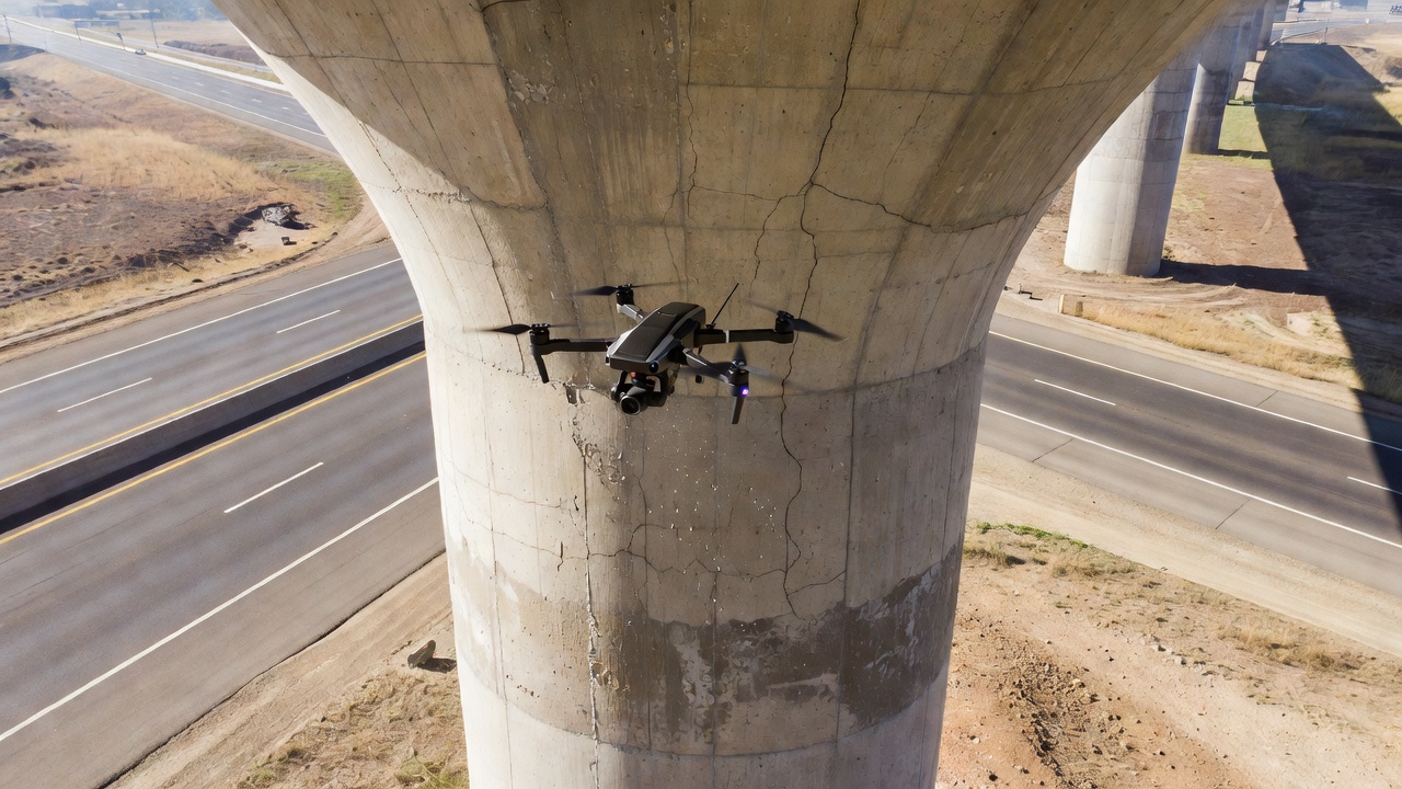
Drone Inspection
Unmanned Aerial Vehicles (UAVs) or drones are increasingly used for pier inspection, particularly for tall piers over 150 ft. The FHWA released the “Bridge Inspection with Unmanned Aerial Vehicles” guide (FHWA-HRT-23-011) in 2023, establishing operational protocols.
Drone inspection advantages:
No traffic disruption — drones operate without lane closures
Reduced personnel exposure — eliminates working at height hazards
High-resolution imagery — 20-60 MP cameras with 24-200 mm zoom lenses provide crack resolution down to 0.01 inches (0.25 mm)
GPS accuracy: RTK-enabled with 1-inch (2.5 cm) horizontal accuracy
Safety tether: Required for flights over water unless equipped with flotation
Data collection protocols require 85% overlap in both forward and lateral directions for photogrammetric 3D model reconstruction. Inspection flight speed should not exceed 3 ft/s (0.9 m/s) for crack detection missions.
Underwater Inspection
Underwater inspection of pier foundations follows the NHI Course 130078 “Underwater Bridge Inspection” manual and 23 CFR 650.311(c)(6). The inspection interval for underwater piers is determined by the Underwater Inspection Level:
Level I (Routine) — Visual inspection by diver, every 60 months minimum. Diver swims the full perimeter of each pier, documenting scour holes, debris accumulation, riprap condition, and exposed foundation elements.
Level II (Detailed) — Close visual inspection with cleaning (wire brush, water jet), every 36-72 months. The diver removes marine growth and probes for scour depth using a 0.5-inch diameter steel rod. Minimum diver qualification: Commercial Diver per ADCI standards plus NHI Underwater Bridge Inspection certification.
Level III (Advanced) — Non-destructive testing by diver (ultrasonic thickness measurement, cathodic potential measurement, acoustic imaging), every 12-36 months depending on defect progression.
Underwater inspection equipment includes:
Full-face dive mask with two-way communication
Underwater video camera (1080p minimum, 4K preferred) with lighting (4,000+ lumens)
Sounding rod — graduated 0.5-inch steel rod, 6-20 ft length
Tape measure and depth gauge
Slate or underwater tablet for data recording
The diver must document for each pier:
Scour depth — measured from the streambed to the original foundation elevation
Scour extent — horizontal dimensions of scour hole around the pier
Exposed foundation — type, material, condition of exposed surfaces
Debris accumulation — size, quantity, potential for additional damage
Scour Assessment at Piers
Scour assessment at piers follows the FHWA Hydraulic Engineering Circular No. 18 (HEC-18) procedures. The assessment is performed for each pier located in a waterway and involves computing the total scour depth from long-term degradation, contraction scour, and local scour contributions.
Hydrologic and Hydraulic Analysis
The hydraulic analysis computes the design discharge, water surface elevation, and flow velocity at each pier for the 100-year flood event (design flood) and the 500-year flood event (check flood). Methods include:
HEC-RAS (Hydrologic Engineering Center - River Analysis System) — 1D and 2D hydraulic modeling providing velocity and depth at each pier
Rational Method — for small watersheds (less than 100 acres)
USGS Regression Equations — regional equations for ungaged watersheds in each state
Scour Vulnerability Classification
Each pier is classified per the NBIS scour vulnerability process. Scour-critical piers require a Plan of Action (POA) per 23 CFR 650.313(j) that includes monitoring during flood events at 50% of the 100-year flow, post-flood inspection within 24 hours of the peak flow, and countermeasure design if monitoring indicates active scour.
Countermeasure Selection
Per FHWA HEC-23 5th Edition (2023), scour countermeasures at piers are classified as:
Armoring countermeasures — protect the streambed from hydraulic forces:
Riprap — loose stone placed around the pier, D50 determined by HEC-23 Design Guideline 11, minimum layer thickness 2×D50
Grout-filled bags — geotextile bags filled with grout, placed in a staggered pattern around the pier
Partially grouted riprap — conventional riprap with 40-60% void filling
River training countermeasures — modify the flow pattern to reduce pier loading:
Guide banks (spur dikes) — earth embankments with riprap armoring, extending upstream at 45° from the bridge approach
Upstream vanes — submerged vane structures that redirect flow away from the pier
Pier shape modification — adding nose extensions or splitter piers to streamline the hydraulic profile
Seismic Vulnerability
Pier seismic vulnerability is evaluated following the FHWA Seismic Retrofitting Manual for Highway Structures (FHWA-HRT-06-032) and AASHTO Guide Specifications for LRFD Seismic Bridge Design (2nd Edition, 2017).
Seismic Hazard Assessment
The seismic hazard at the pier location is defined by:
Peak ground acceleration (PGA) — from USGS seismic hazard maps, representing a 7% probability of exceedance in 75 years
Seismic Design Category (SDC) — A (minimal hazard) through D (extreme hazard) per AASHTO Table 3.10.3-1, based on the one-second period spectral acceleration (S1)
Pier Seismic Performance
Pier columns are designed for ductile seismic response. The plastic hinge mechanism must be controlled and detailed per AASHTO 4.11.6:
Plastic hinge zone: Extends a distance of 1.5×column diameter or 1.5×section depth from the connection (top and bottom)
Confinement reinforcement: Maximum spacing of 4 inches in the plastic hinge zone, minimum spiral pitch of 1 inch
Transverse reinforcement ratio: Minimum ρs = 0.004 to 0.006 in plastic hinge zones for circular columns
Strain limits: Maximum concrete compressive strain of 0.003 per AASHTO 5.7.2.1, though confined sections can reach 0.01-0.015
Seismic Retrofit Categories
FHWA-HRT-06-032 defines four Seismic Retrofit Categories for pier columns:
SRC A — Columns require no retrofit, minimum transverse reinforcement sufficient
SRC B — Minor retrofit required, typically column shear capacity enhancement
SRC C — Moderate retrofit required, column flexural and shear enhancement
SRC D — Major retrofit required, column replacement or comprehensive jacketing
Retrofit Techniques
Column retrofit techniques per FHWA-HRT-06-032:
Steel jacketing — welding 0.125-0.375 inch (3-9 mm) thick steel shells around existing columns and filling the annular gap (0.5-2 inches) with cementitious grout. Steel jackets provide confinement enhancement that increases concrete compressive strength by 30-60%, shear capacity increase, and ductility improvement with drift capacity increasing from 2% to 8% for circular columns.
Concrete jacketing — adding 4-12 inches of reinforced concrete around existing columns. The jacket must contain longitudinal bars (minimum 0.5% of jacket area), transverse ties at 6-12 inch spacing, and dowel connections drilled and epoxied into the existing column at 12-18 inch spacing.
FRP wrapping — bi-directional carbon fiber reinforced polymer (CFRP) or glass fiber reinforced polymer (GFRP) wraps applied in 1-4 layers. Per ACI 440.2R-17, the design confinement pressure provides a 40-80% increase in axial capacity and 100-200% increase in drift capacity for circular columns.
Repair and Strengthening
Pier repair and strengthening methods are selected based on the distress mode, severity, and desired performance improvement.
Concrete Spall Repair
Spall repair follows the procedures in ACI 546R-14 Guide to Concrete Repair:
Remove damaged concrete to sound substrate using chipping hammers (15 lb maximum) or hydro-demolition (10,000-20,000 psi water jet)
Prepare exposed reinforcement by abrasive blast to SSPC-SP10 (near-white metal) cleanliness
Apply corrosion inhibitor — calcium nitrite (2-4 gallons/yd³ in the repair mortar) or migrating corrosion inhibitors
Crack injection per ACI 224.1R is used for structural cracks wider than 0.004 inches (0.1 mm):
Epoxy injection: 40-200 psi injection pressure, low-viscosity epoxy (500-1,000 cP), restores 90-100% of original tensile strength
Polyurethane injection: Used for active water leakage, hydrophilic polyurethane expands 10-30× on contact with water
Injection port spacing: Equal to crack depth, typically 6-12 inches along the crack length
FRP Strengthening
FRP strengthening per ACI 440.2R-17 is used for flexural strengthening, shear strengthening, and confinement of columns. FRP system design parameters include:
Parameter
CFRP (High Strength)
GFRP
Tensile strength
350-550 ksi
80-150 ksi
Modulus of elasticity
25,000-33,000 ksi
5,000-8,000 ksi
Ultimate strain
1.2-1.7%
2.0-4.0%
Cured ply thickness
0.006-0.020 inches
0.020-0.060 inches
Application requires surface preparation to ICRI CSP-3 to CSP-5, temperature between 50-95°F during cure, and protection from UV if GFRP is used.
Cathodic Protection
Cathodic protection for pier reinforcement is applied per NACE SP0290. Sacrificial anode systems use zinc or magnesium anodes bonded to the reinforcement, providing 10-15 years of protection with a current density of 0.2-0.5 mA/ft² of steel surface. Impressed current systems use mixed metal oxide (MMO) titanium mesh anodes installed in a cementitious overlay (1-2 inches thick), powered by a rectifier providing 6-24V DC. Design current density is 0.5-2.0 mA/ft² of steel surface per NACE criteria.
Foundation Underpinning
Foundation underpinning is required when pier settlement or scour has compromised the foundation capacity. Pile underpinning involves driven piles installed adjacent to the existing footing with a minimum of 2 piles per corner. Micropile underpinning uses 5-12 inch diameter drilled and grouted piles with high-strength steel bar (75-100 ksi yield), with design capacities from 50 to 300 tons per pile. Jet grouting uses high-pressure (3,000-6,000 psi) grout injection to create soil-cement columns (3-8 ft diameter) beneath the existing footing.
Scour Repair
Scour repair at piers is classified as emergency or permanent. Emergency scour repair performed immediately after a flood event includes riprap dumping (12-36 inch stone), grout bag placement (1-3 ft³ bags), and sand bag placement for minor scour holes. Permanent scour countermeasures designed per HEC-23 for the 100-year flood event include riprap aprons (thickness of 2×D50, extending 2×pier width upstream), sheet pile cut-off walls driven around the pier perimeter (depth determined by computed scour depth plus 5 ft minimum), and anchor blocks connected to the pier by tie-rods.
Frequently Asked Questions
A bridge pier is an intermediate vertical support structure located between abutments that transfers loads from the bridge superstructure to the foundation. Unlike abutments, which support the bridge ends and retain the approach embankment, piers are freestanding intermediate supports. They can be made of reinforced concrete, steel, masonry, or timber, with reinforced concrete being the most common material in modern highway bridges.
The five main types of bridge piers are: (1) Solid wall piers — continuous vertical walls with or without openings; (2) Multi-column bent piers — two or more columns connected by a cap beam; (3) Hammerhead piers — single column flaring into a T-shaped cap; (4) Single column piers — isolated circular or rectangular columns; (5) Pile bent piers — driven piles extended above ground with a cap. Selection depends on span length, hydraulic conditions, seismic demands, and aesthetic requirements.
Bridge piers are inspected under the National Bridge Inspection Standards (NBIS) using visual inspection as the primary method, supplemented by hands-on inspection (snooper trucks, ladders, scaffolding), drone-based inspection for hard-to-reach areas, and underwater inspection for foundations below the waterline. Inspectors evaluate concrete cracking, spalling, corrosion of reinforcement, scour, settlement, collision damage, and bearing condition. The pier is rated under the SNBI substructure element coding system.
Pier scour is caused by the acceleration and turbulence of water flow around a pier obstructing the flow. Three types of scour occur at piers: (1) Local scour — horseshoe vortex and wake vortices that erode the streambed immediately around the pier; (2) Contraction scour — flow acceleration through the bridge opening causing general bed lowering; (3) Degradation scour — long-term streambed elevation change. The FHWA HEC-18 manual provides the Colorado State University (CSU) pier scour equation for estimating scour depth.
Pier repair and strengthening methods include: (1) Concrete repair — spall repair with patch materials, crack injection with epoxy; (2) Concrete jacketing — adding 4-12 inches of reinforced concrete around existing columns; (3) Steel jacketing — welding steel shells (0.125-0.375 inch thick) around columns for confinement; (4) FRP wrapping — carbon or glass fiber wraps for seismic confinement and corrosion protection; (5) Cathodic protection — impressed current or sacrificial anode systems to control rebar corrosion; (6) Scour countermeasures — riprap, grout bags, or sheet piling around foundations.
Under the Specifications for the National Bridge Inventory (SNBI), the pier is coded as a substructure element with data items B.SB.01 (substructure material), B.SB.02 (substructure type), B.SB.06 (condition rating). The condition rating uses a 0-9 scale where 9 is excellent condition and 0 is failed. The rating is based on the severity and extent of observed defects. The SNBI decouples the condition rating from the NBI Item 60 (substructure) system, providing element-level granularity.
Need bridge pier inspection expertise?
Our team provides comprehensive bridge pier assessments, condition ratings per SNBI standards, scour evaluation, and repair design services compliant with FHWA and AASHTO specifications.
Bridge Girder — Types, Inspection, and Distress Modes
Bridge girders are the primary horizontal load-carrying beams supporting the bridge deck, spanning between piers and abutments. Common types include steel I-gir...
An abutment is the end support structure of a bridge that retains the approach embankment, transfers superstructure loads to the foundation, and accommodates th...
Bridge bearings are critical load-transfer devices at abutments and piers that transmit superstructure forces to the substructure while accommodating thermal mo...
28 min read
Bridge components
Bridge inspection
+3
Cookie Consent We use cookies to enhance your browsing experience and analyze our traffic. See our privacy policy.