The plate bearing test (plate load test) applies static loads to a circular steel plate on the ground surface, measuring settlement to determine soil bearing capacity, modulus of subgrade reaction (k-value), and elastic modulus. It is used for pavement foundation evaluation, especially for airport and heavy-duty pavements.
Definition and Purpose
The plate bearing test, also known as plate load test, is an in-situ field test that determines the load-bearing capacity and deformation characteristics of soil and pavement foundations. The test involves applying a vertical static load through a rigid circular steel plate placed on the ground surface and precisely measuring the resulting settlement at each load increment. The fundamental principle is straightforward — the soil’s response to loading is measured directly where the structure will be built, eliminating reliance on laboratory assumptions or empirical correlations that may not capture actual field conditions.
The primary quantities derived from a plate bearing test are the ultimate bearing capacity of the soil (the maximum pressure the ground can sustain before shear failure), the allowable bearing capacity (the safe design pressure after applying a factor of safety, typically 3.0), the modulus of subgrade reaction (k-value) , and the elastic modulus (E) . These parameters are essential inputs for designing shallow foundations, rigid and flexible pavements, crane pads, working platforms for heavy construction equipment, and airfield pavements subjected to high wheel loads and tire pressures.
The plate bearing test is specified by several international standards. The two most widely used standards in the United States are ASTM D1195-21 (Standard Test Method for Repetitive Static Plate Load Tests of Soils and Flexible Pavement Components) and ASTM D1196-21 (Standard Test Method for Nonrepetitive Static Plate Load Tests of Soils and Flexible Pavement Components). The U.S. Army Corps of Engineers standard CRD-C 655-95 governs testing for military and many federal projects. In Europe, DIN 18134 (Plate Loading Test) is the governing standard, while the United Kingdom uses BS 1377-9:1990. For airport pavements, the Federal Aviation Administration (FAA) mandates plate bearing tests in its Advisory Circular AC 150/5320-6G for determining the modulus of subgrade reaction (k) for rigid pavement design at civil airports.
The plate bearing test is considered the gold standard for in-situ pavement foundation evaluation because it directly measures the stress-strain behavior of the soil under controlled loading conditions. Unlike laboratory tests that require undisturbed sampling and transportation, the plate test assesses the soil in its natural state, including effects of moisture content, density, fabric, and any existing compaction that would be destroyed during sampling and handling.
Equipment for Plate Bearing Test
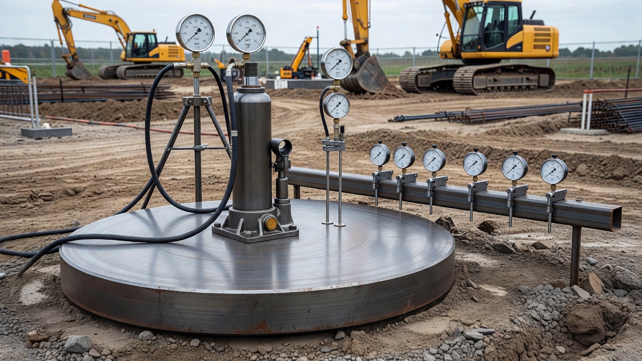
The plate bearing test requires a carefully assembled system of specialized equipment to apply controlled loads and measure minute settlements with high precision. Each component plays a critical role in obtaining accurate, repeatable results.
Bearing Plate
The bearing plate is the primary interface between the loading system and the soil. It is a thick, rigid circular steel plate with a minimum thickness of 25 mm (1 inch) , though plates of 30–50 mm thickness are common for heavy-duty testing. Standard diameters range from 300 mm (12 in) to 762 mm (30 in) , with the 762 mm plate being the standard reference size for FAA airport pavement design per AC 150/5320-6G. The plate must be sufficiently rigid to distribute the load uniformly across the full contact area without bending — any significant plate deflection would concentrate stress at the plate center and invalidate the assumption of uniform pressure distribution. Plates are typically equipped with centering marks and lifting handles for precise positioning in the test pit.
Research by Rushing (2024) at Mississippi State University demonstrated that plate size significantly affects the measured k-value, with smaller plates producing higher apparent stiffness values due to the shallower depth of influence. This plate-size effect necessitates correction factors when converting k-values obtained with non-standard plate diameters to the reference 762 mm plate.
Hydraulic Jack
The hydraulic jack generates the compressive force applied to the bearing plate. The jack must have sufficient capacity to load the soil to failure, typically 100 kN to 500 kN (approximately 10 to 50 tons), depending on soil strength and plate size. The jack is positioned concentrically on the bearing plate with a spherical seating to ensure purely vertical load application without eccentric moments. A calibrated pressure gauge or electronic pressure transducer measures the hydraulic pressure, which is converted to applied force using the jack’s calibration factor. Modern automated plate load test systems use servo-hydraulic actuators with electronic feedback control for precise load application at specified rates.
Reaction Frame
The reaction frame provides the counterforce against which the hydraulic jack pushes. This is the heaviest component of the test setup and must have a reaction capacity exceeding the maximum test load. Common reaction systems include:
Heavy truck or loaded trailer: A dump truck loaded with construction materials is positioned directly over the test plate, using its weight as reaction mass. This is the most common field setup due to its mobility and simplicity.
Steel reaction frame with kentledge: A purpose-built steel beam or frame anchored by concrete blocks or steel weights (kentledge). This setup is used when truck access is limited or when testing in confined areas.
Ground anchors: Steel rods drilled into the ground and tensioned to provide reaction. This method avoids the need for heavy surface weights but requires anchor installation.
Automated plate load test (APLT) systems: Self-contained units like the InGios APLT provide their own reaction mass (7–15 tons) with integrated hydraulic, electronic, and data acquisition systems.
The reaction system must be positioned to avoid influencing the test area. A minimum clearance of 1.5 times the plate diameter between the reaction supports and the plate edge is required per ASTM standards to prevent the reaction forces from artificially confining the soil beneath the test plate.
Dial Gauges and Settlement Measurement
Settlement measurement requires dial gauges or linear variable differential transformers (LVDTs) with a precision of 0.01 mm (0.0005 in) and a travel range of 50 mm (2 in) minimum. Typically, two to four gauges are mounted symmetrically around the plate on a reference beam that is independent of the loading system. The reference beam is supported on firm ground at a distance of at least 1 meter from the test plate, ensuring that the gauges measure only soil settlement, not equipment deflection or ground disturbance from the reaction system.
The gauges bear on the plate surface through a crossbeam or directly on the plate edge. For repetitive (cyclic) tests per ASTM D1195, continuous electronic displacement transducers record dynamic settlement under each load cycle, capturing elastic (recoverable) and plastic (permanent) deformation components. Modern digital systems record data at sampling rates of 100 Hz or higher for detailed load-settlement analysis.
Supporting Equipment
Additional equipment includes a load cell or proving ring for direct force measurement (as a check on hydraulic pressure readings), a seating load system for applying an initial contact pressure, a spirit level for plate alignment, sand for bedding the plate to achieve full contact, a stopwatch for timing load increments, and data recording sheets or electronic data loggers. For cyclic testing, a load cycle counter and automated loading sequence controller are required.
Test Procedure (ASTM D1195 and ASTM D1196)
The plate bearing test procedure follows a carefully standardized sequence to ensure repeatability and comparability of results across different sites and operators. The two ASTM standards differ primarily in loading protocol — ASTM D1196 (nonrepetitive) is used for determining the static load-settlement relationship and ultimate bearing capacity, while ASTM D1195 (repetitive) applies multiple load cycles to measure resilient modulus and characterize elastic behavior under simulated traffic loading.
Site Preparation and Pit Excavation
A test pit is excavated to the elevation of the proposed foundation or pavement subgrade surface. The pit dimensions must be at least 4 to 5 times the plate diameter in width to avoid confinement effects from the pit walls. The bottom surface is carefully leveled and all loose material is removed. For tests on pavement layers, the overlying pavement structure is removed to expose the layer being tested — the subgrade surface for subgrade tests, or the base course surface for base evaluation.
A thin layer of fine sand (typically 2–5 mm thick) is placed and screeded level to provide a uniform bearing surface for the steel plate. The plate is positioned centrally in the pit and checked for levelness in both directions using a sensitive spirit level. Any gaps between the plate and the sand bed are carefully filled to ensure full contact across the entire plate area.
Seating Load
Before the main loading sequence, a seating load of approximately 7 kPa (0.15 ksf) per ASTM D1196 or 1% of the estimated ultimate load is applied and maintained for 1 minute, then released. This initial loading cycle seats the plate into the sand bed, closes any gaps, and establishes a stable reference datum for subsequent settlement measurements. After unloading, the gauges are zeroed and the test commences.
Loading Sequence — ASTM D1196 (Nonrepetitive)
Under ASTM D1196, the load is applied in increments of approximately 7 kPa (0.15 ksf) or 10% of the estimated ultimate bearing capacity, whichever is smaller. Each load increment is maintained until the settlement rate does not exceed 0.01 mm per minute for three consecutive minutes (the “stabilization criterion”). Settlement readings are recorded at 1-minute intervals during each load increment. The loading continues until one of three termination criteria is met: (1) the soil fails in shear (sudden and rapid settlement increase), (2) the total settlement reaches 25 mm (1 in) , or (3) the maximum planned test load (typically 1.5 to 2 times the design load) is achieved.
After reaching the maximum load, unloading is performed in decrements of approximately 25% of the maximum load, with each decrement held until settlement stabilizes. The rebound (recoverable settlement) during unloading provides information on the elastic properties of the soil.
Loading Sequence — ASTM D1195 (Repetitive)
Under ASTM D1195, a conditioning phase of 100 to 1,000 load cycles is first applied at a moderate stress level to seat the plate and stabilize the system. Then, the load is applied in repeated cycles at progressively increasing peak stress levels. Each cycle consists of loading to the target stress, holding for 0.1 to 1.0 seconds (simulating traffic pulse duration), unloading to a reduced seating stress (typically 10% of peak), and repeating. The recoverable (elastic) deflection at each cycle is recorded, and the permanent (plastic) deformation accumulated over cycles is tracked.
The standard specifies that for each stress level, the test proceeds until the recoverable deflection stabilizes (typically 50 to 200 cycles). The resilient modulus (Mr) at each stress level is calculated from the stabilized recoverable deflection using Boussinesq’s theory. This cyclic protocol simulates the repeated loading from aircraft or vehicle traffic and provides design parameters directly applicable to mechanistic-empirical pavement design methods.
Data Recording
Complete data recorded for each test includes: test location and number, date, weather conditions, soil type and description, plate diameter and thickness, sand bed condition, initial and final moisture content, density of the tested soil, load increment number, applied load and pressure, settlement at each gauge position at 1-minute intervals, time to stabilization at each increment, maximum load and final settlement, and unloading rebound data. Electronic data loggers provide continuous time-settlement records that capture soil creep behavior during each load increment.
Modulus of Subgrade Reaction (k-value) Calculation
The modulus of subgrade reaction (k) is one of the most important outputs of the plate bearing test, and it is the fundamental input parameter for rigid pavement design using the Westergaard or finite element methods employed by FAA, AASHTO, and other design agencies.
Definition of k-value
The modulus of subgrade reaction is defined as the ratio of the applied uniform pressure (p) to the corresponding settlement (δ) under a rigid circular plate:
k = p / δ
where:
k = modulus of subgrade reaction [MPa/m, pci, or MN/m³]
p = applied uniform pressure [MPa or psi]
δ = settlement of the bearing plate [m or in]
The k-value represents a spring constant per unit area of the soil foundation. It is not an intrinsic soil property but rather an engineering index parameter that depends on soil type, density, moisture content, plate size, stress level, and loading rate. For pavement design, the k-value describes the support provided by the subgrade to the pavement structure.
Reference Plate Size
Standard k-values are defined using a 762 mm (30 in) diameter circular plate per FAA and AASHTO specifications. When plates of different diameters are used, correction factors must be applied to convert the measured k-value to the equivalent 762 mm plate k-value. The conversion relationship is:
where n is an empirical exponent ranging from 0.5 to 0.8 depending on soil type. The FAA AC 150/5320-6G provides specific correction curves for different plate sizes.
k-value from Load-Settlement Curve
The k-value is determined from the linear portion of the load-settlement curve, typically between a seating pressure of 7 kPa (0.15 ksf) and a working pressure corresponding to the design load. The settlement at the design pressure is read from the curve, and k is calculated as described above. For FAA airport pavement design, the k-value is taken at a pressure of 0.069 MPa (10 psi) for rigid pavement evaluation, corresponding to typical tire contact pressures of aircraft gear.
The k-value obtained from a plate test represents the composite subgrade reaction at the surface. If the subgrade consists of multiple layers (e.g., a compacted subgrade over weaker natural soil), the composite k-value reflects the integrated response of all layers within the depth of influence (approximately twice the plate diameter, or 1.5 m for a 762 mm plate).
Factors Affecting k-value
Soil type has the most significant effect on k-value. Typical ranges are: soft clay — 5 to 15 MPa/m (20 to 55 pci), medium clay — 15 to 30 MPa/m (55 to 110 pci), stiff clay — 30 to 60 MPa/m (110 to 220 pci), sand — 20 to 40 MPa/m (75 to 150 pci), gravel — 40 to 80 MPa/m (150 to 300 pci), and cemented or stabilized materials — 80 to 200 MPa/m (300 to 750 pci). Moisture content significantly affects k-values for fine-grained soils, with saturation potentially reducing k by 50% or more. Density and compaction level directly control k-value for granular materials. Depth to rigid layer (bedrock or stiff stratum) increases k-value as the compressible soil layer thickness decreases.
Elastic Modulus from Plate Test
The elastic modulus (E) of the soil, also referred to as the Young’s modulus or deformation modulus, can be determined from plate bearing test results using the theory of elasticity. This parameter is essential for flexible pavement design using layered elastic analysis (e.g., FAA’s FAARFIELD software and AASHTOWare Pavement ME Design).
Boussinesq’s Solution for Plate Loading
For a rigid circular plate of radius a loaded on a homogeneous, isotropic, elastic half-space, the relationship between load, settlement, and elastic modulus is given by Boussinesq’s equation:
E = (q × a × (1 - ν²) × I_r) / δ
where:
E = elastic modulus [MPa]
q = applied uniform pressure [MPa]
a = radius of the bearing plate [m]
ν = Poisson’s ratio of the soil (typically 0.3 to 0.5)
I_r = rigidity factor (1.0 for a perfectly flexible plate, π/4 ≈ 0.785 for a rigid plate with uniform displacement)
δ = settlement of the plate [m]
For a rigid plate with uniform displacement (as used in standard plate bearing tests), the equation simplifies to:
E = (q × a × (1 - ν²) × π) / (4 × δ)
Initial Tangent Modulus vs. Secant Modulus
The load-settlement curve from a plate bearing test is typically nonlinear. The initial tangent modulus is calculated from the initial linear portion of the curve (very small strains, typically less than 0.1% strain). The secant modulus is calculated at a specific stress level corresponding to the design load (typically 50% of the ultimate bearing capacity or at a stress corresponding to the design tire pressure). For pavement design, the secant modulus at the expected working stress level is more relevant because it captures the soil stiffness at the stress conditions that will actually occur in service.
Resilient Modulus from Cyclic Testing
The resilient modulus (Mr) determined from cyclic plate bearing tests per ASTM D1195 is the most direct measure of pavement subgrade stiffness for mechanistic-empirical design. It is calculated from the recoverable (resilient) deflection under repeated loading:
where δ_resilient is the elastic rebound per load cycle after stabilization (typically after 50 to 200 conditioning cycles). The resilient modulus accounts for the fact that pavement materials respond elastically under repeated traffic loading after an initial period of permanent deformation accumulation.
Research using the Automated Plate Load Test (APLT) system (InGios Geotechnics) has demonstrated that cyclic plate testing with confining stress control can directly measure Mr values comparable to those obtained from laboratory triaxial testing (AASHTO T307), eliminating the need for undisturbed sampling and expensive triaxial equipment. The APLT applies up to 100,000 load cycles with programmable stress sequences to characterize the stress-dependent behavior of subgrade and base materials.
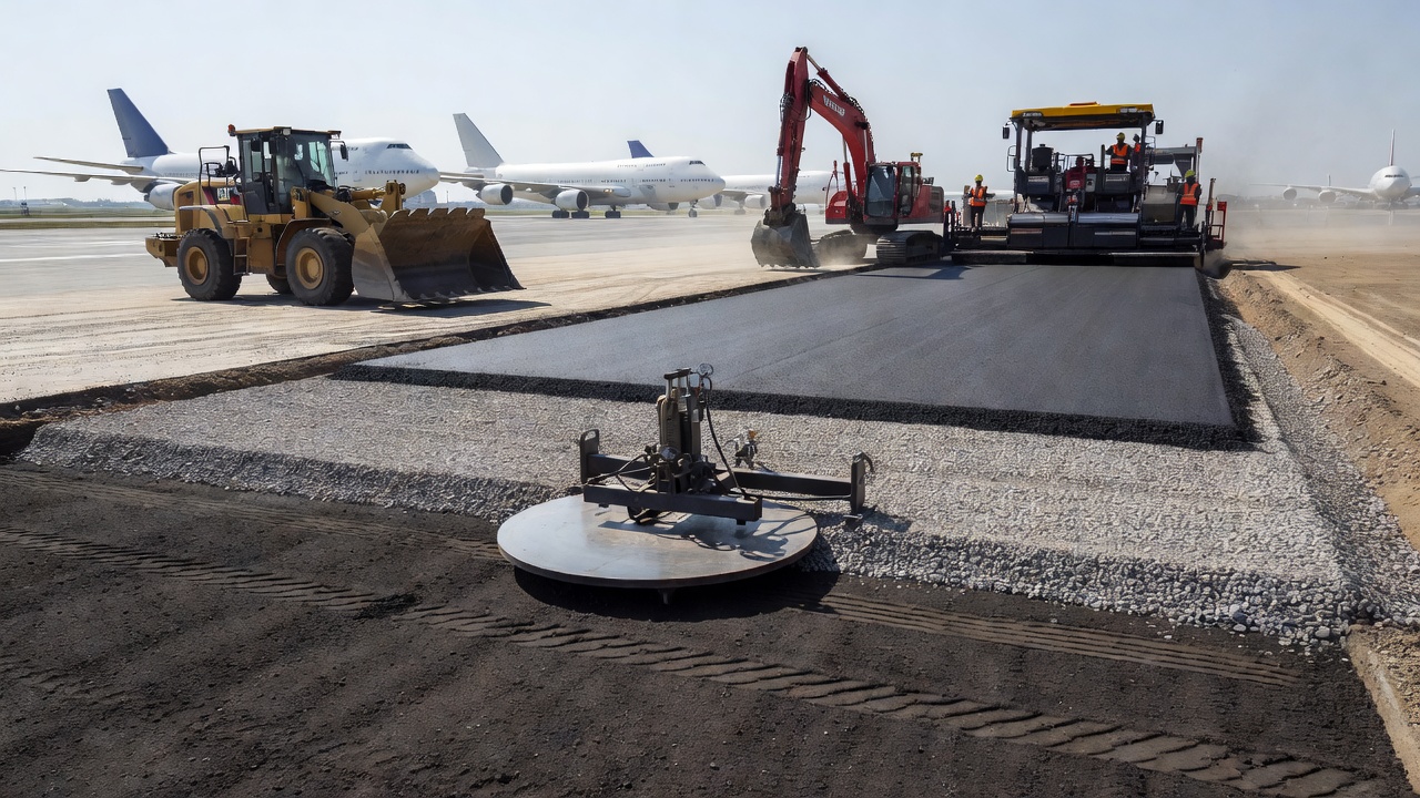
Plate Test for Airport Pavement Design
The plate bearing test is the cornerstone of rigid airport pavement design as specified by the FAA in Advisory Circular AC 150/5320-6G (Airport Pavement Design and Evaluation, June 2021). The FAA requires the modulus of subgrade reaction (k-value) as the primary subgrade input parameter for designing rigid pavement thickness using the FAARFIELD computer program.
FAA Design Methodology
The FAA’s rigid pavement design procedure in FAARFIELD is based on three-dimensional finite element analysis calibrated with full-scale tests at the National Airport Pavement Test Facility (NAPTF) in Atlantic City, New Jersey. The k-value from plate bearing tests directly controls the computed slab stresses and deflections, which determine the required Portland cement concrete (PCC) slab thickness.
Per FAA AC 150/5320-6G Section 2.3.9.12, the plate bearing test for airport pavements must use a 762 mm (30 in) diameter plate with the non-repetitive loading procedure (analogous to ASTM D1196). The test is performed on the prepared subgrade at the moisture content and density specified for construction. If the subgrade is treated or stabilized, the k-value is measured on the stabilized layer. The FAA specifies that at least one plate bearing test per 500 cubic meters (650 cubic yards) of subgrade material should be performed, with a minimum of three tests per project.
Seasonal Correction Factors
Because subgrade stiffness varies significantly with moisture content and frost conditions, the FAA requires application of seasonal correction factors to the measured k-values. For rigid pavement design, the weighted average annual k-value is computed considering the duration of each season (wet, dry, frozen, thaw) and the corresponding subgrade stiffness during each period. FAA AC 150/5320-6G provides guidance for estimating seasonal k-value variations based on soil type, climate region, and drainage conditions.
ICAO Requirements
The International Civil Aviation Organization (ICAO) references plate bearing test procedures in its Aerodrome Design Manual and through the Aircraft Classification Rating / Pavement Classification Rating (ACR-PCR) method for reporting pavement strength. ICAO Annex 14 (Aerodromes) requires that pavement bearing strength be reported using the ACR-PCR method, which relies on the subgrade strength category (High, Medium, Low, or Ultra Low) corresponding to specific k-value ranges:
ICAO Subgrade Category
k-value Range (MPa/m)
k-value Range (pci)
High
> 120
> 440
Medium
60–120
220–440
Low
25–60
90–220
Ultra Low
< 25
< 90
These categories are used for the standardized reporting of pavement strength in the ICAO ACR-PCR system, which replaced the older ACN/PCN method.
Heavy-Duty Pavements
For heavy-duty pavements serving large aircraft (Code E and F, such as the Boeing 777, 787, and Airbus A380), plate bearing tests are essential because the high tire pressures (up to 1.5 MPa / 220 psi for some aircraft) and heavy wheel loads (up to 300 kN / 67,000 lbs per wheel) require precise subgrade stiffness characterization to optimize pavement thickness. Underestimating k-value by even 20% can lead to over-designed pavements costing millions of dollars; overestimating k-value risks premature pavement failure and costly rehabilitation.
Plate Test vs CBR vs FWD
The plate bearing test is one of several methods for evaluating the strength and stiffness of pavement foundations. Understanding the differences between the plate test, California Bearing Ratio (CBR) test, and Falling Weight Deflectometer (FWD) is essential for selecting the appropriate test method for a given application.
Plate Bearing Test vs. CBR Test
The CBR test (California Bearing Ratio, described in ASTM D1883 and AASHTO T193) measures the penetration resistance of a soil by forcing a 50 mm (2 in) diameter plunger into the soil at a constant rate of 1 mm/min. The result is expressed as a percentage — the ratio of the load required to penetrate the test soil to the load required to penetrate a standard crushed rock material at the same penetration depth (typically 2.5 mm or 5.0 mm).
The plate bearing test fundamentally differs from CBR testing in several critical aspects: load application — plate tests apply a static load over a large area (up to 0.46 m² for a 762 mm plate) while CBR uses a small plunger (1,960 mm²); measured parameters — plate tests directly determine bearing capacity (kPa or MPa) and modulus (MPa), while CBR yields a dimensionless percentage ratio; applicability — plate tests are suitable for coarse-grained materials, crushed rock, engineered fills, and soils with large particles, while CBR is best for fine-grained soils with particles ≤20 mm; depth of influence — plate tests evaluate soil to a depth of approximately twice the plate diameter (up to 1.5 m), while CBR’s influence zone is limited to approximately 50–100 mm beneath the plunger.
The key advantage of plate testing over CBR for pavement design is that plate tests provide direct stiffness measurements (k-value and elastic modulus) that can be used directly in mechanistic design procedures (FAARFIELD, AASHTOWare, MePAD). CBR values must be converted to modulus using empirical correlations (e.g., Mr = 10 × CBR for fine-grained soils, or Mr = 17.6 × CBR^0.64 for granular materials), which introduce significant uncertainty — typically ±50% or more. The plate test eliminates this conversion uncertainty.
However, CBR testing has advantages in simplicity, cost, and speed. A laboratory CBR test can be completed in hours using relatively inexpensive equipment, while plate bearing tests require heavy field equipment, trained operators, and typically 3–6 hours per test. For highway design projects where thousands of tests are needed or where materials consist of fine-grained soils, CBR remains the practical standard.
Plate Bearing Test vs. Falling Weight Deflectometer (FWD)
The Falling Weight Deflectometer (FWD) is a dynamic nondestructive test device that applies an impulse load (typically 40–240 kN) to the pavement surface by dropping a mass from a controlled height onto a circular load plate. The resulting pavement surface deflections are measured by a series of geophone sensors (typically 7–9 sensors) positioned at radial distances from the load center, and the measured deflection basin is analyzed using backcalculation software to determine layer moduli.
Compared to plate bearing tests, FWD offers significant speed advantages: an FWD test takes approximately 60 seconds per point, allowing 50–100 tests per day compared to 3–6 tests per day for plate bearing tests. The FWD also evaluates the entire pavement structure (surface, base, subbase, and subgrade) rather than just the surface being tested. FWD testing is nondestructive, requiring no excavation or disturbance to the pavement.
However, the plate bearing test provides direct measurement of subgrade parameters under static loading conditions that more closely simulate the behavior of rigid pavement slabs under aircraft or vehicle loading. The FWD measures dynamic response at very short load durations (25–30 milliseconds), requiring backcalculation analysis and modulus conversion to obtain static-equivalent parameters for design. Plate tests also allow direct measurement of permanent deformation and accumulated plastic strain under repeated loading, which is critical for assessing long-term pavement performance.
Plate Bearing Test vs. Light Weight Deflectometer (LWD)
The Light Weight Deflectometer (LWD) is a portable, hand-operated dynamic plate test device that applies a smaller impulse load (typically 10–20 kN) through a 300 mm diameter plate. LWDs are widely used for quality control of compaction during construction because of their portability (total weight 15–25 kg) and rapid test cycle (1–2 minutes per test). The LWD measures the dynamic modulus (Evd) using a similar principle to the FWD but at smaller scale.
The LWD is complementary to the plate bearing test — LWD is best suited for rapid compaction control and material acceptance testing during construction, while the plate bearing test is the definitive method for design parameter determination and forensic investigation. LWD results from a 300 mm plate cannot be directly equated to k-values from a 762 mm plate bearing test without correction factors accounting for plate size effects, stress level differences, and loading rate (dynamic vs. static).
Plate Test Limitations
While the plate bearing test is the gold standard for pavement foundation evaluation, it has well-recognized limitations that must be considered when interpreting results and designing foundations.
Depth of Influence
The most fundamental limitation is the limited depth of influence, sometimes called the pressure bulb or stress bulb effect. For a circular plate loaded on a homogeneous half-space, the vertical stress distribution follows Boussinesq’s theory — at a depth of one plate diameter below the surface, the vertical stress is approximately 33% of the surface pressure; at two plate diameters depth, it is approximately 10% of the surface pressure. Consequently, the plate bearing test primarily characterizes the soil within a depth of approximately 1.5 to 2.0 times the plate diameter — for a 762 mm plate, this is about 1.1 to 1.5 meters.
This limitation means that plate tests cannot detect weaker soil layers at depths greater than 1.5 meters below the test surface. If a weak layer exists at 2–3 meters depth, the plate test will not capture its influence on foundation performance, potentially leading to unsafe design assumptions. Conversely, a strong surface crust overlying a weak deeper soil may produce misleadingly high k-values. To address this limitation, test pits are excavated to the actual foundation depth, and for stratified soils, plate tests should be performed on each distinct layer or combined with deeper borings and laboratory testing.
Plate Size Effects
The plate size effect introduces systematic differences between measured and design k-values. Because the k-value is defined for a specific plate diameter (762 mm per FAA standards), tests conducted with smaller plates produce different apparent stiffness values. Research at Mississippi State University (Rushing, 2024) and the U.S. Army Engineer Research and Development Center has shown that:
A 300 mm plate typically yields k-values 1.5 to 2.5 times higher than a 762 mm plate on the same soil.
The ratio decreases as soil stiffness increases (smaller difference in stiff soils).
Correction factors from the literature have wide variability (±30%).
The CRD-C 655-95 protocol (military standard) systematically produces lower k-values than the ASTM D1196 protocol on the same soils, complicating comparison of results from different standards.
Reaction Load Requirements
The requirement for a heavy reaction mass (typically 10–50 tons) to counteract the applied load creates logistical challenges. In confined spaces, on slopes, or on weak ground, positioning a loaded truck or reaction frame may be impractical. The reaction system itself may disturb the soil around the test area, particularly on soft ground where the reaction supports can cause bearing capacity failure before the test begins.
Point-Specific Results
Plate bearing tests evaluate soil at a single point. On heterogeneous sites where soil properties vary significantly over short distances, a few plate tests may not capture the full range of conditions. The FAA requirement of one test per 500 cubic meters of material assumes relatively uniform subgrade conditions; on variable sites with lenses, pockets, or transitions between soil types, much higher testing density may be needed.
Stress Path and Loading Rate Effects
The static loading applied during plate tests does not perfectly simulate the dynamic, transient loading from moving vehicles or aircraft. Traffic loads are applied in milliseconds, while plate test load increments are held for minutes. For fine-grained soils, this loading rate difference can significantly affect measured stiffness — clays tested at slow rates may creep and show higher settlement (lower stiffness) than under rapid traffic loading. This limitation is addressed through cyclic plate tests (ASTM D1195) that apply traffic-simulating load pulses.
Cyclic Plate Test
The cyclic plate bearing test, also known as the repetitive static plate load test, differs fundamentally from the standard non-repetitive test by applying the load in repeated cycles rather than as a single monotonic increase. This test method, described in ASTM D1195 and AASHTO T221, was developed specifically for pavement foundation evaluation because it simulates the repeated nature of traffic loading more realistically than a static test.
Purpose and Applications
The primary purpose of cyclic plate testing is to determine the resilient modulus (Mr) of subgrade soils and pavement foundation layers. The resilient modulus represents the elastic stiffness of the material after stabilization under repeated loading, which is the fundamental input parameter for the Mechanistic-Empirical Pavement Design Guide (MEPDG) and the AASHTOWare Pavement ME Design software. Cyclic testing also quantifies the permanent deformation (plastic strain) that accumulates under each load cycle, providing critical data for predicting rutting and long-term pavement performance.
Test Protocol
The cyclic plate test protocol per ASTM D1195 involves several distinct phases:
Phase 1 — Conditioning: 100 to 1,000 load cycles are applied at a moderate stress level (typically 30–50% of the estimated design stress) to seat the plate stabilize the system, and achieve a “shakedown” condition where the permanent deformation per cycle becomes approximately constant.
Phase 2 — Stress-Dependent Testing: The cyclic load is applied at increasing peak stress levels (typically 5 to 8 stress sequences), each consisting of 50 to 200 cycles. At each stress level, the recoverable (resilient) deflection and permanent deformation are recorded after stabilization. The resilient modulus at each stress level is calculated from the stabilized recoverable deflection.
Phase 3 — Confining Stress Characterization: For the most advanced cyclic testing using systems like the APLT, the confining stress applied to the test material is varied (using the reaction system to apply lateral confinement) to characterize the full stress-dependent resilient modulus behavior. This produces the k1, k2, k3 parameters of the universal resilient modulus constitutive model used in AASHTOWare Pavement ME Design.
Advantages Over Static Testing
Cyclic plate testing provides critical information that static testing cannot capture. It measures the elastic and plastic components of deformation separately, simulates the actual loading condition (repeated traffic loads), quantifies permanent deformation accumulation over thousands of cycles (assessing long-term performance), and determines stress-dependent stiffness (materials stiffen or soften depending on stress level). The APLT system from InGios Geotechnics can perform up to 100,000 load cycles per test with fully automated control, providing laboratory-quality resilient modulus data in the field.
Use in Forensic Investigation
The plate bearing test is an invaluable tool for forensic pavement investigation — the process of determining why an existing pavement has failed or is underperforming, and evaluating whether it can be rehabilitated or must be reconstructed.
Identifying Weak Subgrade Areas
When a pavement exhibits localized distress such as excessive rutting, cracking, or settlement in specific areas, plate bearing tests can identify whether the cause is weak subgrade support. Comparative testing between distressed and non-distressed areas quantifies the difference in subgrade stiffness. A section with a k-value of 20 MPa/m in a pavement designed for 50 MPa/m would explain inadequate performance and guide the rehabilitation strategy.
Evaluating Layer Contribution
By performing plate bearing tests at different stages of pavement removal — on the pavement surface, on the exposed base course after milling the asphalt, on the subbase, and on the subgrade — forensic investigators can determine the contribution of each layer to overall pavement stiffness. This layer-by-layer assessment helps differentiate between problems caused by subgrade weakness, base degradation, or surface layer failure.
Quality Control for Rehabilitation
When a failed pavement is being rehabilitated with an overlay or reconstruction, plate bearing tests on the prepared foundation confirm that the subgrade meets the design k-value before placing new pavement layers. This is particularly important for rubbleization or crack-and-seat projects where existing rigid pavements are broken and used as a base for flexible overlays — plate tests on the broken concrete verify adequate support for the asphalt overlay.
Monitoring Moisture-Induced Deterioration
Repeated plate bearing tests at the same locations over time can track seasonal changes in subgrade support caused by moisture infiltration, frost heave, or drainage problems. In forensic investigations of pavement failures related to poor drainage, plate tests during wet and dry seasons can quantify the reduction in subgrade stiffness (often 50–70% loss when subgrade is saturated), providing objective data to justify drainage improvement projects.
Correlation with Other Testing
In forensic investigations, plate bearing test results are typically correlated with other data sources — Dynamic Cone Penetrometer (DCP) indexes, Ground Penetrating Radar (GPR) layer thickness data, laboratory CBR and triaxial tests, and Falling Weight Deflectometer (FWD) deflection basin parameters. The plate test provides the absolute stiffness baseline against which rapid testing methods (DCP, FWD) are calibrated, enabling more efficient condition assessment of large pavement networks while maintaining the accuracy of the static plate reference.
Summary
The plate bearing test remains the definitive field method for determining the bearing capacity and stiffness of pavement foundations. Its direct measurement of load-settlement behavior under controlled conditions provides essential design parameters — ultimate and allowable bearing capacity, modulus of subgrade reaction (k-value), and elastic/resilient modulus — that form the foundation of pavement design to FAA, AASHTO, and international standards. While the test has limitations in depth of influence, plate size effects, and logistical requirements, its unmatched directness and accuracy make it indispensable for major airport and highway projects where foundation performance is critical. The emerging Automated Plate Load Test (APLT) technology promises to overcome traditional barriers of time and cost by enabling rapid, automated cyclic testing with laboratory-quality data collection directly in the field, extending the utility of plate bearing testing for routine quality assurance and mechanistic pavement design.
Frequently Asked Questions
ASTM D1195 covers repetitive static plate load tests where the load is applied in repeated cycles to measure both elastic and plastic deformation, making it suitable for determining resilient modulus. ASTM D1196 covers non-repetitive static plate load tests where the load is applied incrementally and held until settlement stabilizes, primarily used for determining the modulus of subgrade reaction (k-value) and ultimate bearing capacity.
Standard plate diameters range from 300 mm to 762 mm (12 to 30 inches). The most common sizes are 300 mm (12 in), 600 mm (24 in), and 762 mm (30 in). The plate size directly affects the depth of influence, which is approximately twice the plate diameter. Larger plates test deeper soil layers and should match the size of the actual footing or tire contact area being simulated.
The modulus of subgrade reaction k is calculated as k = p / δ, where p is the applied pressure (stress) on the bearing plate and δ is the corresponding settlement. For a 762 mm (30 in) diameter plate, the k-value is typically reported in units of MPa/m or pci (pounds per cubic inch). Correction factors are applied to adjust for plate size when using different diameter plates.
The plate bearing test applies a static load through a large circular steel plate (300-762 mm diameter) and measures settlement, determining bearing capacity and modulus of subgrade reaction. The CBR (California Bearing Ratio) test uses a small 50 mm diameter plunger pushed at a constant rate into the soil and is expressed as a percentage ratio. Plate tests are better for coarse materials and foundations, while CBR tests are suited for fine-grained soils and highway pavement design.
The main limitations are: (1) limited depth of influence (approximately twice the plate diameter), so it only tests near-surface soils; (2) results represent only the point of testing, not the entire site; (3) requires heavy reaction loads for setup; (4) can be time-consuming compared to dynamic tests like FWD; (5) plate size effects require correction factors for k-value interpretation; and (6) it does not directly measure soil properties at depth.
Need Geotechnical Testing for Your Pavement Project?
Our team provides expert plate bearing testing, subgrade evaluation, and pavement foundation assessment services to ensure your airport or highway pavement meets all design and safety requirements. Contact us for reliable field testing solutions.
The Falling Weight Deflectometer (FWD) is a non-destructive pavement testing device that drops a known impulse load onto a loading plate, measuring surface defl...
FWD deflection data analysis processes the measured deflection basin from FWD testing to back-calculate the elastic modulus of each pavement layer (HMA, base, s...
Pavement strength in airport infrastructure refers to the measured load-bearing capacity of paved surfaces such as runways, taxiways, and aprons, ensuring they ...
11 min read
Airport engineering
Runway design
+3
Cookie Consent We use cookies to enhance your browsing experience and analyze our traffic. See our privacy policy.