A PT duct is a sheath or conduit encasing post-tensioning tendons in concrete, creating a void for tendon movement during stressing and providing a path for protective grout injection. Duct types include corrugated metal, smooth plastic, and flat oval ducts. Grout quality, water ingress, and corrosion detection are critical for tendon durability.
Post-Tensioning Duct (PT Duct) in Concrete Structures
Definition and Function
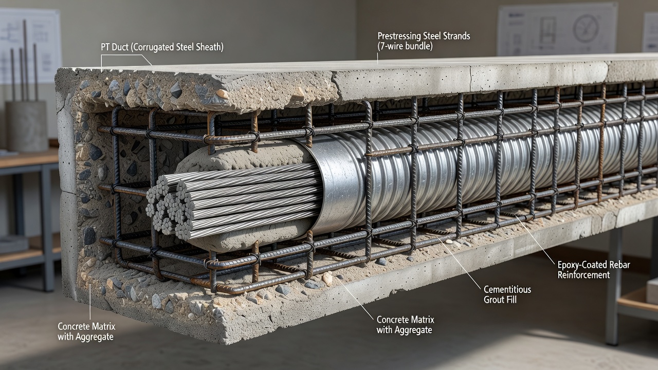
A post-tensioning duct (PT duct) is a sheath or conduit that encases post-tensioning tendons within concrete structures. It creates an engineered void that allows the high-strength steel tendon to be installed after the concrete has hardened and to move freely during the stressing operation. After the tendon is tensioned to the specified force, the duct provides a sealed pathway for the injection of cementitious grout, which fills the annular space between the tendon and the duct wall, establishing permanent bond between the steel and the surrounding concrete.
The PT duct serves five critical functions in a bonded post-tensioning system:
Void creation and tendon accommodation. The duct must maintain a clear, continuous passage through the concrete from anchorage to anchorage, following the designed tendon profile with precise vertical and horizontal alignment tolerances. The internal cross-sectional area of the duct must be sufficient to accommodate the full tendon assembly — multiple strands or bars — plus clearance for grout flow during injection. Per AASHTO LRFD Bridge Design Specifications, the minimum inside cross-sectional area of the duct must be at least 2.0 times the net area of the prestressing steel, and PTI recommends a factor of 2.0 to 2.5 to ensure adequate grout flow and complete encapsulation of all strand interstitial spaces.
Stressing pathway. The duct permits the tendon to move freely during the hydraulic jacking operation. Friction between the tendon and the duct wall is a critical design parameter that influences the magnitude of prestress losses and the required jacking force. Two friction components are considered: the curvature friction effect (μ), caused by the intentional curvature of the tendon profile, and the wobble friction effect (k), caused by unintended minor deviations in duct alignment. Per AASHTO LRFD, typical values for steel ducts are μ = 0.15–0.25 and k = 0.0002/ft, while plastic ducts generally have lower values of μ = 0.05–0.12 and k = 0.0001–0.001/ft depending on the duct profile and support spacing.
Grout containment. After stressing, the duct must be watertight to contain the cementitious grout under pumping pressure without leaks. The grout is injected at the lowest point of the tendon profile and flows upward, displacing air through vents at the high points. The duct must withstand the grout pumping pressure — typically 0.5–1.0 MPa minimum at the highest outlet — without bursting or separating at splices. Grout containment is critical: a leaking duct will result in incomplete tendon encapsulation, creating voids that become corrosion initiation sites.
Bond transfer mechanism. In bonded post-tensioning systems, the corrugations or ribs on the exterior surface of the duct provide mechanical interlock with the surrounding concrete, while the interior surface of the duct interlocks with the hardened grout. This double-interlock mechanism enables the transfer of prestressing force from the tendon through the grout and duct into the concrete section — a requirement for the development of ultimate flexural strength under overload conditions. Per ACI 318 and AASHTO LRFD, the development length for bonded prestressing strands depends on the quality of the bond between the strand and grout and between the grout and duct.
Corrosion protection barrier. The duct provides a physical barrier against moisture, chlorides, and other corrosive agents that could reach the prestressing steel. In combination with the alkaline grout (pH 12.5–13.0) and the external concrete cover, the duct forms part of a multi-layer corrosion protection system. For aggressive environments — marine exposure, deicing salt application, industrial zones — plastic ducts are specified because they provide superior corrosion resistance compared to galvanized steel ducts, which can themselves corrode and perforate over time.
Duct Types
Post-tensioning ducts are manufactured in three principal configurations, each suited to specific applications and performance requirements. The selection of duct type depends on the tendon size, tendon profile curvature, structural depth constraints, environmental exposure, and corrosion protection level required.
Corrugated Metal Ducts
Corrugated metal ducts are the traditional and most widely used duct type for bonded post-tensioning. They are manufactured by spiral-winding galvanized steel strip — typically 0.3–0.6 mm (0.012–0.024 in) thickness — into a flexible but crush-resistant tube with external helical corrugations. The corrugations provide mechanical bond between the duct and the surrounding concrete, ensuring composite action after grouting.
Material specifications. The steel strip conforms to ASTM A653/A653M with a G60 or G90 zinc coating (60 or 90 g/m² total both sides). The zinc coating provides corrosion protection during storage, handling, and construction, though it is not sufficient for long-term protection in aggressive environments. The minimum wall thickness is specified by project requirements, with thicker walls used for larger diameter ducts and more severe bending radii.
Performance characteristics. Metal ducts offer high radial stiffness that resists collapse during concrete placement, good dimensional stability, and relatively low material cost. They can be field-bent to follow curved tendon profiles, though excessive bending can cause kinking or flattening that obstructs tendon installation. The minimum bend radius for metal ducts is typically 100 times the inside diameter (R ≥ 100 Øi), meaning an 85 mm inner diameter duct has a minimum bend radius of 8.5 m.
Limitations. Metal ducts are susceptible to corrosion in high-chloride environments. The zinc coating can be consumed over time, and the galvanized steel can perforate, creating pathways for water and chlorides. There is also a potential for galvanic coupling between the zinc coating and the high-strength steel strands in the presence of an electrolyte, which can accelerate corrosion of the prestressing steel. For these reasons, many transportation agencies — including Caltrans and FDOT — now require plastic ducts for all internal tendons in bridge construction.
Corrugated Plastic Ducts
Corrugated plastic ducts are manufactured from high-density polyethylene (HDPE) or polypropylene (PP) using extrusion processes that produce a corrugated profile with external ribs. They are increasingly specified for bonded post-tensioning, particularly in aggressive environments and for structures requiring extended design life.
Performance testing per fib Bulletin 7. The Fédération International du Béton (fib) Bulletin 7, published in 2000, established the first comprehensive performance standards for corrugated plastic ducts. Seven tests are required:
Test
Purpose
Acceptance Criteria
Flexural behavior
Verifies duct is sufficiently rigid to limit deflections between supports due to temperature and concreting loads
Deflection within specified limits at 100°C
Flexibility
Confirms duct and coupler allow easy bending to minimum radius without excessive cross-section deformation
No kinking or flattening > 10% at specified radius
Lateral load resistance
Confirms duct withstands concentrated lateral loads from supports and construction
Deformation within specified limit at 500 N load
Longitudinal load resistance
Confirms duct withstands thermal restraint loads
No failure at specified tensile load
Leak tightness
Confirms watertightness of duct and couplers at minimum bend radius
No leakage under 0.1 bar air pressure
Wear resistance
Confirms duct resists abrasion from prestressing steel during stressing at minimum radius
Residual wall thickness ≥ 1.0 mm (fib) or ≥ 1.5 mm (FDOT)
Bond behavior
Confirms duct can transfer prestressing forces through corrugations
Pull-out force ≥ specified value
Advantages over metal ducts. Plastic ducts offer several critical advantages. They are inherently corrosion-resistant with no galvanic coupling potential with the prestressing steel. They provide a watertight enclosure when joints are properly heat-fused or connected with mechanical couplers. They have lower friction coefficients than steel ducts, reducing prestress losses and allowing more efficient tendon profiles. They are lighter weight — approximately one-fifth the weight of equivalent steel ducts — reducing handling labor. They can accommodate tighter bend radii through the use of specially formulated composite materials, enabling more severe tendon profiles in anchorage blisters and deviators.
Material formulations. Standard plastic duct material is HDPE, but specially formulated composite materials have been developed for tight-radius applications. These proprietary blends incorporate additives that enhance wear resistance without compromising flexibility. General Technologies Inc. (GTI) produces tight-radius duct that achieves minimum bend radii 30–50% tighter than standard plastic duct through optimized polymer blends. The cable factor k in the fib Bulletin 7 wear resistance equation accounts for the number of strands acting on the duct, with values ranging from approximately 1.8 for 5 strands to 6.3 for 37 strands.
Flat Oval Ducts
Flat oval ducts are a specialized profile used where vertical space is constrained but horizontal width is available. They have a flattened cross-section with two parallel flat sides connected by semicircular ends — essentially a rectangular shape with rounded corners. The profile maximizes horizontal strand layout while minimizing the structural depth consumed by the duct.
Applications. Flat oval ducts are used in thin concrete slabs, parking structure decks, transfer slabs in buildings, and segmental bridge decks where the available structural depth is limited by headroom or architectural constraints. In bridge decks, flat ducts allow transverse post-tensioning to be placed within the 200–275 mm typical slab thickness without excessive concrete cover requirements.
Design considerations. The reduced vertical dimension limits the number of strand layers that can be accommodated. Flat ducts also have different friction characteristics than round ducts, typically with higher wobble coefficients due to the non-circular cross-section. The transverse bending stiffness of a flat duct is less than a round duct of equivalent area, requiring closer support spacing during concrete placement. Grout flow in flat ducts may be less uniform in the transverse direction, requiring careful design of inlet and outlet locations.
Corrosion protection. Flat plastic ducts are now preferred over flat metal ducts for the same corrosion resistance reasons as round ducts. Pre-assembled flat ducts with factory-attached couplers and transition pieces are available, reducing field labor and improving quality control.
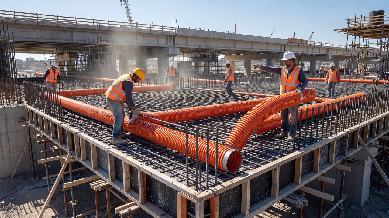
Duct Installation and Alignment
Duct installation is a precision operation that directly affects the structural performance and durability of the post-tensioning system. The FHWA Post-Tensioning Tendon Installation and Grouting Manual (FHWA-NHI-13-026, Version 2.0) provides detailed guidance on duct installation procedures.
Duct Supports
Ducts must be securely supported within the formwork to maintain the designed tendon profile during concrete placement. Support spacing is specified by project standards:
Duct Type
Maximum Support Spacing
Steel pipes (rigid)
48 inches (1.22 m)
Round plastic duct
24 inches (0.61 m)
Flat plastic duct
12 inches (0.30 m)
At splice locations
Both sides of splice
Supports are typically fabricated from deformed reinforcing bar (rebar) chairs or prefabricated steel supports that are tied to the primary reinforcement cage. The supports must be rigid enough to prevent duct displacement during concrete placement and vibration. Any deviation from the designed profile changes the tendon eccentricity and can reduce structural capacity or cause unintended stress concentrations at anchorages.
Alignment Tolerances
Duct alignment tolerances per AASHTO LRFD Bridge Construction Specifications are typically:
Vertical placement: ± 6 mm (¼ inch) from the specified profile at midspan and supports
Horizontal placement: ± 12 mm (½ inch) from the specified alignment
Angular deviation at anchorages: The duct must align with the anchorage bearing plate within 1 degree
Smooth profile: No sharp bends or kinks — the duct must conform to a smooth curve with a minimum radius not less than the manufacturer’s specified minimum bend radius
Splices and Connections
Duct splices must be watertight and provide a smooth interior alignment with no lips, steps, or kinks that could obstruct tendon installation or damage the strand surface during stressing.
Metal duct splices. Metal duct sections are joined using external couplers — cylindrical sleeves that fit over the duct ends. The coupler is crimped or self-locking onto the duct, and the joint is taped with waterproof duct tape. For critical applications, heat-shrink sleeves provide additional watertightness.
Plastic duct splices. Plastic duct sections can be joined using several methods: heat fusion welding creates a monolithic joint with full watertightness; mechanical couplers with O-ring seals provide watertight connections that can be disassembled if needed; and threaded connections are available for some proprietary systems. The coupling method must maintain the same watertightness and strength as the duct itself.
Grout Inlets and Outlets
Grout inlets are installed at the lowest points of the tendon profile, and grout outlets (vents) are installed at the highest points. Per FHWA-NHI-13-026:
Inlet pipes: Minimum 1 inch (25 mm) diameter, rigid metallic or plastic pipe, securely connected to the duct with a watertight connection
Outlet pipes: Minimum ½ inch (13 mm) diameter, extending vertically above the top of the concrete surface by at least 6 inches (150 mm)
Positive shut-off valves: Required at all inlets and outlets to maintain grout pressure during setting
Multiple inlets: For tendons longer than 100 ft (30 m) or complex profiles, additional inlets are provided at intermediate low points
Protection of Ducts During Concrete Placement
Ducts are vulnerable to damage during concrete placement. The following protective measures are specified:
Internal mandrels are inserted into metal ducts before concrete placement and rotated or withdrawn after placement to ensure the duct remains open. For plastic ducts, internal mandrels may be used for large-diameter ducts, though many plastic ducts are sufficiently stiff to maintain their shape without mandrels.
Vibration must be carefully controlled near ducts to prevent displacement or damage. Internal vibrators should not contact the duct directly.
Concrete placement sequence should balance the pour on both sides of deep webs to prevent lateral displacement of ducts.
Post-placement inspection by proving of ducts with a solid steel mandrel (undersized by 3 mm diameter relative to duct inner diameter) is required by AASHTO LRFD Construction Specifications.
Proving of Ducts
After concrete placement and before tendon installation, each duct must be proved — verified as clear and unobstructed — using a cylindrical steel mandrel. The mandrel has a diameter 3 mm less than the nominal duct inner diameter and a length equal to the minimum practical length for the application (typically 150–300 mm). The mandrel must pass through the full length of the duct from anchorage to anchorage without obstruction. If the mandrel cannot pass, the obstruction must be located and corrected before tendon installation. Proving is documented in the construction records.
Grouting Process and Quality
Grouting is the process of injecting cementitious grout into the duct after stressing to fill all voids around the tendon and create permanent bond. The grouting operation is the single most critical quality-control activity in bonded post-tensioning construction.
Grout Materials
Per PTI M55.1-19 (Specification for Grouting of Post-Tensioned Structures), the grout must meet the following requirements:
Property
Requirement
Water/cement ratio (w/c)
≤ 0.44 for pre-bagged grouts
28-day compressive strength (ASTM C109)
≥ 35 MPa (5,000 psi)
Bleed water (ASTM C940)
Zero bleed after initial mixing
Plastic expansion (ASTM C1741)
0–10% after 3 hours
Efflux time (ASTM C939 flow cone)
11–30 seconds
Maximum chloride ion content
≤ 0.08% by mass of cementitious material
Fluidity retention
≥ 30 minutes after mixing
Pre-bagged grouts are strongly preferred because they are factory-blended with precisely controlled proportions of cement, supplementary cementitious materials (silica fume, fly ash), expansion agents, plasticizers, and corrosion inhibitors. Field-mix grouts require rigorous quality control testing of each batch and are no longer permitted by most transportation agencies for bridge construction.
Thixotropic grouts are formulated to remain stiff at rest but flow readily when subjected to pumping pressure. This reversible property makes them ideal for vertical tendons and inclined web tendons where conventional grout would sag or drain. Thixotropic grouts are required by many specifications for tendons with slopes steeper than 45 degrees from horizontal.
Grouting Operations
The grouting operation must be performed within a limited time after stressing — typically ≤ 20 days, with shorter intervals specified for aggressive environments. The sequence of operations per FHWA-NHI-13-026 is:
Pre-grouting inspection. All ducts are inspected for watertightness, all vents are checked for clear passage, and the grout plant is calibrated. Air testing may be performed — pressurizing the duct to 0.1 bar and verifying pressure retention.
Grout mixing. The grout is mixed in a high-shear colloidal mixer for specified duration (typically 3–5 minutes). Water is measured precisely. The mixed grout temperature must be between 5°C and 30°C.
Fluidity testing. A sample is tested using the ASTM C939 flow cone — the efflux time must be within the specified range. Additional samples are taken for cube strength testing.
Grout injection. Grout is pumped continuously from the lowest inlet point, flowing upward through the duct. All outlets are opened sequentially until grout of the same consistency as the intake is discharged, then closed.
Pressure maintenance. Grout pressure at the highest outlet must be maintained at minimum 0.5 MPa during pumping. After all outlets are closed, the inlet pressure is maintained for 2–5 minutes to ensure complete filling.
Post-grouting inspection. All inlets and outlets are sealed. The grout caps remain pressurized during initial set (typically 4–6 hours). Grout cubes are tested at 7 and 28 days.
Vacuum Grouting
For long tendons (greater than 50 m), vertical profiles, and aggressive environments, vacuum grouting is specified. The vacuum grouting process:
A vacuum pump draws a negative pressure of approximately −0.08 MPa (−0.8 bar) at the highest outlet before grout injection.
The vacuum removes air from the duct, eliminating trapped air pockets that would remain as voids under positive-pressure-only pumping.
Grout is drawn into the duct by both the positive pumping pressure at the inlet and the negative pressure at the outlet — a pressure differential that ensures complete filling of the thin annular spaces between individual strand wires.
Vacuum grouting significantly reduces the risk of grout voids, the most common durability defect in bonded PT systems.
Grout Voids and Their Detection
Grout voids are the most common and most serious durability defect in bonded post-tensioning. A void is a volume within the duct that is not filled with grout, creating an air-filled or water-filled space where the prestressing steel is exposed to the internal duct environment rather than embedded in alkaline grout.
Causes of Grout Voids
Voids form through several mechanisms, often in combination:
Bleed water evaporation. Conventional cement-water grout naturally produces bleed water — typically 3–5% of total grout volume for standard cement/water mixes and up to 10–15% in poorly controlled mixtures. The bleed water rises to high points of the tendon profile, accumulating behind anchorages and at intermediate high points. When the bleed water evaporates over time, a void remains. This was the primary void mechanism in bridges constructed before 2001, before bleed-resistant grouts were developed.
Incomplete grouting. Poor grouting practice — insufficient pumping pressure, improper sequencing of vent closure, premature shutdown of pumping — leaves portions of the duct unfilled. Blockages in the duct from debris, crushed sections, or segregated grout can prevent grout from reaching remote portions of the tendon.
Inadequate venting. If vent tubes at high points are crushed, blocked, or omitted, air trapped at the high point cannot escape during grouting, and a void forms beneath the trapped air pocket. In congested reinforcement zones, vent tubes are vulnerable to damage during concrete placement.
Grout leakage. If the duct is not watertight — at splices, couplers, or points of duct damage — grout can leak out during injection, leaving unfilled portions. Leaked grout also compromises the corrosion protection of the tendon at the leak location.
Grout segregation. Pre-bagged grouts with excess water added in the field can segregate — the heavier cement particles settle, while the lighter water rises, creating a zone of porous, high-water-cement-ratio grout at the top of the duct. Segregation is detected through petrographic analysis of grout samples showing stratification.
Void Locations
Voids are most commonly found at:
High points of draped tendons — the highest elevation along the tendon profile, where bleed water and trapped air accumulate
Behind active anchorages — within the first 1–3 meters behind the stressing anchorage, where the tendon transitions from horizontal to the anchorage
Trumpet-to-duct transitions — the connection between the anchorage trumpet and the duct, where abrupt changes in cross-section can trap air
Intermediate high points — at pier supports in continuous bridge spans, where continuity tendons have high points at interior supports
Deviation saddles — in external tendons, at the saddles where the tendon changes direction
Consequences of Voids
Grout voids create conditions for accelerated localized corrosion of the prestressing steel. Within a void:
The protective alkaline environment (pH 12.5–13.0) provided by grout is absent
Oxygen from the air in the void replenishes continuously, sustaining the cathodic reaction
Water that condenses or accumulates in the void provides the electrolyte needed for corrosion
The high tensile stress in the prestressing steel (70–80% of ultimate) makes it susceptible to stress corrosion cracking and hydrogen embrittlement
The corrosion rate in a void can be orders of magnitude higher than in properly grouted regions. FDOT investigations have documented tendon corrosion of 10% or more of strand cross-section within voids in bridges less than 20 years old — structures designed for 75–100 year service life.
Water Ingress Through Ducts
Water ingress into post-tensioning ducts is the second most significant durability threat after grout voids. Water entering the duct system carries chlorides, sulfates, and other corrosive agents that attack the prestressing steel.
Pathways for Water Ingress
Anchorages. The anchorage is the most vulnerable entry point. Improperly sealed stressing pockets, failed encapsulation caps, ungrouted cap cavities, and gaps between the bearing plate and trumpet provide direct pathways for water to reach the wedges and strand tails. Water entering at the anchorage can migrate along the tendon for considerable distances through the interstitial spaces between individual strand wires — a phenomenon known as wick-induced water migration.
Damaged ducts. Ducts crushed or torn during construction — from over-vibration, formwork movement, or rebar congestion — create openings for water ingress. In service, corrosion of metal ducts can perforate the sheath, creating additional entry points.
Failed splices and couplers. Splices that were not properly sealed during construction or that degrade over time allow water entry at the joint.
Vents and inlets. Grout vents and inlets that are not properly sealed after grouting, or where sealants fail over time, provide water entry points at the highest points of the tendon — exactly where voids are most likely to exist.
Chloride Penetration
Chloride ions from deicing salts, marine spray, or industrial environments penetrate the concrete cover through diffusion and capillary absorption. Once chlorides reach the duct, they can enter through any opening and accumulate at the steel surface. The critical chloride threshold for prestressing steel is approximately 0.2% by mass of cement — significantly lower than the 0.4–1.0% threshold for conventional reinforcing steel — because the higher stress level makes prestressing steel more susceptible to chloride-induced pitting corrosion.
Detection of Water Ingress
Water ingress is detected through:
Visual observation of rust staining on the concrete surface along tendon profiles
Moisture testing by passing inert gas through the duct and measuring humidity levels — moisture content > 0.7% indicates high probability of corrosion (per NRC A806-1.C)
GPR detection of elevated moisture content around ducts (water has a high dielectric constant, ~80, compared to dry concrete at ~6–12)
Borescope inspection showing standing water or wet grout inside the duct
Chemical analysis of grout samples showing elevated chloride content
Duct Corrosion
Duct corrosion affects metal ducts and, in extreme cases, can compromise the duct’s protective function. Plastic ducts are inherently corrosion-resistant, eliminating this failure mode.
Corrosion Mechanism in Metal Ducts
Galvanized steel ducts corrode through several mechanisms:
Zinc consumption. The galvanized zinc coating provides sacrificial protection — the zinc corrodes preferentially to the underlying steel. In aggressive environments (high chloride, low pH, high humidity), the zinc coating can be consumed within 10–20 years.
Steel perforation. After zinc depletion, the base steel corrodes. Perforation of the duct wall creates a direct pathway for water and chlorides to reach the tendon. Pitting corrosion can produce perforation holes in 5–15 years in aggressive environments.
Galvanic coupling. In the presence of an electrolyte (water with chlorides), a galvanic cell forms between the zinc coating and the high-strength steel strands. The zinc, being more anodic, corrodes preferentially — but the galvanic potential can also drive corrosion of the strand if the zinc is consumed locally.
Detection of Duct Corrosion
Duct corrosion is detected through:
GPR signal analysis — corroded metal ducts produce different reflection characteristics than intact ducts
Half-cell potential mapping — negative potentials in the range of −350 to −500 mV CSE indicate active corrosion
Concrete cover delamination or spalling along the tendon profile — expansion of corrosion products on the duct surface causes outward pressure on the concrete
Borescope inspection through drilled ports showing rust, perforation holes, or corroded duct interior
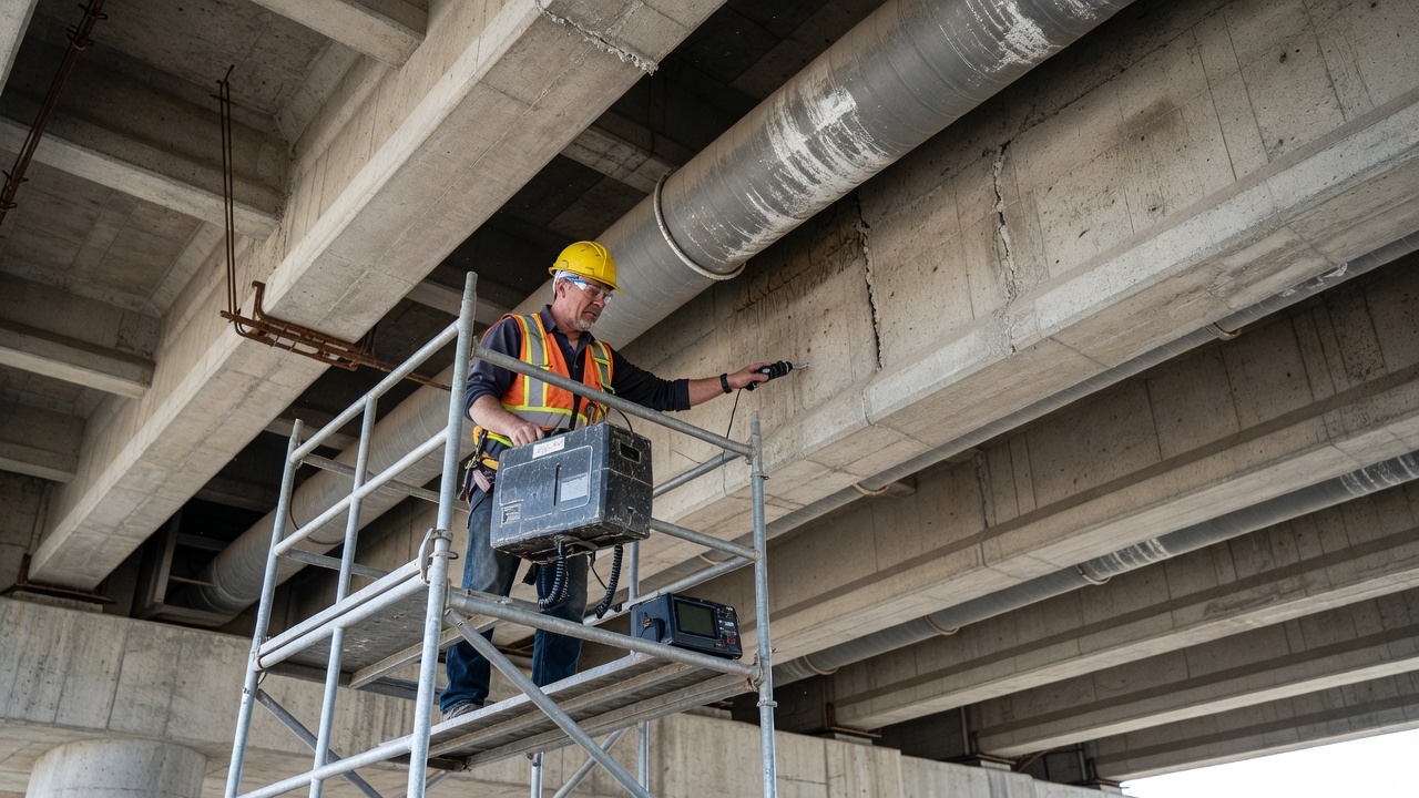
Inspection Methods
Post-tensioning duct inspection relies on a combination of non-destructive testing (NDT) methods and targeted destructive investigation. The progressive inspection protocol recommended by industry practice (per FPrimeC, FDOT, and PTI DC80.3-12) follows four steps.
Step 1: Ground-Penetrating Radar (GPR)
GPR uses high-frequency electromagnetic waves (900–1600 MHz antennas for PT inspection) transmitted into the concrete. Reflections occur at interfaces where the dielectric permittivity changes. GPR rapidly maps the complete tendon layout along the member length, identifies metallic versus plastic ducts based on signal reflection polarity, and detects moisture accumulation around ducts. A GPR survey of a typical bridge span can be completed in 2–4 hours with minimal surface preparation. The key limitation: GPR cannot reliably distinguish solid grout from soft grout or small voids because the dielectric contrast between set grout and dry air may be insufficient.
Step 2: Impact-Echo (IE) Testing
Impact-Echo is a single-sided NDT method that uses a mechanical impact to generate stress waves (2–50 kHz) in the concrete. The waves propagate into the member and reflect from internal boundaries — voids, delaminations, ducts, or the back surface. A transducer records the surface displacement caused by reflected waves, and the time-domain signal is transformed to the frequency domain using Fast Fourier Transform (FFT).
The dominant frequency f relates to the depth d of the reflecting interface by:
d = β × Vp / (2f)
where Vp is the P-wave velocity in concrete (typically 3600–4200 m/s for good quality concrete) and β is a shape factor (typically 0.96 for a plate). A grout void in a duct produces a distinct frequency shift — typically lower frequency — compared to a solidly grouted duct. IE testing is rapid, cost-effective, and requires only single-sided access.
Recent advances combine IE with deep learning — a two-stage method using impact echo and convolutional neural networks for automated grouting compactness detection, achieving >90% accuracy in identifying voids in controlled tests.
Step 3: Ultrasonic Pulse Echo (UPE) Tomography
UPE tomography uses arrays of low-frequency ultrasonic transducers (25–100 kHz) to produce 3D tomographic images of internal features. Multiple transducers are fired in sequence, and the reflected signals are processed using Synthetic Aperture Focusing Techniques (SAFT) or Full Matrix Capture with Total Focusing Method (FMC/TFM) algorithms.
UPE provides detailed cross-sectional information about duct condition — distinguishing solid grout, soft grout, voids, and water-filled voids based on acoustic impedance contrasts. Modern systems (e.g., Proceq Pundit PD8050) integrate with augmented reality visualization, providing inspectors with intuitive 3D representations of void locations.
The limitation is slower survey speed compared to GPR screening and the need for skilled interpretation. However, when UPE is used in combination with GPR for precise duct location, the detection accuracy for grout voids exceeds 85%.
Step 4: Borescope Inspection (Endoscopy)
Borescope inspection provides direct visual confirmation of internal conditions. A small-diameter fiber-optic or video borescope (typically 6–10 mm diameter) is inserted through grout inlets, outlets, or drilled inspection ports. Borescopes with articulating tips can inspect in multiple directions from a single access point, and those with camera heads provide high-resolution video and still images.
The inspector directly observes:
Grout filling level and completeness
Condition of strand surface (bright steel = passive/protected; black/dark = passivated; orange/red = active corrosion)
Presence of standing water or moisture
Void dimensions and connectivity
Grout quality (hard, soft, chalky, segregated)
Duct interior condition (corrosion of metal ducts, integrity of plastic ducts)
In the case study of the British Columbia bridge (Haixue, PTI Journal 2017), 3/4-inch holes were drilled at suspected void locations confirmed by impact-echo. Borescope inspection revealed corrosion product along strands within voids, confirming that voids of 25–33 feet in length existed and had initiated corrosion.
Validation Protocol
Per industry practice, a minimum of 5% of test locations should be validated with invasive methods — coring through the cover concrete to expose the duct, or borescope inspection through drilled ports. This validation calibrates the NDT results and provides definitive evidence of duct condition. The FDOT and FHWA both recommend progressive, multi-method protocols where GPR results inform IE/UPE test locations, and NDT results inform borescope and core locations.
Consequences of Duct Problems
The consequences of duct defects — voids, water ingress, corrosion — range from localized strand deterioration to complete structural failure.
Tendon Corrosion Mechanisms
Within a voided or water-filled duct, three corrosion mechanisms affect the prestressing steel:
Uniform corrosion. General loss of cross-section occurs over the exposed surface. The corrosion rate in a void with cyclic wetting and drying can reach 0.1–0.5 mm/year — sufficient to reduce a 5 mm diameter wire to 4 mm within 2–5 years. Since the strand is stressed to 70–80% of ultimate tensile strength, a 20% reduction in cross-section reduces the factor of safety from 1.25 to 1.0, and any additional load can cause fracture.
Pitting corrosion. Localized attack produces deep, narrow pits that act as stress concentrators. A pit only 1 mm deep in a 5 mm wire can reduce the net cross-section and create a stress concentration factor of 3–5, initiating brittle fracture at nominal stresses well below yield.
Stress corrosion cracking (SCC). The combined action of sustained tensile stress and a corrosive environment produces brittle cracks that propagate perpendicular to the stress direction. SCC in prestressing steel occurs at chloride concentrations above 0.07% by weight of grout and can cause failure within months of initiation.
Hydrogen embrittlement. Atomic hydrogen produced by corrosion reactions diffuses into the steel lattice, reducing ductility and causing sudden brittle fracture. High-strength steels (>1200 MPa tensile strength) are most susceptible — all Grade 270 prestressing strand (1860 MPa) falls in this category.
Failure Case Histories
Mid-Bay Bridge, Florida (1990s inspection). Inspection revealed a post-tensioned anchor head lying on the concrete surface with all connecting strands severely corroded. The failed tendon represented a 16% loss of structural capacity. Further investigation found split plastic duct, poor grout quality, and extensive void-related corrosion.
Sunshine Skyway Bridge, Florida. Vertical loop tendons in bridge columns exhibited corrosion exceeding 10% of their overall strand length in less than 20 years of service — a structure designed for 100-year life. Water ingress at anchorages and inadequate grout filling were the root causes.
Huntingdon Railway Viaduct, UK (Structures Moonshot project). NDT investigation using GPR, ultrasonic pulse echo, and impact-echo revealed multiple grout voids, incorrectly placed transverse reinforcement, missing horizontal reinforcement above ducts, and localized voiding around double reinforcing bars. The investigation demonstrated that multi-technology NDT approaches provide the highest confidence in identifying duct defects.
Economic Consequences
The economic impact of duct problems is substantial. Void detection and grout repair costs typically range from $5,000–$20,000 per tendon depending on access and void extent. Tendon replacement (for unbonded systems) costs $50,000–$200,000 per tendon. Full structural rehabilitation of corrosion-damaged PT bridges can exceed $10 million. The preventive cost of proper grouting and quality control during construction is a fraction of the repair cost.
Duct Repair and Regrouting
When voids are detected and confirmed, repair is essential to restore corrosion protection and structural bond.
Vacuum Grouting Repair
Vacuum grouting is the most effective repair method for existing voids. The procedure per PCI and industry practice:
Void location and access. The void location is confirmed by NDT and borescope. One or two small access holes (typically ½ to ¾ inch diameter) are drilled to intersect the void, avoiding contact with the prestressing strands.
Vacuum application. A vacuum pump is connected to one access hole, drawing a negative pressure of −0.08 MPa (−0.8 bar). The vacuum removes air and moisture from the void.
Grout injection. Low-viscosity cementitious grout or epoxy is injected through the second access hole while the vacuum is maintained. The negative pressure differential draws the grout into the void, ensuring complete filling.
Verification. Post-injection borescope inspection confirms complete void filling. If residual voids remain, the process is repeated through additional access points.
Sealing. Access holes are sealed with nonshrink grout or epoxy. The repair is documented in the maintenance records.
Key Advantages of Vacuum Grouting
Only one access hole is required for vacuum application
The grout fills the void completely without needing additional vents
The negative pressure removes moisture from the void before grouting
The process works for both small localized voids and large extended voids
Limitations
The void must be accessible — confined or geometrically complex void spaces may require multiple access points
The duct must be sufficiently intact to maintain vacuum — large duct breaches will prevent vacuum retention
Void repair does not address existing corrosion damage — significantly corroded strands may require additional corrosion mitigation or structural strengthening
Regrouting of Large Voids
For long voids (exceeding 5–10 meters), the vacuum grouting process is performed sequentially — the void is divided into segments by drilling access holes at intervals, and each segment is vacuum-grouted independently. This ensures complete filling of the entire void length without risk of trapping air pockets.
Corrosion Mitigation After Repair
After regrouting, corrosion mitigation options include:
Cathodic protection — impressed current or galvanic anode systems for severely corrosive environments
Impregnation — application of corrosion-inhibiting compounds that penetrate the grout and reach the strand surface
Environmental control — sealing the structure to prevent further water ingress, improving drainage at anchorages, and applying surface coatings to the concrete
Summary
The post-tensioning duct is a critical component of bonded PT systems, serving the essential functions of void creation, tendon accommodation, grout containment, bond transfer, and corrosion protection. Duct types include corrugated metal (traditional, economical, but corrosion-susceptible), corrugated plastic (corrosion-resistant, watertight, lower friction), and flat oval (space-constrained applications). Proper duct installation — including support spacing, alignment tolerance, watertight splices, and grout inlet/outlet placement — is essential for system performance. Grouting quality is the single most important factor governing long-term durability, with modern pre-bagged, bleed-resistant grouts and vacuum grouting techniques significantly reducing the risk of voids. Detection of grout voids, water ingress, and duct corrosion requires a progressive multi-method NDT approach combining GPR, impact-echo, ultrasonic pulse echo, and borescope inspection. Duct problems — voids, water ingress, corrosion — lead directly to tendon corrosion and potential structural failure if not detected and repaired. Vacuum grouting is the most effective repair method for existing voids.
Compiled from FHWA-NHI-13-026 Post-Tensioning Tendon Installation and Grouting Manual (2013), PTI M55.1-19 Specification for Grouting of Post-Tensioned Structures, PTI TAB.3-13 Post-Tensioning Terminology, AASHTO LRFD Bridge Design and Construction Specifications, fib Bulletin 7 (2000), Fédération International du Béton, PTI Journal Technical Papers (Haixue 2017), FDOT corrosion investigation reports, PCI vacuum grouting guidelines, Screening Eagle/Proceq case studies, FPrimeC NDT methodology, Caltrans plastic duct research, and industry technical resources.
Frequently Asked Questions
The post-tensioning duct serves multiple critical functions. First, it creates a void in the concrete that allows the tendon to be installed after the concrete has hardened and to move freely during the stressing operation. Second, after stressing, the duct provides a sealed pathway for the injection of cementitious grout, which fills the annular space around the strands. Third, the duct — particularly corrugated types — provides mechanical interlock between the grout and the surrounding concrete, enabling the transfer of bond stresses in bonded post-tensioning systems. Fourth, the duct acts as a physical barrier against moisture and chlorides, contributing to the corrosion protection system. Fifth, the duct maintains the tendon profile during concrete placement, preventing displacement of the tendon from its designed eccentricity. Without the duct, the tendon could not be stressed after concrete hardening, and the bond transfer mechanism in bonded PT systems would be impossible.
Post-tensioning ducts are manufactured in three principal types. Corrugated metal ducts are spiral-wound from galvanized steel strip, typically 0.3–0.6 mm wall thickness, with external helical corrugations that provide mechanical bond with concrete. They are the traditional choice and offer high strength at low cost. Corrugated plastic ducts (HDPE or PP) are increasingly preferred for aggressive environments because they are inherently corrosion-resistant, have no galvanic coupling with steel, provide a watertight enclosure when properly connected, and have lower friction coefficients than steel ducts. Flat oval ducts are a specialized profile used where vertical space is limited — typically in thin slabs and building applications — with a flattened cross-section that maximizes horizontal width while minimizing structural depth. Each type must meet specific performance requirements per PTI M55.1, fib Bulletin 7, and AASHTO LRFD, including minimum bend radius, wear resistance, lateral load resistance, leak tightness, and bond behavior testing.
Grout voids in PT ducts are detected using several non-destructive testing (NDT) methods, typically applied in a progressive protocol. Ground-Penetrating Radar (GPR) using 900–1600 MHz antennas locates tendon ducts and maps their profile, but cannot reliably distinguish solid grout from voids. Impact-Echo (IE) testing generates stress waves from a mechanical impact and analyzes reflected frequency shifts — voids produce distinct low-frequency resonance compared to solid grout, typically shifting the dominant frequency downward by 20–50%. Ultrasonic Pulse Echo (UPE) tomography uses arrays of 25–100 kHz transducers to produce 3D tomographic images based on acoustic impedance contrasts, detecting voids, soft grout, and corrosion. The most definitive method is borescope inspection — a small-diameter fiber-optic or video probe inserted through grout inlets, outlets, or drilled 3/4-inch inspection ports provides direct visual confirmation of void size, location, strand condition, and moisture presence. Per industry practice (FPrimeC, FDOT), a minimum of 5% of test locations should be validated with invasive confirmation.
Duct problems — including incomplete grout filling, water ingress, duct corrosion, and duct damage — lead directly to tendon corrosion, the most significant durability threat in post-tensioned structures. Grout voids at high points of draped tendons accumulate water and oxygen, creating localized electrochemical corrosion cells. Corrosion reduces the tendon cross-sectional area, and because prestressing steel operates at 70–80% of ultimate tensile strength, even modest section loss (10–15%) can cause sudden brittle fracture without prior visible warning. Water ingress through leaking ducts introduces chlorides (from deicing salts or marine environments) that break down the passive oxide layer on the steel. Duct corrosion in metal ducts can perforate the sheath, creating pathways for further water and chloride ingress. The consequences range from localized strand corrosion requiring repair to complete tendon failure. In extreme cases, multiple tendon failures can compromise structural capacity, as documented in FDOT investigations of the Mid-Bay Bridge and Sunshine Skyway Bridge where corrosion-related tendon failures required major structural repairs.
Post-tensioning ducts are governed by multiple standards. PTI M55.1-19 (Specification for Grouting of Post-Tensioned Structures) covers grout materials and compatibility with ducts. PTI/ASBI M50.3-12 covers system components including duct materials and acceptance testing. AASHTO LRFD Bridge Design Specifications (Article 5.9) requires minimum duct inside area ≥ 2.0 times the tendon net area and specifies friction coefficients for design. AASHTO LRFD Bridge Construction Specifications (Section 26) covers duct materials, installation tolerances, splices, supports, and proving of ducts. fib Bulletin 7 (2000) provides testing standards for corrugated plastic ducts including flexural behavior, flexibility, lateral load resistance, longitudinal load resistance, leak tightness, wear resistance, and bond behavior. ASTM A416 covers prestressing strand, while duct-specific material standards reference galvanized steel per ASTM A653 or HDPE per ASTM D3350. FDOT Standard Specifications impose more stringent acceptance criteria for wear resistance testing (1.5 mm residual wall thickness for ducts up to 85 mm, 2.0 mm for larger ducts) compared to fib Bulletin 7 minimum (1.0 mm).
Need PT Duct Inspection and Grout Void Detection?
TarmacView provides expert non-destructive evaluation services for post-tensioned bridges and concrete infrastructure, including impact-echo, GPR, and ultrasonic testing for PT duct condition assessment. Contact us to schedule a grout void survey or tendon inspection.
Grouting is the injection of cementitious grout into post-tensioning tendon ducts after stressing, providing bond between tendon and concrete, and protecting th...
Post-tensioning (PT) is a method of prestressing concrete where high-strength steel tendons are tensioned after concrete hardening, applying compressive stress ...
A prestressing tendon is a high-strength steel element — typically seven-wire strand, wire, or bar — used in prestressed or post-tensioned concrete to apply per...
25 min read
Reinforcement
Bridges
+4
Cookie Consent We use cookies to enhance your browsing experience and analyze our traffic. See our privacy policy.