What is Power Factor?
Power Factor (Electrical Engineering)
Power factor is a foundational concept in alternating current (AC) electrical systems, reflecting how effectively supplied power is converted into useful work. It is crucial for engineers, facility managers, and utility providers because it directly impacts system efficiency, infrastructure sizing, operational costs, and grid stability.
What is Power Factor?
Power factor is a dimensionless number, ranging from 0 to 1, that quantifies how efficiently electrical power supplied to a circuit is turned into productive work. It is defined as:
[ \text{Power Factor (PF)} = \frac{\text{Real Power (kW)}}{\text{Apparent Power (kVA)}} ]
- Real Power (P, kW): The portion of power that performs actual work (e.g., turning a motor).
- Apparent Power (S, kVA): The product of the total current and voltage supplied, representing the combination of both useful and wasted energy.
- Reactive Power (Q, kVAR): Power that oscillates between source and load, necessary for magnetic fields but not converted into work.
A power factor of 1 (unity) means all supplied power is used for productive work. Lower values indicate inefficiency, with more energy lost as heat or used to sustain magnetic or electric fields.
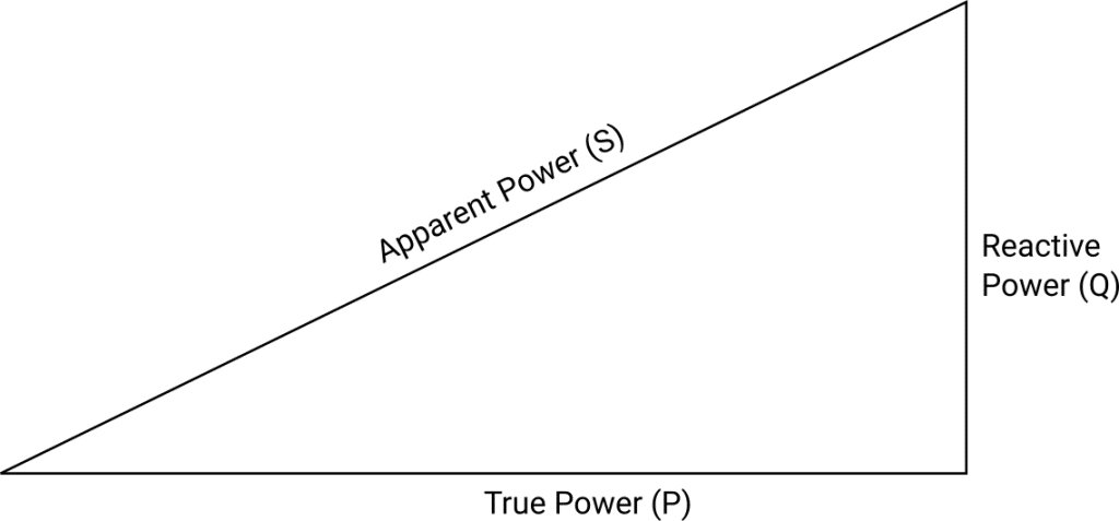
The Power Triangle
The power triangle visually represents the relationship between real, apparent, and reactive power:
- Horizontal (P): Real power (kW) – does useful work.
- Vertical (Q): Reactive power (kVAR) – does not perform work, but is necessary for inductive/capacitive processes.
- Hypotenuse (S): Apparent power (kVA) – total required from source.
[ S^2 = P^2 + Q^2 ]
The angle between P and S (θ) relates to the power factor:
[
\text{Power Factor} = \cos(\theta)
]
A larger phase angle (greater deviation from in-phase conditions) means a lower power factor and more inefficiency.
Analogy: The Horse and Railcar
Imagine a horse pulling a railcar with the harness at an angle:
- Total effort = Apparent Power (S)
- Forward movement = Real Power (P)
- Sideways effort = Reactive Power (Q)
If the horse pulls directly forward (power factor = 1), all effort is useful. At an angle, much is wasted “sideways” (lower power factor).
Types and Calculation
- Linear Loads (sinusoidal): Power factor equals the cosine of the phase angle between voltage and current.
- Nonlinear Loads (distorted): Power factor is reduced by both phase displacement and harmonics. True power factor includes effects of Total Harmonic Distortion (THD).
[ \text{Power Factor} = \frac{P}{V_{\text{rms}} \cdot I_{\text{rms}}} ]
- Lagging Power Factor: Current lags voltage (inductive loads).
- Leading Power Factor: Current leads voltage (capacitive loads).
- Unity Power Factor: Voltage and current are in phase (purely resistive loads).
How Is Power Factor Used?
System Efficiency and Design
High power factor means efficient power usage. Low power factor requires higher current for the same real power, increasing heat losses (( I^2R )), voltage drops, and equipment wear. It also means cables, transformers, and generators must be sized for higher apparent power, increasing capital and operational costs.
Utility Billing and Penalties
Utilities often charge for both real and apparent power. Low power factor results in higher demand charges or penalties, as the grid must be sized for maximum apparent power. Maintaining a high power factor minimizes these costs.
Instrumentation and Measurement
Modern power analyzers, energy management systems, and plug-in meters allow continuous monitoring of power factor, helping to identify and correct inefficiencies.
Examples and Use Cases
Industrial Facilities
Factories with many motors, welders, and transformers often have low (lagging) power factor. Correction capacitors are often installed to offset inductive effects and minimize utility penalties.
Commercial Buildings
Offices, malls, and hospitals use motors (elevators, HVAC) and lighting with ballasts, lowering power factor. Centralized or distributed correction is common.
Power Supplies and Electronics
Nonlinear loads such as computers and LED drivers distort current waveforms, lowering power factor. Active power factor correction (PFC) in modern electronics helps meet regulatory standards and improve efficiency.
Residential Use
While most residential loads are resistive, appliances with motors and certain lighting technologies can lower power factor. Residential users are rarely penalized, but collectively these loads can impact grid efficiency.
Causes of Low Power Factor
- Inductive Loads: Motors, transformers, and ballasts require current for magnetic fields, causing current to lag voltage.
- Capacitive Loads: Over-correction or long cables under light load can cause leading power factor.
- Nonlinear Loads: Devices like SMPS and VFDs introduce harmonics, distorting current waveforms and reducing true power factor.
Consequences of Low Power Factor
- Increased System Losses: Higher current means more heat and wasted energy in cables and transformers, reducing equipment life.
- Reduced System Capacity: Infrastructure must be oversized for higher apparent power, increasing costs.
- Utility Penalties: Many utilities impose extra charges for low power factor, increasing operational expenses.
- Voltage Regulation Problems: More current leads to greater voltage drops, potentially causing equipment malfunction or failure.
Power Factor Correction
Methods
- Capacitor Banks: Provide leading reactive power to offset inductive loads, commonly used in industrial and commercial settings.
- Synchronous Condensers: Rotating machines supplying reactive power, used in large grids.
- Active Power Factor Correction: Electronic circuits in modern devices shape current to improve power factor and reduce harmonics.
Benefits
- Lower energy bills
- Reduced losses and heat
- Avoided utility penalties
- Increased equipment and system lifespan
Real-World Example
A manufacturing plant operating motors with a power factor of 0.7 will draw 43% more current for the same real power compared to unity power factor. Installing capacitor banks can raise the power factor above 0.95, reducing current, losses, and penalties.
Monitoring and Standards
Energy management systems and modern meters allow real-time power factor tracking. International standards (such as IEC 61000-3-2) set minimum power factor requirements for electronic equipment to ensure grid efficiency and quality.
Power factor is not just a technical metric, it’s a key driver of energy efficiency, cost savings, and system reliability in every AC electrical network.
If you want to optimize your facility’s power factor, boost efficiency, and lower costs, our experts can help design and implement a solution tailored to your needs.
Frequently Asked Questions
- What is power factor?
- Power factor is the ratio of real power (kW) to apparent power (kVA) in an AC circuit. It indicates how effectively electrical power is being used for productive work. A power factor of 1 means all supplied power is used efficiently, while lower values indicate inefficiency and that some energy is wasted as reactive power.
- Why is a low power factor a problem?
- Low power factor means more current is required to deliver the same real power, which increases system losses, requires larger infrastructure, and often results in penalties from utility companies. It also reduces overall system capacity and can cause voltage drops, affecting equipment performance.
- How can power factor be improved?
- Power factor is commonly improved by installing power factor correction equipment such as capacitor banks, synchronous condensers, or active correction devices. These counteract the effects of inductive or nonlinear loads, reducing reactive power and harmonics to bring power factor closer to unity.
- What causes low power factor?
- The main causes are inductive loads (motors, transformers), capacitive over-correction, and nonlinear loads (such as devices with switch-mode power supplies or variable frequency drives) that introduce harmonic distortion, all of which reduce the system's true power factor.
- How is power factor measured?
- Power factor is measured using power analyzers or energy management systems that monitor real, reactive, and apparent power. For complex or nonlinear loads, advanced meters account for both phase shift and harmonic distortion to provide an accurate measurement.
This is a reference entry. TarmacView provides drone inspection services and doesn't sell the equipment or materials described in this glossary.