Prestressed Concrete Pavement
Prestressed concrete pavement (PCP) is a rigid pavement system in which internal compressive stresses are introduced into the concrete slab before service loads...
Pavement
Concrete
+3
Precast concrete pavement uses factory-fabricated concrete slabs installed on-site, enabling rapid construction and repair with minimal lane closure time. Precast panels are post-tensioned or connected via dowel bars. Covers precast pavement types, joint details, bedding/grouting, and inspection for panel settlement, joint performance, and bedding erosion.
Precast Concrete Pavement (PCP) is a modular pavement technology in which Portland cement concrete (PCC) slabs are fabricated in a controlled plant environment, transported to the project site, and installed on a prepared base or subbase. Unlike conventional cast-in-place concrete pavement — where concrete is mixed, placed, finished, and cured in the field — PCP panels arrive at the site fully cured and ready for immediate installation, eliminating the critical path constraint of field curing time.
The Federal Highway Administration (FHWA) defines PCP technology as encompassing two primary system categories: Jointed Precast Concrete Pavement (JPrCP), which uses reinforced or pretensioned panels installed singly or in a continuous series with load transfer at each transverse joint; and Post-Tensioned Precast Concrete Pavement (PPCP), which incorporates thinner panels installed in a continuous series and post-tensioned together using high-strength steel tendons, resulting in significantly fewer transverse joints. A third category — incrementally connected precast pavement — uses mechanical connectors or tie bars to link panels sequentially during installation.
PCP technology is used for two distinct application types: intermittent repairs — isolated full-depth joint repairs or full panel replacement in existing pavements — and continuous applications — full-scale project-level rehabilitation or reconstruction of longer pavement sections. The FHWA reports that service life expectations are at least 20 years for intermittent repairs and at least 40 years for continuous applications without significant future corrective treatment, based on field performance data from projects constructed across the United States since the early 2000s.
The primary drivers for selecting PCP over cast-in-place concrete are construction speed and traffic impact minimization. PCP enables completion of pavement repairs during single overnight lane closures of 8 hours or less, restoring traffic by morning. According to the SHRP2 Project R05 report, PCP is most cost-effective on routes carrying over 100,000 vehicles per day where lane closure costs exceed $100,000 per day and where alternative routes for detouring traffic are unavailable. On such routes, the premium cost of precast panels (typically 15–30 percent higher than equivalent cast-in-place concrete) is offset by the elimination of traffic delay costs and the avoidance of extended work zone durations.
The FHWA, based on a comprehensive review of projects constructed in the United States and field testing of selected installations, has identified five key attributes that successful PCP systems must achieve:
Constructability — Techniques and equipment are available to ensure acceptable production rates for panel installation. The construction process must accommodate the logistic demands of just-in-time panel delivery, crane positioning, bedding placement, grouting operations, and joint completion within a single lane closure window. Typical production rates for continuous PCP installation range from 20 to 40 panels per night depending on crew experience, panel size, and site constraints.
Concrete Durability — Plant fabrication of precast panels produces concrete of superior strength and durability compared to field-placed concrete. Factory conditions enable precise control of water-cement ratio (typically 0.38–0.42), accurate aggregate batching, controlled curing temperature (accelerated steam curing or moist curing at 70–100°F), and consistent consolidation through table vibration. The result is concrete with 28-day compressive strengths of 5,000–8,000 psi (34.5–55 MPa), low permeability (chloride ion penetration less than 1,000 coulombs per ASTM C1202), and high freeze-thaw durability (durability factor exceeding 90 percent per ASTM C666).
Load Transfer at Joints — Reliable and economical techniques provide effective load transfer at transverse joints in both jointed and prestressed PCP systems. Load transfer efficiency (LTE) — the ratio of deflection on the unloaded side of a joint to deflection on the loaded side — must exceed 70 percent (and preferably 80 percent) for satisfactory long-term performance. PCP achieves this through dowel bars installed in preformed slots, with alignment tolerances that ensure unrestricted joint movement while maintaining continuous load transfer.
Panel Support — Adequate and uniform base support conditions are essential. The bedding layer (interlayer) compensates for the mismatch between the flat panel bottom and the graded base surface, filling voids and ensuring full contact. The FHWA Tech Brief HIF-16-009 emphasizes that the best-constructed precast panels cannot perform well if placed on poor support. Non-uniform support leads to the “bridge syndrome” where panels are held in place only by joint load transfer mechanisms, resulting in rapid deterioration.
Performance and Efficiency — PCP panels can be thinner than equivalent cast-in-place concrete slabs because of prestressing and/or reinforcing elements. Post-tensioned PCP panels are typically 6–8 inches thick for highway applications compared to 10–12 inches for cast-in-place JPCP, reducing material quantities and enabling installation over existing base layers with minimal excavation.
Jointed Precast Concrete Pavement is the most widely used PCP system in the United States. JPrCP uses individual precast panels that are reinforced or pretensioned, installed singly or in a continuous series, with load transfer provided at every transverse joint. The FHWA Guide Specification FHWA-HIF-19-017 defines the materials, fabrication tolerances, installation procedures, and acceptance criteria for JPrCP.
JPrCP panels are fabricated with preformed dowel bar slots at the transverse joint faces. The slot configuration varies by proprietary or agency-specific design:
| Slot Type | Description | Agency/Proprietor |
|---|---|---|
| Bottom slot | Dowel bar slots at bottom of panel, grouted after placement | Multiple proprietary systems |
| Top slot (narrow) | Narrow slots at panel surface, partially open after grouting | Illinois Tollway (non-proprietary) |
| Teardrop top slot | Teardrop-shaped surface slots widening toward dowel | Caltrans (non-proprietary) |
| Hybrid top slot and duct | Combination of surface slot and internal duct | Proprietary systems |
The slot depth must not exceed half the panel thickness plus 1.25 inches. For top slots, the width at the top surface is a maximum of 1.5 inches and the width at the dowel location is 2.5 to 3.5 inches. For bottom slots, the width at the bottom surface is a maximum of 2.5 inches and at the dowel location 3.0 to 3.5 inches. Slot length does not exceed the dowel bar length plus 1 inch.
JPrCP is the preferred system for intermittent repairs and for continuous applications up to about 1 mile in length. Individual panels are typically 12 feet long by 12 feet wide (matching standard lane width) with thickness of 8 to 12 inches depending on traffic loading. The system requires a transverse joint at every panel end, which means approximately 440 joints per mile of pavement — each joint requiring dowel bars, slot grouting, and joint sealant installation.
Post-Tensioned Precast Concrete Pavement uses thinner panels (typically 6–8 inches for highway applications) that are installed in a continuous series and post-tensioned together using high-strength steel strands or bars. The post-tensioning tendons are threaded through preformed ducts cast into each panel, and after all panels in a series are placed, the tendons are stressed to apply a compressive force of 200–400 psi (1.4–2.8 MPa) to the entire pavement system.
PPCP offers significant advantages over JPrCP: fewer transverse joints (post-tensioning runs of 200–500 feet are typical, reducing joint count by 90 percent compared to JPrCP); thinner panels requiring less material; continuous prestress that minimizes crack formation and keeps cracks tightly closed when they occur; and improved load transfer at joints because the continuous compression provides inherent shear transfer across cracks.
The California Department of Transportation (Caltrans) has developed standard plans and specifications for both jointed and post-tensioned PCP and has constructed multiple projects using PPCP, including installations with several hundred to several thousand panels. Caltrans requires grout-supported panels for all PCP installations to ensure uniform support.
PPCP limitations include: greater design complexity; the need for specialized post-tensioning equipment and trained crews; longer initial installation time per panel due to tendon threading and stressing operations; and the difficulty of replacing individual panels in a post-tensioned series if a panel is damaged during service.
Incrementally connected precast pavement is a hybrid system where panels are connected sequentially during installation using mechanical connectors, tie bars, or welded plate connections rather than post-tensioning. This system provides continuous structural action but allows panels to be installed incrementally without requiring the full tendon installation and stressing operations of PPCP.
Incrementally connected systems are less common than JPrCP or PPCP and are primarily used for specialized applications such as bridge approach slabs, where the connection to the bridge structure and the need for a smooth transition zone make incremental connection advantageous. The connections are designed to transfer shear and tension between adjacent panels while accommodating thermal expansion and contraction.
Precast concrete panels are manufactured in dedicated precast plants using pre-engineered forms that replicate the exact panel geometry, dowel bar slot configuration, and surface texture specified in the contract documents. The fabrication process follows a controlled sequence:
Form preparation and reinforcement placement — Steel forms are cleaned, oiled, and assembled to the required panel dimensions. Welded wire fabric (WWF) or deformed reinforcing bars are placed within the form with specified concrete cover of 2 inches minimum for the top surface (traffic surface) and 1.5 inches for the bottom. Prestressing strands (for pretensioned panels) are tensioned to the required force before concrete placement.
Dowel bar and slot former installation — Slot formers or void formers are positioned at the transverse joint faces to create the precise geometry for dowel bar slots. Dowel bars are supported at mid-depth of the panel within the slot formers and held to tight alignment tolerances: vertical alignment within ± 0.25 inches of mid-depth and horizontal alignment within ± 0.125 inches of the planned position.
Concrete placement and consolidation — Concrete with specified slump of 1–3 inches (25–75 mm) and air content of 6.5 percent ± 1.5 percent is placed in the form and consolidated using table vibration and/or internal vibrators. Surface finishing produces the specified texture — typically burlap drag for highway pavements or tining/grooving for airfield pavements.
Curing — Panels are cured using either accelerated steam curing (temperature raised to 120–150°F over 3–6 hours and held for 6–12 hours) or moist curing at 70–100°F for 7 days. Accelerated curing enables panels to be stripped from forms within 24 hours of casting and transported to storage yards within 3–5 days.
The FHWA Guide Specification FHWA-HIF-19-017 specifies the following fabrication tolerances for precast concrete panels:
| Parameter | Tolerance | Test Method |
|---|---|---|
| Panel length | ± 0.125 inches (3 mm) | Steel tape, measured at mid-depth |
| Panel width | ± 0.125 inches (3 mm) | Steel tape, measured at mid-depth |
| Panel thickness: ≤ 10 inches | ± 0.125 inches (3 mm) | Caliper or depth gauge |
| Panel thickness: > 10 inches | ± 0.25 inches (6 mm) | Caliper or depth gauge |
| Squareness | 0.0625 in/ft of dimension (5 mm/m) | Diagonal measurement difference |
| Surface flatness | 0.125 inches under 10-ft straightedge | Straightedge and feeler gauge |
| Dowel bar vertical alignment | ± 0.25 inches of mid-depth | Depth measurement from surface |
| Dowel bar horizontal alignment | ± 0.5 inches end to end | String line or laser |
| Slot width (top/bottom) | ± 0.125 inches | Caliper |
| Slot depth | ± 0.25 inches | Depth gauge |
Panels that fail to meet these tolerances are rejected and must be replaced at the contractor’s expense. Defective panels that arrive at the project site are flagged and removed before installation begins.
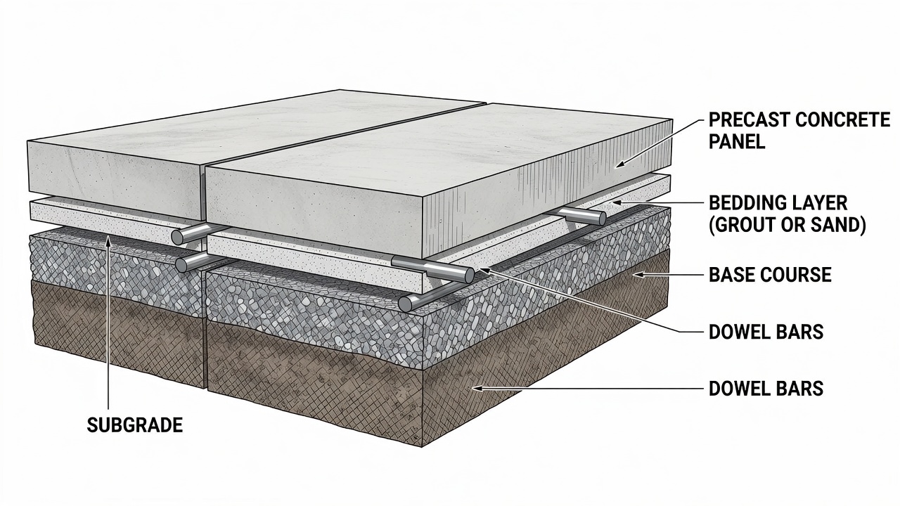
The bedding layer (interlayer) between the precast panel bottom and the prepared base surface is arguably the most critical element affecting long-term PCP performance. The FHWA Tech Brief HIF-16-009 states categorically: “The support under the panels needs to be firm (strong) and uniform. The best-constructed precast panels cannot perform well if they are placed on poor support.”
The bedding layer serves two primary functions: grade control — compensating for surface irregularities in the existing or new base to achieve the required pavement elevation and cross-slope; and void filling — ensuring full contact between the panel bottom and the support surface to prevent bending stresses that would crack the panel under traffic loading.
Three bedding support systems are recognized by FHWA, each with distinct material properties, installation procedures, and performance characteristics.
Rapid-setting cementitious grout is the most commonly specified bedding material for JPrCP and PPCP systems in the United States. The grout is a flowable, self-leveling, non-shrink cementitious material that achieves compressive strength of 3,000–5,000 psi (20.7–34.5 MPa) at 24 hours.
The installation sequence for grout-supported panels is: panels are set approximately 0.25–0.5 inches (6–13 mm) above the completed base using a leveling lift system — typically four or more threaded setting bolts embedded in the panel and adjusted from the surface using a wrench or Allen key. After the panels are aligned and the dowel bars in the slots are engaged, the gap under the panel is pumped full of bedding grout through pre-drilled grout ports (typically 1.5–2 inch diameter holes at each corner and mid-panel). The grout is pumped until it exits all vent holes, confirming complete filling.
The setting bolts are backed off after the grout has reached initial set (typically 1–2 hours), transferring the panel weight to the grout layer. Final bolt holes are patched with non-shrink grout. The completed bedding provides uniform support across the entire panel area, preventing point loading and the “bridge syndrome” where unsupported panels are held only by joint load transfer.
Cementitious bedding requires careful quality control: the grout must be kept fluid enough to flow under the panel but must not be so fluid that it migrates beyond the panel area or loses strength. Water-cement ratio is tightly controlled at 0.35–0.40 maximum, and a high-range water reducer is typically used to achieve flowability without excess water. Temperature restrictions apply: bedding grout is not placed when ambient temperature is below 40°F (4°C) or above 95°F (35°C) without special provisions.
High-density polyurethane foam bedding is an alternative bedding system used primarily for repair applications where immediate support is required and rapid reopening to traffic is critical. The polyurethane system uses two liquid components — a polymeric isocyanate and a polyol resin — that are injected through predrilled holes in the precast panel (typically 0.5–0.75 inch diameter holes at 3–4 foot spacing).
The chemical reaction between the two components produces an exothermic foaming action that lifts the panel to the correct grade and fills all voids between the panel bottom and the base. The foam expands to 10–20 times its liquid volume within seconds of injection, generating lift pressure of 5–15 psi depending on the formulation. Full cure (95 percent of ultimate strength) occurs within 15–30 minutes at 70°F, after which the panel can be opened to traffic.
Polyurethane foam offers distinct advantages: no curing time (traffic can be opened within 30–60 minutes of injection); excellent void-filling capability (the foam flows into irregular voids and gaps); minimal equipment requirements (a single injection rig and two-component metering pump); and the ability to lift settled panels back to grade through precision injection (controlled lifts of 0.01–0.1 inches per injection cycle).
Limitations include: higher material cost than cementitious grout ($3–$5 per square foot compared to $0.50–$1.00 per square foot for grout); sensitivity to moisture at the injection interface (the foam will not bond to wet surfaces); and the difficulty of verifying complete void filling beneath large panels. Polyurethane is not recommended for continuous PCP applications where the bedding must provide long-term uniform support under heavy traffic.
Granular sand bedding is the simplest and lowest-cost bedding system, used primarily for low-traffic applications and for installations where the base surface is well-graded and uniform. A thin layer of fine, clean sand — typically 0.125–0.25 inches (3–6 mm) thick — is spread on the prepared base surface immediately before panel placement. The panel is then positioned and seated into the sand layer using static weight (the panel’s own weight) or light vibration.
The FHWA Tech Brief HIF-16-009 notes that granular bedding thickness should be limited to a maximum of 0.25 inches for repair applications because thicker uncompacted granular material consolidates under traffic, causing panel settlement. There is no benefit in providing thicker granular bedding, and the use of thicker non-compactable granular material may be detrimental to long-term pavement performance.
When granular bedding is used, panels must be undersealed — a flowable cementitious grout is injected after panel installation to fill any remaining voids or gaps under the panel. The undersealing grout compensates for the limited uniform support provided by the sand layer alone.
Granular bedding is discouraged for continuous PCP applications and for airfield pavements because the inherent non-uniformity of support leads to differential panel settlement and joint faulting over time. The NPCA Manual for JPrCP recommends that granular bedding be used only for temporary repairs or for permanent repairs on low-volume roads with less than 500 vehicles per day.
Effective load transfer at transverse joints is essential for the long-term performance of jointed precast concrete pavement. Load transfer refers to the ability of a joint to distribute a wheel load applied on one side of the joint to the adjacent panel on the other side, thereby reducing the deflection and stress at the joint edge. The standard metric is Load Transfer Efficiency (LTE) , defined as the ratio of the deflection on the unloaded side to the deflection on the loaded side, expressed as a percentage. The FHWA recommends a minimum LTE of 70 percent at installation and 80 percent for long-term satisfactory performance.
PCP achieves load transfer through dowel bars — smooth, round steel bars that bridge the joint, transferring shear forces from the loaded panel to the unloaded panel while allowing unrestrained horizontal movement (opening and closing of the joint due to thermal expansion and contraction).
Per the FHWA Guide Specification, dowel bars for JPrCP systems meet the following requirements: diameter of 1.25 to 1.5 inches (32–38 mm) for standard highway applications and 1.5 inches (38 mm) for airfield pavements; length of 18 inches (457 mm) ; spacing of 12 inches (305 mm) across the joint width; and location at mid-depth of the slab (± 0.25 inches vertical tolerance). Bars are epoxy-coated (per AASHTO M-284) for corrosion protection, and one end of each bar is fitted with an expansion cap (typically a plastic or PVC sleeve 2–3 inches long) to allow free horizontal movement as the joint opens and closes.
The dowel bars are pre-positioned in the panel slots during fabrication. The slots are formed using removable void formers or permanent slot liners. After the adjacent panel is placed and the dowel bars are engaged in the matching slots, the slots are filled with non-shrink cementitious grout (compressive strength minimum 5,000 psi at 24 hours) or epoxy patching material depending on the slot type and agency specification.
The slot grouting operation is critical to load transfer performance. For top slots, the slots are cleaned with compressed air, moistened, and filled with grout that is struck off flush with the pavement surface. The grout must be consolidated to eliminate voids around the dowel bars, typically using a small-diameter rod or vibration applied to the slot sides.
For bottom slots, grouting is performed before the panel is fully seated, while the slots are still accessible from the side. After grouting, the panel is lowered onto the bedding layer, and the grout is allowed to cure before traffic loading.
After slot grouting, the transverse joint itself is sealed with a hot-poured or cold-applied joint sealant per AASHTO or agency specifications. The joint sealant reservoir is formed by sawing a 0.25-inch wide by 1.5-inch deep slot centered over the joint after the grout has cured. The sealant prevents water infiltration and incompressible material intrusion into the joint.
Precast concrete pavement for airport runways, taxiways, and aprons is governed by FAA Advisory Circular AC 150/5370-16 — Rapid Construction of Rigid (Portland Cement Concrete) Airfield Pavements. Airfield PCP must satisfy requirements that go beyond highway applications: higher load magnitudes from aircraft (Boeing 747 gear loads exceed 100,000 pounds per strut); wider panels to match existing pavement geometry; stricter surface smoothness tolerances (maximum 0.125-inch deviation under 16-foot straightedge per FAA standards); and Foreign Object Debris (FOD) prevention — all joints, slots, and connections must be finished flush and sealed to prevent loose material generation.
The U.S. Army Corps of Engineers ERDC has conducted accelerated load testing of precast panels for airfield use, demonstrating that properly designed and installed PCP systems can withstand 50,000–100,000 equivalent aircraft coverages without structural failure — equivalent to 20–40 years of service on medium-intensity airfields.
The most widely cited airfield PCP project is the Washington Dulles International Airport taxiway rehabilitation completed in 2003 using Fort Miller’s Super-Slab precast concrete system. The project replaced deteriorated concrete pavement on Taxiway Bravo and Taxiway Yankee with precast panels measuring 25 feet long by 12.5 feet wide and 20 feet long by 12.5 feet wide, respectively.
Key technical details include: panels were intentionally warped during casting to match the taxiway’s superelevated cross-slope (approximately 1.5 percent) and adjoining slab elevations, ensuring a seamless tie-in with existing pavement; panels were heavily reinforced with steel (reinforcement ratio of approximately 1.5 percent) to achieve required flexural strength with a thinner section (11 inches) than the existing pavement (14 inches), allowing installation without excavating or replacing the existing base layers; and installation was performed during overnight closures of 8–8.5 hours, with panels opened to aircraft traffic the same night.
The project achieved: zero lost operating hours at the airport; no flight delays attributed to pavement work; successful placement of a 50×50 foot section over two nights (Taxiway Bravo) and a 25×40 foot section in a single night (Taxiway Yankee). The FAA cited this project as a leading example of accelerated airfield pavement repair, and the Super-Slab system has since been deployed on over 100 airport projects nationwide.

A more recent airfield precast project at Vancouver International Airport (YVR) used Super-Slab precast panels for taxiway repairs requiring minimal operational disruption. The project demonstrated the applicability of precast technology to international airport environments where closure windows are extremely limited and noise restrictions apply to nighttime construction. The YVR panels were designed to accommodate Boeing 777 and Airbus A380 gear loads, with panel thickness of 14 inches and dowel bar diameter of 1.5 inches at 12-inch spacing.
The widest application of PCP in the United States has been for continuous rehabilitation of heavily traveled interstate highways where lane closures are limited to overnight periods or weekend windows. The Texas Department of Transportation (TxDOT) Special Specification 4070 provides one of the most detailed state-level PCP specifications in the country, covering jointed precast concrete pavement for both repair and continuous applications.
TxDOT’s PCP specification requires: panels must be reinforced with WWF or deformed bars with minimum reinforcement ratio of 0.05 percent of the cross-sectional area; panel thickness shall be as shown on plans (typically 10–12 inches for highway use); all transverse joints must be provided with epoxy-coated dowel bars (1.5 inch diameter, 18 inches long, 12 inch spacing); bedding grout must achieve minimum compressive strength of 3,000 psi at 24 hours; and each panel must have four lifting anchors rated for a minimum safe working load of 2.5 times the panel weight.
The Illinois Tollway has constructed multiple PCP projects using a non-proprietary top-slot panel design — one of the few agency-developed panel designs available in the public domain. The Illinois Tollway version uses narrow surface slots (0.75 inches wide at the surface, widening to 2.5 inches at the dowel location) that are partially filled with grout, leaving a shallow groove at the surface that is sealed with joint sealant. This design enables rapid dowel bar installation and slot grouting without requiring access to the panel bottom.
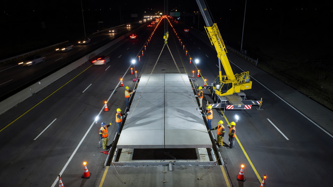
Intermittent PCP repair includes full-depth joint repairs (replacing deteriorated concrete at an existing transverse joint) and full panel replacement (replacing a cracked or shattered slab). Both repairs follow a similar process: the deteriorated concrete is saw-cut and removed; the existing base is inspected, trimmed, and compacted as needed; bedding material is placed or the area is prepared for grout injection; the precast panel is lowered into position using a crane; dowel bars in the panel slots engage with bars in the adjacent pavement; the bedding gap is grouted; and traffic is opened after grout cure (typically 2–4 hours for rapid-setting grout).
Intermittent repairs typically use panels 12 feet long by 12 feet wide (full lane width) with thickness matching the existing pavement. For half-lane repairs, panels may be 6 feet by 12 feet. The FHWA notes that at least four dowel bars should be placed in each wheel path for isolated repairs, with an expansion cap on one end of each bar to accommodate joint movement.
Precast panel fabrication inspection is conducted at the manufacturing plant and covers: concrete material verification — cement type, aggregate gradation, admixture dosage, water-cement ratio, air content, and compressive strength test results (minimum 4,000 psi at 28 days for highway, 5,000 psi for airfield per FAA P-501); reinforcement placement — bar size, spacing, cover, and tie wire integrity; dowel bar alignment — vertical position at mid-depth ± 0.25 inches, horizontal alignment; dimensional checks — length, width, thickness, squareness, surface flatness per FHWA tolerances; and surface finish — texture depth, absence of surface defects (bugholes, honeycombing, cracking).
Each panel is assigned a unique identification number cast into the surface, and fabrication records (concrete batch tickets, curing records, inspection checklists) are maintained for each panel. Panels that fail inspection are marked as rejected and are not shipped to the project site.
Installation inspection covers the following acceptance criteria per FHWA Guide Specification FHWA-HIF-19-017:
| Parameter | Acceptance Criteria | Test Method |
|---|---|---|
| Vertical elevation difference at joints | ≤ 0.06 inches (1.5 mm) | 4-foot straightedge at joint |
| Joint width | 0.25 – 0.5 inches (6–13 mm) | Feeler gauge or caliper |
| Surface smoothness | ≤ 0.125 inches under 10-ft straightedge | Straightedge and feeler gauge |
| Bedding grout coverage | 100 percent of panel area | Verification through vent holes |
| Grout compressive strength | ≥ 3,000 psi at 24 hours | Compressive test of grout samples |
| Dowel bar slot fill | 100 percent fill, no voids | Visual inspection, sounding |
| Panel cracking | None permitted | Visual inspection |
| Spalling at joints | None permitted | Visual inspection |
| Joint sealant | Continuous, no gaps | Visual inspection |
The Engineer (agency representative) must verify that each panel meets these criteria before accepting the installation. Defective panels — those with out-of-tolerance joint elevation differences, cracking, spalling, or grout deficiencies — must be removed and replaced at the contractor’s expense.
Long-term performance inspection of PCP follows the same methodology as conventional concrete pavement inspection per ASTM D5340 (Airport Pavement Condition Index Surveys) or agency pavement management protocols. The specific distresses monitored in PCP include:
Panel Settlement — Differential vertical movement of individual panels relative to adjacent panels or the pavement edge. Settlement is measured using a 4-foot straightedge placed across the joint or a dipstick profiler for continuous profile measurement. Settlement exceeding 0.25 inches at joints is considered a moderate-severity distress requiring corrective action (typically polyurethane injection lifting or partial reconstruction).
Joint Faulting — Vertical elevation difference between the approach and leave sides of a transverse joint. Faulting results from accumulation of incompressible material beneath the leave slab, bedding erosion at the joint, or loss of support. Faulting of 0.1–0.2 inches is the threshold for routine maintenance monitoring; faulting exceeding 0.25 inches requires grinding or slab stabilization.
Bedding Erosion — Loss of bedding material from beneath the panel, detected through Falling Weight Deflectometer (FWD) testing. FWD testing measures the deflection basin under a standardized impulse load — elevated deflection at the joint and reduced load transfer efficiency indicate bedding erosion. FWD testing is performed annually for high-traffic PCP installations and bi-annually for medium-traffic installations.
Dowel Bar Corrosion and Misalignment — Detected through Ground Penetrating Radar (GPR) or Magnetic Imaging Tomography (MIT-Scan) . Corroded or misaligned dowel bars reduce load transfer efficiency and can cause joint spalling and cracking.
Joint Spalling — Breakdown of concrete at the joint edge, typically within 6–12 inches of the joint. Spalling in PCP is most often caused by inadequate slot grouting (voids around dowel bars), dowel bar misalignment (restraining joint movement), or intrusion of incompressible materials into the joint.
Slot Grout Failure — Deterioration or displacement of the grout material in the dowel bar slots, detected through sounding (hollow sound when tapped) or visual inspection (cracking or spalling along slot edges). Slots that have lost grout integrity must be cleaned and re-grouted to restore load transfer.
The FHWA and several state agencies have conducted accelerated pavement testing (APT) of PCP systems to validate performance expectations. The Caltrans accelerated load testing facility tested PCP panels with bottom slots using a heavy vehicle simulator applying 80,000-pound (36,300 kg) equivalent single axle loads (ESALs). Results showed that properly constructed PCP maintained LTE above 80 percent for over 5 million ESALs with no structural cracking.
The Kansas DOT and University of Kansas conducted heavy vehicle simulator testing of jointed precast pavement panels at the Civil Infrastructure Systems Laboratory, applying 100,000-pound axle loads. The testing demonstrated that PCP panels with cementitious bedding maintained LTE above 85 percent after 10 million load applications — equivalent to 30–40 years of interstate highway traffic.
The FHWA reports the following service life expectations for PCP based on field performance data and APT results: intermittent repairs (full-depth joint repairs and single panel replacement) — 20–25 years; continuous JPrCP applications — 30–40 years; and continuous PPCP applications — 40–50 years.
Life-cycle cost analysis comparing PCP to cast-in-place concrete for typical interstate reconstruction: PCP initial construction cost is 15–30 percent higher ($85–$110 per square yard vs. $65–$85 per square yard for cast-in-place); but when user delay costs are included (valued at $25–$50 per vehicle-hour), PCP is typically 10–20 percent lower in total cost because overnight closures eliminate the multi-day traffic disruptions required for cast-in-place construction. The California Department of Transportation estimates that PCP becomes cost-competitive with cast-in-place concrete on routes carrying more than 50,000 vehicles per day in each direction.
Plant fabrication provides the following durability advantages for PCP: consistent water-cement ratio (typically 0.38–0.42 compared to 0.42–0.48 for field concrete); lower permeability (chloride ion penetration 800–1,200 coulombs for plant concrete vs. 1,500–2,500 coulombs for field concrete); higher strength (5,000–8,000 psi plant vs. 4,000–5,500 psi field); better freeze-thaw resistance (durability factor 90–95 percent for plant vs. 80–85 percent for field); and controlled curing eliminating strength variability from weather conditions.
For post-tensioned PCP, the continuous compressive stress (200–400 psi) provides additional durability benefits: the prestress keeps cracks tightly closed (crack width less than 0.004 inches compared to 0.01–0.02 inches for JPCP), preventing water infiltration; the compression at the bottom of the slab reduces tensile stress under traffic loading by 40–60 percent, extending fatigue life; and the elimination of transverse joints (reduced from 440 joints per mile for JPrCP to 10–20 joints per mile for PPCP) removes the primary locations for water ingress and load-related deterioration.
The primary FHWA publications governing PCP design, construction, and inspection include:
| Document Number | Title | Content |
|---|---|---|
| FHWA-HIF-19-017 | Guide Specification for Jointed Precast Concrete Pavement | Comprehensive specification for JPrCP materials, fabrication, installation, and acceptance |
| FHWA-HIF-19-011 | Precast Concrete Pavement Implementation by U.S. Highway Agencies | Case studies and implementation guidance from 29 agencies |
| FHWA-HIF-19-013 | Precast Concrete Pavement Technology Implementation | Final report on SHRP2 Implementation Assistance Program |
| FHWA-HIF-16-008 | Load Transfer Systems for Precast Concrete Pavement | Technical brief on dowel bar design and joint load transfer |
| FHWA-HIF-16-009 | Precast Concrete Pavement Bedding Support Systems | Technical brief on bedding materials and installation |
| FHWA-HIF-019-099 | Overview of Precast Concrete Pavement in the United States | Summary of PCP technology status |
For airfield applications, the primary guidance documents are: AC 150/5370-16 — Rapid Construction of Rigid (Portland Cement Concrete) Airfield Pavements; AC 150/5370-10H — Standards for Specifying Construction of Airports (Item P-501 for PCC Pavements); and AC 150/5380-6C — Guidelines and Procedures for Maintenance of Airport Pavements.
The AASHTO Technical Implementation Group on Precast Concrete Pavement Systems (TIG on PCPS) provides state-level specification guidance and promotes standardized PCP practices across member agencies. The NPCA Manual for Jointed Precast Concrete Pavement (3rd Edition, 2022) is the industry standard reference covering panel design, fabrication quality control, transportation logistics, and installation procedures. The PCI Design Handbook provides structural design standards for precast and prestressed concrete elements.
Beyond standard highway and airfield use, PCP technology has been applied to several specialized scenarios. Bridge approach slabs — where differential settlement between the bridge structure and adjacent pavement creates ride quality problems — benefit from PCP because precast approach slabs can be installed with doweled connections to the bridge abutment and interconnected panels that span the settlement-prone zone. The Colorado DOT constructed a PCP unbonded overlay on I-25 using the proprietary URETEK Stitch-in-Time system (a forerunner of current polyurethane-leveled PCP).
Utility bridges — where failed drainage pipes or culverts pass beneath the pavement — can be repaired using PCP panels designed to span the failed utility structure, distributing traffic loads to stable ground on either side. The panels for this application are reinforced or prestressed to provide the required flexural capacity as a beam spanning the void.
Bus pads and transit stops — where repeated heavy axle loads from buses create rutting in asphalt pavement and spalling in cast-in-place concrete — are a growing application for PCP. The Connecticut DOT installed PCP at two bus pads along the CTfastrak busway in New Britain during October 2016, using 24 bottom-slot panels grout-supported on a prepared base. The bus pads were installed over two overnight closures and opened to bus traffic the following morning, eliminating the months-long closure that would have been required for cast-in-place construction.
PCP panel transportation requires careful logistics planning. Panels are transported from the fabrication plant to the project site on flatbed trailers rated for the panel weight. A typical 12×12 foot highway panel (10 inches thick) weighs approximately 18,000 pounds (8,165 kg) , well within standard heavy-haul truck capacity. Airfield panels measuring 25×12.5 feet and 14 inches thick weigh approximately 45,000 pounds (20,400 kg) , requiring specialized trailers and oversize/overweight permits.
The FHWA Guide Specification requires just-in-time delivery to minimize on-site storage requirements. Panels should arrive at the project site within 3–4 hours of planned installation and be installed within 2 hours of arrival to prevent thermal distortion from differential heating. Panels stored on-site for more than 24 hours must be stored on wooden blocking at 4–6 bearing points per panel, with the blocks placed directly above lifting anchors to prevent bending stresses.
Panel lifting is performed using spreader beams with adjustable lifting points that match the panel’s lifting anchor locations. The spreader beam must be long enough to keep lifting cables at an angle of 60 degrees or more from horizontal to prevent excessive horizontal forces that could crack the panel at the lifting anchors.
Precast concrete pavement systems can reduce runway and taxiway closure times from days to overnight hours while delivering 40-year service life. Our team provides technical guidance on PCP system selection, specification development, and quality assurance inspection for airfield precast pavement projects. Contact us to discuss your rapid pavement repair needs.
Prestressed concrete pavement (PCP) is a rigid pavement system in which internal compressive stresses are introduced into the concrete slab before service loads...
Transverse joints are sawed or formed cuts across PCC pavement slabs at regular spacing (typically 4.5-6 m for JPCP) to control transverse cracking from thermal...
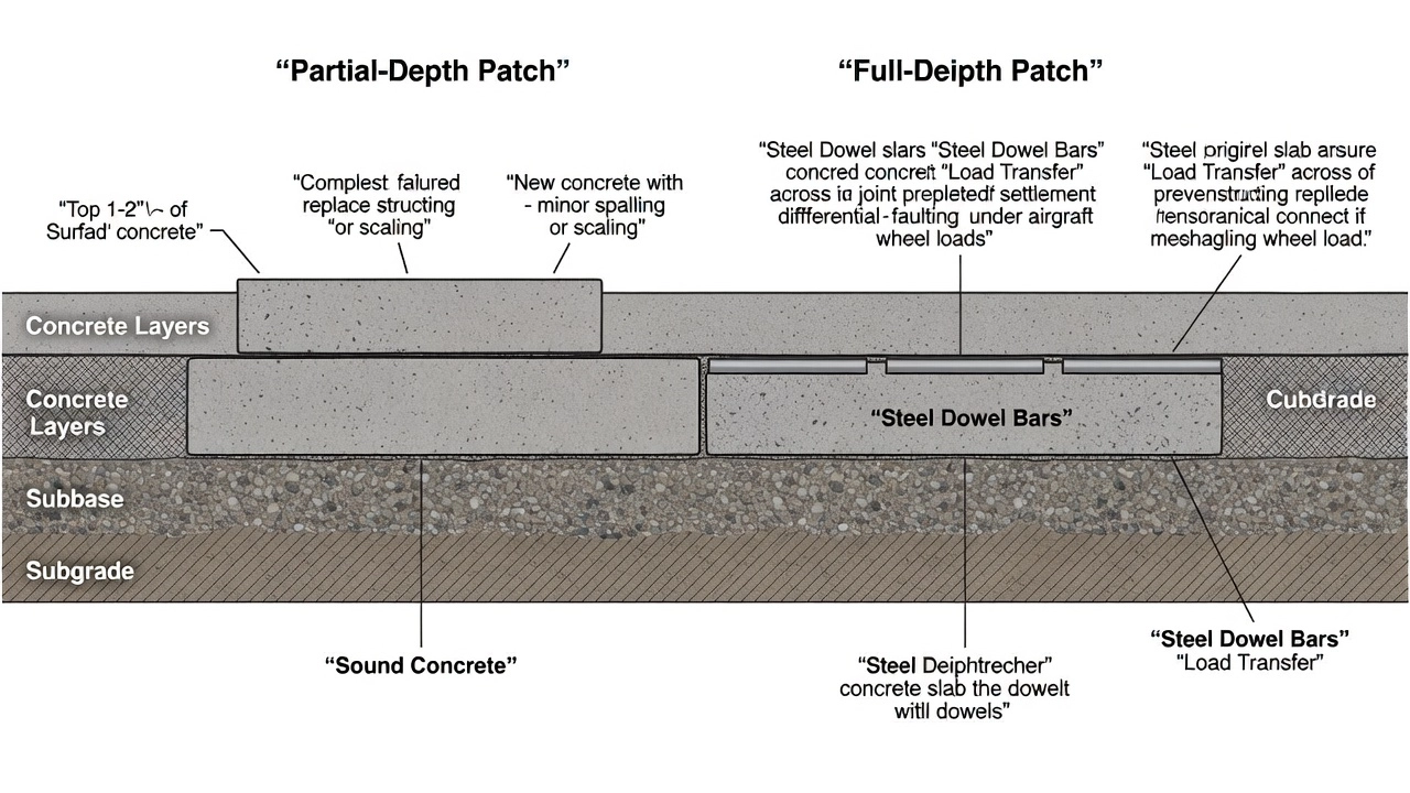
Concrete patching repairs localized PCC distress — partial-depth for surface spalls and scaling, full-depth for corner breaks and shattered slabs. Proper materi...