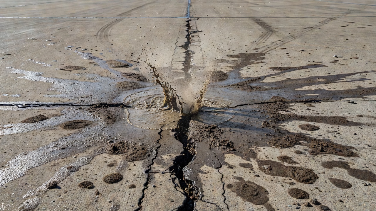
Pumping is the ejection of water and fine subgrade or subbase material through pavement joints, cracks, or edges under passing wheel loads, progressively eroding support and causing faulting and cracking. It is a major deterioration mechanism in PCC pavements.
Definition and Mechanism of Pumping
Pumping is the mechanical ejection of water and suspended fine-grained soil particles from the subgrade, subbase, or base course through pavement joints, cracks, or slab edges, driven by the repeated dynamic deflection of the concrete slab under passing wheel loads. The FHWA Long-Term Pavement Performance (LTPP) Distress Identification Manual formally defines pumping as “the ejection of material by water through joints or cracks, caused by deflection of the slab under passing loads” and classifies it under Distress Type JCP 16 — Water Bleeding and Pumping for jointed portland cement concrete (PCC) pavements, and Distress Type ACP 15 for asphalt concrete-surfaced pavements.
The fundamental mechanism of pumping in rigid pavements follows a well-established sequence. When a heavy wheel load approaches a transverse joint, the approach slab deflects downward under the applied load. If free water is present at the slab-subgrade or slab-subbase interface — typically from rainfall infiltration through unsealed or damaged joints, capillary rise from a high groundwater table, or surface water ponding — the downward deflection pressurizes the trapped water. This pressure forces the water, along with suspended fine soil particles eroded from the subgrade or subbase, through the joint opening and onto the pavement surface. As the wheel load passes and the slab rebounds, a suction effect can draw additional water back into the void, further mobilizing soil particles.
The term “pumping” originated from the analogy to a pump mechanism: the concrete slab acts as the piston, the water trapped between the slab and foundation acts as the working fluid, and the joint opening serves as the discharge valve. Each passing load completes one pump cycle. Research conducted at Purdue University and published by the Joint Highway Research Project defined rigid pavement pumping as “the ejection of water and subgrade, subbase or shoulder material through pavement joints, cracks and edges” and established that the mechanism requires three elements to occur simultaneously: free water, dynamic load, and an expulsion path.
The FHWA Tech Brief on Subbase and Subgrade Erosion (FHWA/TX-09/0-6037-1) notes that “most concrete pavement types will manifest some evidence of pumping if water is present along the interface between the slab and the subbase or subgrade and the subbase or subgrade material is erodible under repeated dynamic loading.” The erodibility of the subgrade or subbase material is a critical factor — fine-grained soils such as silts and clays are most susceptible to pumping because their small particle size allows them to remain suspended in water, while well-graded granular materials with low fines content are generally resistant to pumping.
Hydromechanical Erosion Process
The erosion of subgrade material beneath a concrete slab during pumping is a complex hydromechanical process governed by the interaction of hydraulic pressure, soil mechanics, and cyclic loading. The process can be broken down into four distinct phases that repeat with each wheel load application.
Phase 1 — Slab Deflection and Water Pressurization: As the wheel load approaches the joint, the slab corner or edge deflects downward. The magnitude of deflection depends on slab thickness, concrete modulus of elasticity, subgrade support stiffness (k-value), load magnitude, and the presence or absence of load transfer across the joint. Deflections in pumping-susceptible pavements typically range from 0.25 to 1.0 mm at the slab corner. The downward displacement of the slab reduces the volume available for the water trapped in the interface gap, generating hydraulic pressure. The peak pressure is a function of the deflection rate, water viscosity, and the permeability of the gap between the slab and the subgrade.
Phase 2 — Water Expulsion and Particle Entrainment: The pressurized water seeks the path of least resistance, which is typically the joint opening. As the water flows through the gap toward the joint, it achieves sufficient velocity to entrain fine soil particles from the subgrade surface. The critical shear velocity required to initiate particle motion depends on particle size, density, and cohesion. For typical silt and clay subgrade soils, the critical shear velocity is relatively low, meaning that even moderate hydraulic gradients can initiate erosion. The water- particle mixture is ejected through the joint opening onto the pavement surface, where the fines are deposited as a stain or buildup.
Phase 3 — Cavity Formation and Enlargement: Each pumping cycle removes a small quantity of soil from beneath the slab. Over thousands of load applications, this incremental erosion creates a void or cavity beneath the slab at the joint. The void typically initiates at the slab corner and propagates along the joint. The cavity depth can reach 25 to 50 mm or more in advanced cases. Once a void exists, the slab is no longer uniformly supported, and deflections increase dramatically — a positive feedback loop that accelerates the erosion rate.
Phase 4 — Slab Recovery and Water Inflow: As the wheel load moves past the joint and the slab rebounds, the cavity beneath the slab creates a negative pressure (suction) that draws water back through the joint opening. This replenishes the water supply for the next load cycle. In pavements with poor drainage, the void may remain water-filled between load events, maintaining a constant supply of pressurized water for the next cycle.
The FHWA Distress Identification Manual (Fifth Edition, FHWA-HRT-13-092) emphasizes that pumping in PCC pavements “can occur at cracks as well as joints” and that “surface staining, and base or subgrade material on the pavement close to joints or cracks, are evidence of pumping.” The manual also notes that “no degrees of severity are defined” for pumping — it is sufficient to indicate that the distress exists.
Visual Evidence of Pumping
The visual evidence of pumping on the pavement surface is distinctive and diagnostic. Recognition of these signs during pavement condition surveys is essential for early detection and intervention. The FHWA LTPP Distress Identification Manual and ASTM D6433 (Standard Practice for Roads and Parking Lots Pavement Condition Index Surveys) both provide guidance on identifying pumping.
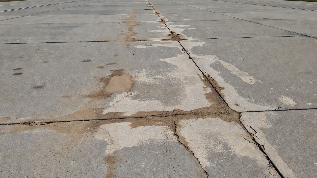
Surface Staining: The most common visual evidence is discoloration or staining of the pavement surface adjacent to joints or cracks. The stain color depends on the type of subgrade or subbase material being ejected. Clay subgrades produce reddish, brownish, or dark stains. Silty subgrades produce light gray or tan stains. Sandy subgrades produce lighter, more granular deposits. The stain pattern typically extends 100 to 500 mm from the joint on both sides, with the heaviest concentration at the joint opening. The staining is often more visible when the pavement surface is dry, as the contrast between the deposited fines and the clean concrete surface becomes more apparent.
Fines Deposition: In active pumping, visible deposits of fine soil material accumulate on the pavement surface at the joint. These deposits may appear as a thin film in early stages or as a buildup of material several millimeters thick in advanced cases. The deposited material can often be wiped away with a finger, revealing the clean concrete surface underneath. During wet weather, the deposited material appears as a muddy slurry around the joint.
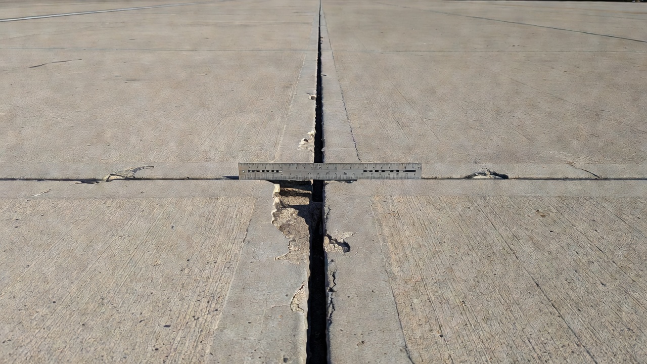
Moisture at Joints:Visible moisture or dampness at joints during dry weather periods indicates that water is present beneath the slab and being forced upward by traffic loads. This is distinct from surface water ponding, which would affect joints uniformly. Pumping-related moisture is typically localized at specific joints where the pumping mechanism is active.
Joint Seal Damage: The joint seal must be identified as defective before pumping can be said to exist, according to the FHWA LTPP definition. This is a critical diagnostic criterion. If the joint sealant is intact and functional, water cannot enter the joint from above, and pumping cannot occur. Therefore, the presence of pumping evidence automatically indicates that the joint sealant is damaged, missing, or has failed. Inspectors should note the condition of joint sealant at pumping-affected joints as part of the distress evaluation.
Associated Distress Evidence: Pumping is rarely an isolated distress. The following associated evidence should be documented during inspection: faulting (measurable vertical displacement across the joint), corner breaks (cracks at approximately 45 degrees from the joint intersection), and settlement of the slab on the leave side of the joint. The FHWA LTPP manual distinguishes pumping from water bleeding, noting that water bleeding is the ejection of clear water without visible soil particles, while pumping involves the ejection of water with suspended fines.
FHWA LTPP Pumping Classification
The FHWA Long-Term Pavement Performance (LTPP) program provides the most widely used standard for pumping classification in pavement condition surveys. The LTPP Distress Identification Manual (DIM), now in its Fifth Edition (FHWA-HRT-13-092, revised May 2014), classifies pumping under both the jointed PCC pavement section and the asphalt concrete pavement section.
For jointed PCC pavements (JCP), pumping is classified as Distress Type JCP 16 — Water Bleeding and Pumping under the Miscellaneous Distresses category (Category D). The measurement units are number of joints or cracks affected and total length in meters of pumping-affected joints. The FHWA manual states that “no degrees of severity are defined” for pumping — the distress is recorded as present or absent. The definition specifically requires that “the joint seal must be identified as defective before pumping can be said to exist.”
Classification Element
LTPP Specification
Distress Type
JCP 16 — Water Bleeding and Pumping
Category
D — Miscellaneous Distresses
Unit of Measure
Number of joints/cracks affected; meters of pumping-affected joints
Severity Levels
None defined
Key Diagnostic Rule
Joint seal must be defective for pumping to exist
Measurement Method
Visual observation during condition survey
The LTPP protocol requires inspectors to distinguish between water bleeding (clear water only, no visible soil particles) and pumping (water with suspended fine particles). In practice, both conditions indicate the presence of water beneath the slab and should be recorded. The manual notes that water bleeding often precedes pumping — once fines begin to appear in the ejected water, subsurface erosion is underway.
For asphalt concrete pavements (ACP), pumping is classified as Distress Type ACP 15 — Water Bleeding and Pumping under the Miscellaneous Distresses category. The definition follows a similar principle: “the ejection of water and fine material from the pavement structure through cracks.” In flexible pavements, pumping is considered a more serious indicator because it typically occurs at advanced stages of fatigue cracking and structural failure.
The LTPP protocol does not require direct measurement of void volume or deflection for pumping classification — visual evidence is sufficient. However, the manual recommends that pumping observations be correlated with wet weather periods, as the distress is most evident during and immediately after rainfall when the subgrade is saturated and pumping activity is at its peak.
Consequences of Pumping
The consequences of unchecked pumping follow a predictable progression from surface staining to structural failure. Understanding this progression is essential for pavement management decisions and prioritization of repairs.
Loss of Support: Each pumping cycle removes fine material from beneath the slab, creating a void or cavity at the slab-foundation interface. The void typically initiates at the slab corner adjacent to the joint and expands along the joint length. The loss of support area can extend 0.3 to 1.0 m from the joint into the slab interior in moderate cases, and across the entire slab width in severe cases. The FHWA notes that loss of support beneath slab corners is the most critical condition because it creates a cantilever-type loading condition at the slab corner, which induces tensile stresses far exceeding those in a uniformly supported slab.
Faulting: Faulting is the vertical differential displacement of the pavement surface across a joint or crack, measured as the difference in elevation between the approach slab and the leave slab. Pumping causes faulting by removing material from beneath the leave slab (the slab on the far side of the joint from the direction of traffic), allowing it to settle relative to the approach slab. Faulting of 3 to 6 mm becomes noticeable to vehicle occupants as a thump or jarring sensation. Faulting exceeding 10 to 13 mm is classified as High severity in the FHWA LTPP system and indicates severe loss of support. Faulting also induces dynamic impact loading that accelerates pavement deterioration and increases vehicle operating costs.
Corner Breaks: As voids develop beneath slab corners, the unsupported slab corner is subjected to repeated tensile stresses under traffic loading that exceed the concrete flexural strength. The result is a corner break — a crack that intersects the transverse and longitudinal joints at approximately 45 degrees (Distress Type JCP 1 in the FHWA LTPP system). Corner breaks are one of the most common structural failures directly attributable to pumping. The FHWA reports that “almost all corner breaks are associated with loss of support” from pumping or subgrade softening.
Transverse and Longitudinal Cracking: As loss of support extends further into the slab interior, transverse mid-slab cracking and longitudinal cracking can develop. These cracks result from curling and warping stresses combined with traffic loads on a slab that is no longer uniformly supported. Once cracked, the slab structure is compromised, and water infiltration through the cracks accelerates the pumping cycle at the crack location.
Load Transfer Deterioration: Pumping progressively reduces load transfer efficiency (LTE) across joints. Load transfer in PCC pavements is achieved through aggregate interlock at the joint faces and through dowel bars where installed. As the void beneath the slab expands, the slab deflections increase, which in turn increases the stress on dowel bars and the abrasive wear on joint faces. Dowel bar loosening can occur, further reducing LTE. Reduced LTE increases slab corner deflections, accelerating the pumping cycle.
Slab Settlement: In advanced pumping cases, the cumulative loss of subgrade material can cause measurable settlement of the entire slab relative to adjacent slabs or the shoulder. This settlement may require grinding or slab replacement to restore ride quality and pavement geometry.
Pumping and Load Transfer Efficiency
The relationship between pumping and load transfer efficiency (LTE) is bidirectional and self-reinforcing. LTE, expressed as a percentage, quantifies the ability of a joint or crack to transfer load from the loaded slab to the unloaded slab. It is measured by the Falling Weight Deflectometer (FWD) as the ratio of the deflection on the unloaded side to the deflection on the loaded side.
LTE = (δ_unloaded / δ_loaded) × 100%
Where δ_unloaded and δ_loaded are the vertical deflections measured on the unloaded and loaded sides of the joint, respectively. An LTE of 70 to 100 percent is generally considered good, 50 to 70 percent is fair, and below 50 percent is poor.
Pumping reduces LTE through three mechanisms. First, the loss of subgrade support beneath the leave slab allows it to deflect more under load, reducing the relative stiffness between the two slabs and diminishing the effectiveness of aggregate interlock. Second, the erosion of the subbase beneath the joint can undermine dowel bar anchorage, reducing their effectiveness. Third, the void at the slab corner concentrates load at the dowel bars, potentially causing dowel bar bending and loosening of the concrete around the dowel.
Conversely, poor LTE accelerates pumping. When LTE is low, the slab on the loaded side of the joint experiences larger deflections. These larger deflections generate higher hydraulic pressures in the water trapped beneath the slab, increasing the erosive force. The FHWA Guide for Load Transfer Restoration (FHWA-HRT-05-064) notes that “a pavement with a structurally adequate slab thickness but a significant loss of load transfer due to lack of dowels, poor aggregate interlock, or loss of support from pumping” is a candidate for load transfer restoration through dowel bar retrofit.
The AASHTO Guide for Design of Pavement Structures accounts for the pumping-LTE interaction in rigid pavement design. The design procedure includes a drainage coefficient and a load transfer coefficient that directly influence the required slab thickness. Pavements with poor drainage (which promotes pumping) require 10 to 30 percent greater slab thickness than well-drained pavements to achieve the same design life.
Pumping in Airport PCC Pavements
Pumping is a specific concern for airport concrete pavements because of the combination of high wheel loads (including multiple-wheel gear configurations on heavy aircraft), high tire pressures, and the operational need for smooth, fault-free surfaces for aircraft operations. The FAA Advisory Circular 150/5320-6G (Airport Pavement Design and Evaluation) directly addresses pumping through its requirements for stabilized base courses and drainage layers beneath rigid airport pavements.
The FAA requires that rigid airport pavements be constructed with a stabilized base course directly beneath the concrete slab. The stabilized base serves multiple functions: it provides a uniform support platform for concrete placement, it prevents the erosion of fine-grained subgrade soils that would cause pumping, and it provides a working platform for construction equipment. The FAA AC 150/5370-10H (Standards for Specifying Construction of Airports) specifies Item P-304 (Cement-Treated Base Course) and Item P-306 (Lean Concrete Base) as acceptable stabilized base materials for rigid pavement construction.
For drainage, the FAA AC 150/5320-6G specifies that “for rigid pavements, generally place a stabilized drainage layer immediately beneath the concrete panel in place of the stabilized base.” The drainage layer is typically a permeable material (such as open-graded granular material or porous concrete) designed to rapidly remove water that enters the pavement structure. The drainage layer is connected to edge drains that convey collected water to an appropriate outlet.
FAA Requirement
Specification
Pumping Prevention Function
Stabilized base (P-304, P-306)
Cement-treated or lean concrete base beneath PCC slab
Rapid water removal; eliminates water at slab interface
Edge drains
Perforated pipe in gravel trench along pavement edge
Collects and removes drainage layer water
Joint sealant
Silicone or preformed compression seal
Prevents water infiltration through joints
Positive cross-slope
1.5-2.0% minimum
Sheds surface water away from joints
Adequate slab thickness
Per FAARFIELD structural design
Minimizes slab deflections under load
The International Civil Aviation Organization (ICAO) Aerodrome Design Manual (Doc 9157, Part 3 — Pavements) emphasizes the importance of drainage in preventing pumping. The manual states that “water trapped in the pavement structure is the primary cause of pumping” and recommends that “the drainage system should be designed to remove water from the pavement structure as rapidly as possible.” ICAO also notes that pumping is a distress condition that can lead to “loss of support, faulting, and cracking” and that “airport pavements showing evidence of pumping should be investigated to determine the extent of subsurface voids.”
The ICAO Airport Services Manual (Doc 9137, Part 2 — Pavement Surface Conditions) includes pumping as a condition to be recorded during airport pavement condition surveys. The manual recommends that pumping be noted on pavement condition survey forms and that the presence of pumping should trigger further investigation, including Falling Weight Deflectometer (FWD) testing to assess void presence and load transfer efficiency.
In airport operations, pumping-related foreign object debris (FOD) from deposited fines is a safety concern. Fine soil particles ejected through joints can be ingested by aircraft engines or abrade propeller blades. The FAA requires airport operators to maintain clean pavement surfaces free of loose material, and pumping deposits must be removed through routine sweeping or washing. However, cleaning the surface does not address the underlying void — it is a cosmetic treatment only.
Detection of Pumping
Detection of pumping combines visual observation, non-destructive testing, and structural evaluation methods. Because pumping is a subsurface phenomenon that manifests surface evidence only after erosion is underway, detection at the earliest possible stage is critical for cost-effective intervention.
Visual Inspection During Wet Weather: The most effective time to detect pumping is during or immediately after rainfall when the subgrade is saturated and pumping activity is at its peak. Inspectors should observe joints and cracks while traffic is passing, looking for evidence of water ejection. The ejected water may appear as a spray or stream emerging from the joint opening. After rainfall, the pavement surface should be examined for staining, fines deposition, and moisture at joints. ASTM D5340 (Standard Test Method for Airport Pavement Condition Index Surveys) and ASTM D6433 (Standard Practice for Roads and Parking Lots Pavement Condition Index Surveys) both include pumping as a distress type to be recorded during PCI surveys.
Falling Weight Deflectometer (FWD) Testing: FWD testing is the primary non-destructive method for detecting voids beneath concrete slabs caused by pumping. The FWD applies a dynamic impulse load (typically 40 to 120 kN for airport pavements) to the pavement surface and measures the resulting deflection using sensors placed at regular spacing from the load plate. The standard FWD test configuration includes sensors at distances of 0, 200, 300, 450, 600, 900, and 1500 mm from the load center. The FAA AC 150/5320-6G Appendix C provides detailed guidance on FWD testing for airport pavement evaluation.
The key FWD indicators of pumping-related voids include:
High deflection at slab corners — deflections at slab corners more than 1.5 to 2 times mid-slab deflections suggest loss of support.
High deflection at the pavement edge — unsupported slab edges deflect more under load than supported edges.
Maximum deflection ratio — the ratio of maximum deflection at the slab corner to the deflection at the first sensor beyond the joint. Ratios exceeding 1.5 indicate potential voids.
Cross-section deflection profile — plotting deflection versus sensor position reveals the shape of the deflection basin. A “reversed” or irregular shape can indicate void presence.
The FHWA Tech Brief on FWD testing notes that “FWD testing that shows areas of high deflection at the edge of a concrete slab may be an indication of a void” and recommends that “voids are generally created below slab corners due to pumping and should be confirmed by coring or other methods.”
Ground Penetrating Radar (GPR): GPR is a non-destructive geophysical technique that uses high-frequency electromagnetic pulses (typically 1.0 to 2.6 GHz antennas for pavement layer evaluation) to image subsurface conditions. GPR can detect voids beneath concrete slabs by identifying:
Gap reflections — a strong reflection from the slab-subgrade interface where a void creates an air gap, producing a high-contrast reflection.
Moisture accumulation — regions of high dielectric constant indicative of water-saturated subgrade.
Layer interface continuity — disruption of the continuous slab-foundation reflection at void locations.
The FAA AC 150/5320-6G Appendix E (Ground Penetrating Radar) provides guidance on GPR use for airport pavement evaluation, noting that GPR “can be used to assess layer thickness, detect voids and moisture, and identify subsurface anomalies.”
Chain Drag Survey: The chain drag method is a simple acoustic technique for detecting delaminated or voided concrete. A heavy steel chain is dragged across the pavement surface while the inspector listens for changes in the sound produced. Sound, intact concrete produces a clear ringing tone. Voided areas produce a hollow, drum-like sound because the air gap beneath the slab allows it to vibrate independently. Chain dragging is effective for detecting larger voids (typically > 0.1 m²) but may miss small, incipient voids.
Core Verification: Definitive confirmation of pumping-induced voids requires concrete core extraction at the suspected location. After extracting the core, an inspection rod or borescope can be inserted into the core hole to visually inspect the void beneath the slab. The depth, extent, and condition of the void can be assessed, and the erodibility of the subgrade or subbase material can be evaluated. Core verification is typically reserved for locations where FWD or GPR testing has indicated potential voids and where the cost of repair justifies the additional investigation.
Prevention of Pumping
Prevention of pumping begins at the design and construction stage and is far more cost-effective than repair. The prevention strategy has six key elements: stabilized base, drainage, joint sealing, adequate thickness, load transfer, and subgrade compaction.
Stabilized Base Course: The most effective single measure to prevent pumping in rigid pavements is the use of a non-erodible stabilized base course between the concrete slab and the subgrade. The stabilized base can be cement-treated base (CTB), lean concrete base (LCB), or asphalt-treated base (ATB). These materials have sufficient cohesion and strength to resist erosion under hydraulic pressures generated by slab deflection. The FAA AC 150/5320-6G requires stabilized base for airport rigid pavements, and the AASHTO Pavement Design Guide includes stabilized base as a means of controlling pumping. For highway pavements, the FHWA recommends a minimum stabilized base thickness of 100 mm to provide adequate erosion resistance.
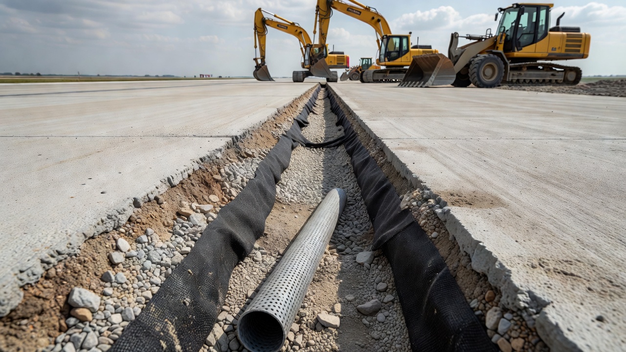
Drainage Layer and Edge Drains: A permeable drainage layer placed beneath the stabilized base (or directly beneath the slab if no stabilized base is used) removes water that enters the pavement structure. The drainage layer consists of open-graded granular material (typically AASHTO No. 57 or No. 67 aggregate) with a minimum permeability of 300 m/day. The drainage layer is connected to edge drains (perforated PVC pipe, typically 100 to 150 mm diameter, wrapped in geotextile fabric) that collect and convey water to an appropriate outlet. The AASHTO design guide specifies that the time required to drain 50 percent of the drainable water should not exceed 10 days for rigid pavements.
Joint Sealant: Effective joint sealant prevents water from entering the joint from the surface. Joint sealants for concrete pavements include silicone sealants (most common for new construction, service life 10-15 years), hot-poured rubberized asphalt (service life 5-8 years), and preformed compression seals (service life 10-20 years). The FHWA LTPP definition explicitly states that the joint seal must be defective for pumping to exist, highlighting the critical role of sealant maintenance. Routine joint sealant inspection and replacement is a cost-effective preventive maintenance activity.
Adequate Slab Thickness: Thicker slabs deflect less under load, reducing the hydraulic pressures that drive pumping. The AASHTO Guide for Design of Pavement Structures explicitly includes pumping as a design consideration through the drainage coefficient (Cd) and load transfer coefficient (J). Pavements with lower drainage quality (which increases pumping risk) require higher slab thickness to compensate. The FAA FAARFIELD pavement design software accounts for the effect of stabilized base and drainage on pavement performance and allows the designer to optimize the slab-base-drainage system to minimize pumping risk.
Load Transfer:Dowel bars at transverse joints improve load transfer and reduce slab deflections, which reduces the hydraulic pressures that drive pumping. The FAA AC 150/5320-6G specifies dowel bar diameter and spacing based on slab thickness. For airport pavements, commonly used dowel bars are 32 mm diameter (1.25 inches) spaced at 300 mm. For highway pavements, typical dowels are 32 to 38 mm diameter spaced at 300 mm. Proper dowel bar placement (within ±25 mm of the slab mid-depth) and alignment (within ±12 mm per 450 mm of bar length) are essential for effective load transfer.
Subgrade Compaction: Adequate subgrade compaction provides a denser, more erosion-resistant foundation. The FAA requires compaction to at least 95 percent of maximum dry density (ASTM D698 or AASHTO T 99) for subgrade beneath rigid airport pavements. The top 150 mm of subgrade should be compacted to at least 100 percent of maximum dry density. Uniform compaction prevents differential support conditions that concentrate deflections at isolated locations.
Repair of Pumping-Affected Pavements
When pumping has already occurred, repair focuses on restoring slab support, filling subsurface voids, and preventing water re-entry. The primary repair method is slab stabilization, also known as undersealing, subsealing, or pressure grouting.
Slab Stabilization (Undersealing): Slab stabilization involves drilling holes through the concrete slab (typically 12 to 19 mm diameter, spaced at 1 to 1.5 m intervals in the pumping-affected area) and injecting a flowable material under pressure to fill the voids created by pumping. The injected material restores uniform support to the slab, reducing deflections and preventing further erosion. The FHWA Slab Stabilization Guidelines (FHWA-HIF-20-058) define slab stabilization as “a nondestructive, void-filling, corrective process that restores slab support.”
Three types of injection materials are commonly used:
Material Type
Composition
Application
Advantages
Limitations
Cementitious grout
Portland cement, water, sometimes fly ash or sand
Standard slab stabilization
High strength, low cost, widely available
Shrinkage possible, longer cure time
Polyurethane foam
Two-component expanding polyurethane
Rapid stabilization, lifting slabs
Low viscosity fills small voids, expands, rapid strength gain (<15 min)
Higher cost, temperature sensitive
Asphalt-based grout
Emulsified asphalt or asphalt cement
Flexible pavements, moisture areas
Good adhesion, waterproof, flexible
Temperature dependent, lower strength
The injection pressure is critical — it must be sufficient to force the grout into the void (typically 140 to 345 kPa or 20 to 50 psi) but not so high as to lift or fracture the slab. Continuous monitoring of both pressure and slab lift is essential during injection. The FHWA recommends that “injection should stop when the slab begins to lift, when grout returns through adjacent holes, or when the specified maximum pressure is reached.”
Post-Stabilization Verification: After slab stabilization, FWD testing should be repeated to verify that deflections have been reduced to acceptable levels. A post-stabilization deflection reduction of at least 50 percent at the slab corner is considered successful. If deflections remain high, additional injection holes may be required. The injected material should be allowed to cure (typically 24 to 72 hours for cementitious grout, 15 to 30 minutes for polyurethane foam) before the pavement is opened to traffic.
Fault Correction: If pumping has caused faulting exceeding 3 to 5 mm, the fault should be corrected after slab stabilization. Diamond grinding is the standard method for fault correction — a grinding head with diamond-impregnated blades passes over the joint to create a smooth, continuous surface across the fault. The grinding depth is typically 3 to 10 mm and extends 0.5 to 1.0 m on each side of the joint. Grinding restores ride quality and reduces dynamic impact loading.
Joint Sealant Replacement: After slab stabilization, all pumping-affected joints should be resealed to prevent water re-entry. The existing sealant should be removed, the joint reservoir cleaned and dried, and new sealant installed. For pavements with a history of pumping, consideration should be given to upgrading the sealant type to a longer-lasting silicone or preformed compression seal.
Drainage Improvements: If the drainage system is found to be inadequate, edge drains or underdrains should be installed as part of the repair. The drainage improvements address the root cause of pumping — water presence in the pavement structure. Retrofit edge drain installation involves trenching along the pavement edge to a depth below the slab-subgrade interface, installing perforated pipe wrapped in geotextile, backfilling with permeable aggregate, and connecting to an adequate outlet.
Full-Depth Slab Replacement: In severe cases where pumping has caused extensive cracking, corner breaks, or faulting exceeding 10 to 13 mm, full-depth slab replacement may be necessary. The replacement slab should be constructed with a stabilized base, dowel bars at transverse joints, and proper joint sealant to prevent recurrence of pumping. The FAA and FHWA full-depth repair guidelines specify minimum patch size (typically the full lane width and at least 3.6 m length), dowel bar requirements, and curing procedures.
Pumping in Flexible (Asphalt) Pavements
While pumping is most commonly associated with rigid PCC pavements, it also occurs in flexible asphalt pavements (Distress Type ACP 15 in the FHWA LTPP Distress Identification Manual). The mechanism differs from rigid pavement pumping because asphalt concrete does not have joints that serve as direct expulsion paths.
In flexible pavements, pumping occurs when water enters the pavement structure through surface cracks (typically fatigue cracking, longitudinal cracking, or edge cracking) and accumulates on top of the subgrade or unbound base. Under heavy traffic loads, the flexible pavement structure deflects, pressurizing the trapped water. The water, carrying suspended fine particles from the subgrade or base, is forced back through the surface crack and ejected onto the pavement surface.
The critical difference between flexible and rigid pavement pumping is the origin of the fines. In rigid pavements, the fines come from the subgrade or subbase directly beneath the slab. In flexible pavements, the fines can come from either the unbound base course or the subgrade. The appearance of fines on the asphalt surface indicates that the base or subgrade has been eroded and weakened.
The LTPP Distress Identification Manual describes pumping in flexible pavements as “the ejection of water and fine material from the pavement structure through cracks.” The manual notes that “pumping may also be accompanied by surface cracking, rutting, and loss of support” and that “continued pumping can lead to the development of potholes.”
Pumping in flexible pavements is considered a more advanced stage of distress than pumping in rigid pavements. The appearance of pumping in an asphalt pavement indicates that:
The pavement structure has undergone significant fatigue damage
Cracks have penetrated the full pavement thickness
Water has accumulated in the pavement structure
The subgrade or base has been weakened by moisture
The pavement structure has lost load-carrying capacity
Repair of pumping in flexible pavements typically requires structural overlay or reconstruction rather than localized repair. The pumping-affected area has typically lost significant structural capacity, and a thin overlay would not address the loss of foundation support. The recommended repair strategy involves removing the deteriorated pavement in the affected area, addressing the drainage deficiency, compacting or replacing the weakened subgrade or base, and placing a structural overlay of adequate thickness to prevent recurrence.
Pumping, Subgrade Erosion, and the AASHTO Design Method
The AASHTO Guide for Design of Pavement Structures explicitly accounts for pumping through the drainage coefficient (Cd) and the load transfer coefficient (J) in the rigid pavement design equation. These coefficients directly influence the required slab thickness and represent the empirical recognition that pumping is a primary failure mechanism for rigid pavements.
The drainage coefficient (Cd) ranges from 0.70 (for pavements with poor drainage, where water is removed slowly) to 1.25 (for pavements with excellent drainage, where water is removed rapidly). The AASHTO guide defines drainage quality in terms of the time required to remove 50 percent of the free water from the pavement structure. Pavements with drainage requiring more than 1 month to remove 50 percent of water are classified as “poor” drainage (Cd = 0.70-0.80), while those draining in less than 2 hours are classified as “excellent” (Cd = 1.20-1.25).
The selection of the drainage coefficient directly reflects pumping risk. Pavements in wet climates with erodible subgrades require lower Cd values (higher slab thickness), while pavements in dry climates with stabilized bases can use higher Cd values (lower slab thickness). The AASHTO design equation is:
ΔPSI = difference between initial and terminal serviceability
p_t = terminal serviceability
S_c = concrete modulus of rupture
C_d = drainage coefficient
J = load transfer coefficient
E_c = concrete modulus of elasticity
The load transfer coefficient (J) ranges from 2.5 (for PCC pavements without dowels and without tied shoulders, typical of pumping-affected conditions) to 3.2 (for PCC pavements with dowels and tied concrete shoulders, representing good load transfer). Higher J values indicate better load transfer and reduced slab corner deflections, which directly reduces pumping potential.
Summary of Key Design and Inspection Parameters
Parameter
Value/Range
Relevance to Pumping
Slab thickness (airport, rigid)
250-500 mm (10-20 in)
Thicker slabs reduce deflections and pumping pressure
Longer spacing increases deflections and pumping risk
Subgrade compaction
≥ 95% max dry density
Denser subgrade resists erosion
Cross-slope (airport)
1.5-2.0%
Positive slope removes surface water
FWD corner deflection threshold
> 0.5-1.0 mm
Indicates possible void presence
LTE threshold for intervention
< 70%
Poor load transfer accelerates pumping
The relationship between these parameters and pumping demonstrates that effective pumping prevention requires an integrated design approach. No single element — not even a stabilized base — can fully prevent pumping if other elements are deficient. A pavement with good base and thickness but poor drainage will still pump under wet conditions. Conversely, a pavement with excellent drainage but no stabilized base can pump if the subgrade is erodible and water enters through defective joints.
Understanding pumping as a system-level interaction between loads, water, foundation, and pavement structure is essential for both design and forensic evaluation. When pumping is observed during a PCI survey, the inspector or pavement engineer should evaluate not only the immediate distress but also the contributing factors: joint sealant condition, drainage adequacy, subgrade type, load transfer condition, and traffic loading history. This comprehensive evaluation informs both immediate repair decisions and long-term pavement management planning.
Frequently Asked Questions
Pumping requires three simultaneous conditions: (1) free water present at the interface between the concrete slab and the underlying subgrade or subbase, (2) a dynamic wheel load of sufficient magnitude to deflect the slab and pressurize the water, and (3) a joint, crack, or slab edge opening through which the pressurized water can escape. The water carries fine soil particles (silts, clays, or fine sands) from the subgrade or subbase in suspension. With each passing load, more material is ejected, progressively enlarging the subsurface void. The mechanism is most active during wet weather periods when the subgrade is saturated. Inadequate joint sealing, poor drainage, and erodible subbase materials significantly accelerate the process.
The primary visual evidence of pumping includes surface staining near joints and cracks, typically lighter in color (tan, gray, or whitish) than the surrounding concrete, caused by the deposited fines ejected from below. In advanced cases, a buildup of fine material is visible on the pavement surface extending outward from the joint or crack. The surface around the joint may show moisture or dampness during and immediately after rainfall. Water may be seen being ejected from joints under passing heavy vehicles. Joint sealant is typically damaged or missing, allowing the free passage of water. The area adjacent to the pumping joint often shows evidence of slab settlement or faulting. Dark, muddy staining indicates active pumping of clayey subgrade soils.
Water bleeding (Distress Type JCP 16 in the FHWA LTPP manual, grouped together with pumping) refers specifically to the ejection of clear water from joints or cracks without visible soil particles. Pumping involves the ejection of water containing suspended fine particles from the subgrade or subbase. In the LTPP Distress Identification Manual, water bleeding and pumping are classified under the same distress type (JCP 16), with pumping defined as the ejection of water and subgrade material, while water bleeding is the ejection of clear water only. From a practical standpoint, water bleeding indicates the presence of free water beneath the slab — a necessary precondition for pumping — and should be considered a warning sign that pumping may develop if the subgrade is erodible under continued traffic loading.
Pumping is detected through visual inspection of the pavement surface during wet weather or immediately after rainfall. The inspector looks for staining, fines deposition, moisture at joints, and evidence of water ejection. The FHWA LTPP Distress Identification Manual specifies that pumping is recorded in terms of the number of affected joints and cracks and the total length of pumping-affected joints in meters. No severity levels are defined — it is sufficient to indicate that pumping exists. Advanced detection methods include Falling Weight Deflectometer (FWD) testing, where high deflections at slab corners and edge locations indicate voids beneath the slab. Ground Penetrating Radar (GPR) can identify subsurface voids and moisture accumulation. Dynamic cone penetrometer (DCP) testing can assess subgrade strength loss in affected areas.
Untreated pumping leads to a cascading series of pavement failures. The loss of subgrade or subbase material creates voids beneath the slab, reducing support. With reduced support, slab deflections increase under traffic loading, accelerating the erosion process. The slab begins to fault — one side of the joint settles relative to the other, creating a vertical step that causes roughness and dynamic impact loading. Increased slab deflections induce tensile stresses at the slab corners, leading to corner breaks (cracks that intersect the transverse and longitudinal joints at approximately 45 degrees). In advanced cases, the loss of support can cause transverse mid-slab cracking and eventual slab cracking into multiple pieces. Load transfer efficiency across joints deteriorates, further concentrating stresses at joint edges. The pavement ultimately requires full-depth slab replacement rather than less costly maintenance interventions.
Prevention of pumping begins at the design and construction stage. Key measures include: (1) using a non-erodible stabilized base course (cement-treated or lean concrete base) beneath the concrete slab — the FAA AC 150/5320-6G requires stabilized base for rigid airport pavements; (2) incorporating a drainage layer or permeable subbase with edge drains to remove water from beneath the slab; (3) providing positive pavement cross-slope (1.5-2.0 percent) to shed surface water; (4) installing effective joint sealant to prevent water infiltration into the joint; (5) ensuring adequate subgrade compaction; (6) using dowel bars at transverse joints to improve load transfer and reduce slab deflections; and (7) designing adequate slab thickness to minimize deflections under design traffic loads. The AASHTO Pavement Design Guide explicitly requires pumping evaluation for rigid pavement design.
Repair of pumping-affected pavements focuses on restoring slab support and preventing further erosion. The primary repair method is slab stabilization (also called undersealing or subsealing), which involves drilling holes through the concrete slab and injecting a flowable grout material (typically cementitious grout, polyurethane foam, or asphalt-based material) under pressure to fill the voids created by pumping. The grout fills the void space and restores uniform support to the slab. After stabilization, damaged joints should be resealed to prevent water re-entry. For slabs that have already faulted, diamond grinding can restore ride quality by smoothing the vertical step at the joint. In severe cases where faulting exceeds approximately 6-10 mm or the slab has cracked, full-depth slab replacement may be necessary, with installation of dowel bars for load transfer and a stabilized base to prevent recurrence.
Yes, pumping can occur in flexible asphalt pavements, although the mechanism differs from rigid PCC pavements. In flexible pavements, pumping involves the ejection of fine material from the subgrade or unbound base through the pavement surface under heavy traffic loads. The water and fines typically emerge through surface cracks, along pavement edges, or through permeable areas of the asphalt. Pumping in flexible pavements is classified as Distress Type ACP 15 in the FHWA LTPP Distress Identification Manual. The mechanism is typically associated with fatigue cracking that allows water infiltration, combined with a saturated subgrade and heavy truck traffic. In asphalt pavements, pumping is a strong indicator of structural failure, as the water and fines emerging from the pavement indicate that the subgrade or base has been weakened and that the pavement structure has lost its load-carrying capacity. Repair typically requires reconstruction or overlay with improved drainage.
Joint sealant condition is critical to pumping development. The FHWA LTPP Distress Identification Manual explicitly states that 'the joint seal must be identified as defective before pumping can be said to exist.' This is because effective joint sealant prevents water from infiltrating the joint and reaching the slab-foundation interface. When sealant is intact, the amount of water that can reach the subgrade through sound concrete is minimal. When sealant is damaged, missing, or hardened, the joint becomes a direct channel for water to enter the pavement structure. During wet weather, water flows into the open joint, accumulates on top of the subgrade or base, and becomes available for pumping when traffic loads deflect the slab. Routine joint sealant inspection and replacement (typically every 5-10 years depending on sealant type and climate) is one of the most cost-effective pavement preservation activities to prevent pumping.
Improve your airport pavement inspection
TarmacView provides AI-powered pavement inspection solutions that automatically detect and classify distresses like pumping, faulting, and joint deterioration in concrete airport pavements. Schedule a demonstration to see how our technology can enhance your pavement management program.
Joint spalling is the cracking, breaking, or chipping of concrete slab edges at transverse or longitudinal joints in PCC pavements. It occurs when incompressibl...
A punchout is a localized structural failure in continuously reinforced concrete pavement (CRCP) where two closely spaced transverse cracks intersect with a lon...
Faulting at Joints and Cracks in Concrete Pavements
Faulting is the vertical displacement at a transverse joint or crack in concrete pavement, creating a 'step' felt by vehicles crossing the joint. It results fro...
27 min read
Pavement defects
Concrete pavement
+2
Cookie Consent We use cookies to enhance your browsing experience and analyze our traffic. See our privacy policy.