A punchout is a localized structural failure in continuously reinforced concrete pavement (CRCP) where two closely spaced transverse cracks intersect with a longitudinal crack or pavement edge, forming loose broken concrete pieces. It is the terminal distress mechanism for CRCP.
Definition and Formation Mechanism
A punchout is the terminal structural distress unique to continuously reinforced concrete pavement (CRCP). It is defined by the FHWA Long-Term Pavement Performance (LTPP) program as a localized area of broken concrete pavement where two closely spaced transverse cracks—typically less than 0.6 m (2 ft) apart—intersect with a longitudinal crack or the pavement edge, creating an isolated piece of pavement that punches or settles downward under traffic loading. The punchout distress is widely regarded as the most severe performance-related problem that CRCP pavements develop, as it represents a complete structural failure of the pavement section.
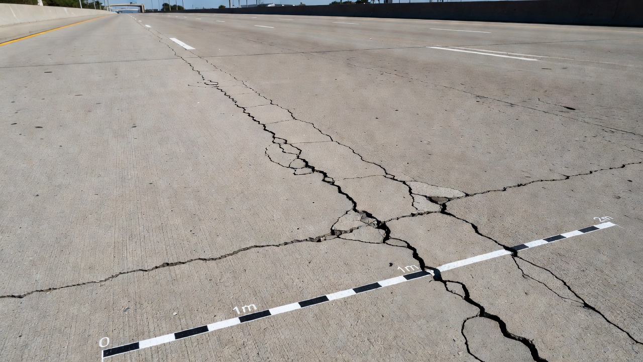
The formation mechanism of a punchout follows a well-documented sequence. It begins with the loss of aggregate interlock at one or two transverse cracks that are closely spaced (usually less than 1.22 m or 48 in apart). Transverse cracks in CRCP are intentionally designed features—the continuous steel reinforcement (typically 0.6% to 0.7% by cross-sectional area) induces a controlled pattern of closely spaced cracks (0.5 to 1.8 m or 1.5 to 6 ft spacing) that are held tightly closed. These cracks rely on aggregate interlock for load transfer between adjacent concrete sections. As the crack width increases due to environmental cycling (thermal expansion and contraction, moisture-related curling and warping) and repeated traffic loads, the aggregate interlock degrades. The load transfer efficiency, measured as the ratio of deflection on the loaded side to the unloaded side of a crack, decreases from typical values of 80–90% in sound CRCP to below 50% in deteriorating sections.
Once load transfer is compromised, the portion of slab between two closely spaced deteriorated cracks begins to act as an isolated structural element—essentially a cantilever beam supported at the crack locations. Heavy traffic loading induces high tensile stresses at the top of the slab. Research by Darter, LaCoursiere, and Smiley (1979) demonstrated that these tensile stresses reach maximum values approximately 0.6 to 1.5 m (24 to 60 in) from the pavement edge. Under continued traffic, a short longitudinal fatigue crack forms between the two transverse cracks at this critical stress location. This longitudinal crack completes the isolation of a concrete panel, bounded by two transverse cracks on either end and a longitudinal crack or pavement edge on the side.
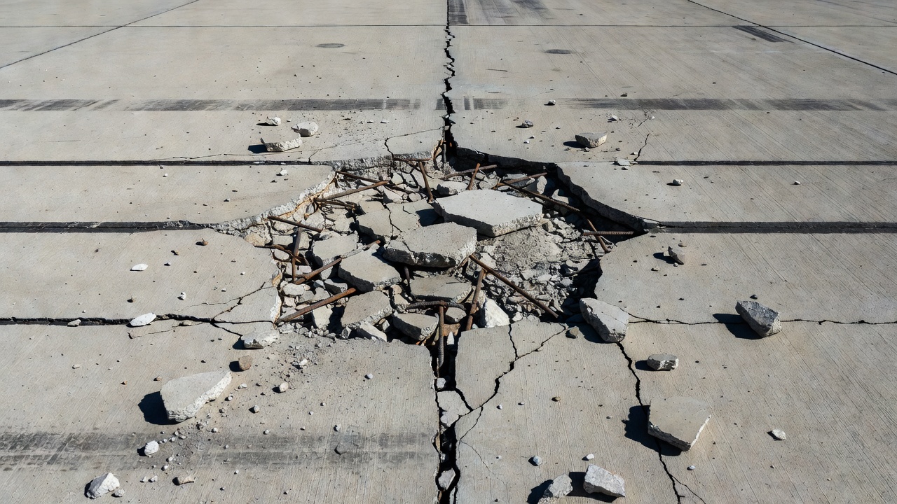
With subsequent wheel loads, the isolated panel punches downward into the subbase and subgrade. This downward movement produces faulting (vertical elevation difference) across the cracks, further spalling of the concrete at the crack edges, and eventual steel rupture as the reinforcing bars are subjected to tensile forces beyond their capacity. The entire process results in a localized area of broken, loose concrete that poses a serious safety hazard to both vehicular and aircraft traffic. Left unrepaired, the distressed area expands to adjacent transverse cracks, progressively enlarging the failure zone.
Research by Zollinger and Barenberg (1990) on Illinois CRCP pavements identified that pumping of the subbase material is nearly always associated with punchout development. The cyclic deflection of the slab under traffic loads pumps water and fine erodible base particles out from beneath the slab, creating voids and accelerating the loss of foundation support. This pumping action manifests as stained surface deposits near cracks and joints, visible evidence of the ongoing deterioration mechanism.
Distinction from Corner Breaks and Shattered Slabs
Punchouts must be distinguished from other concrete pavement distress types that may appear visually similar, particularly corner breaks and shattered slabs. Each distress type has distinct definitions, formation mechanisms, and implications for pavement management.
A corner break is a crack that intersects two adjacent joints near the corner of a slab, with the crack intercepting each joint at a distance less than or equal to half the slab length on both sides. For example, in a 3.5 m × 6 m (11.5 ft × 20 ft) slab, a crack that intersects 1.2 m (4 ft) on one side and 2.4 m (8 ft) on the other qualifies as a corner break. The crack extends vertically through the entire slab thickness. Corner breaks are caused by load repetition combined with loss of support and curling stresses. They are not the same as corner spalls, which intersect the joint at an angle rather than vertically through the slab. Corner breaks occur in jointed concrete pavements (JPCP and JRCP), not CRCP, because CRCP has no transverse contraction joints for corner breaks to intersect.
A shattered slab (also called divided slab) is a slab broken into four or more pieces due to overloading and/or inadequate support. In the PAVER distress identification system, shattered slabs are classified separately from punchouts. If all pieces or cracks are contained within a corner break, the distress is categorized as a severe corner break rather than a shattered slab. Shattered slabs can occur in any concrete pavement type including CRCP, but the key distinction from punchouts is that shattered slabs involve the entire slab area being broken into multiple pieces by any combination of crack patterns, whereas punchouts are specifically defined by the bounding geometry of two closely spaced transverse cracks and a longitudinal crack.
The fundamental distinguishing characteristic of a punchout is its crack geometry: the failure zone is bounded on two sides by transverse cracks (spaced less than 1.5 m or 5 ft apart per ASTM D6433) and on the third side by a longitudinal crack or pavement edge. This geometry is unique to CRCP because continuous longitudinal steel eliminates joints and produces the characteristic transverse crack pattern. The punchout essentially represents a structural failure of the concrete panel between two closely spaced cracks that were too close together to develop adequate aggregate interlock and load transfer capabilities.
The PAVER manual provides clear guidance: if a slab has linear cracking dividing it into two or three pieces, it is not a punchout. If a slab is divided into four or more pieces by general cracking patterns, it is a shattered slab. Only when the distress exhibits the characteristic transverse-crack-bounded geometry with an associated longitudinal crack is it classified as a punchout. This distinction is critical for selecting the correct repair strategy.
FHWA LTPP Classification
The FHWA Long-Term Pavement Performance (LTPP) program established standardized protocols for classifying punchout distress severity as part of the General Pavement Study-5 (GPS-5) experiment, which monitored 85 CRCP test sections across 29 states in four climatic regions. The LTPP classification system evaluates punchout severity based on two variables: the severity of the majority of cracks bounding the punchout, and the number of broken pieces within the distressed area.
The severity classification matrix for punchouts is as follows:
Severity of Majority of Cracks
Slab in 2–3 Pieces
Slab in 4–5 Pieces
Slab in More than 5 Pieces
Low
Low (L)
Low (L)
Medium (M)
Medium
Low (L)
Medium (M)
High (H)
High
Medium (M)
High (H)
High (H)
Low severity (L) punchouts are characterized by a slab broken into 2 to 3 pieces with low severity cracks (non-filled cracks less than 13 mm or 0.5 in wide; filled cracks of any width with filler in satisfactory condition; no faulting). The area between the bounding cracks may be lightly cracked but is essentially intact. Low severity punchouts indicate early-stage distress where the concrete pieces are still relatively tight and load transfer, though reduced, is partially maintained.
Medium severity (M) punchouts represent intermediate deterioration where either the slab contains 2 to 3 pieces with high severity cracks, or 4 to 5 pieces with medium severity cracks. Medium severity cracks are defined as non-filled cracks 13 to 50 mm (0.5 to 2 in) wide, or cracks of any width with faulting less than 10 mm (0.375 in). At medium severity, the punchout area shows visible settlement, the concrete pieces are loose, and steel may be exposed but not necessarily ruptured.
High severity (H) punchouts represent terminal distress where either the slab contains 4 to 5 pieces with high severity cracks, or more than 5 pieces at any crack severity. High severity cracks are non-filled cracks wider than 50 mm (2 in) or any crack with faulting exceeding 10 mm (0.375 in). High severity punchouts exhibit significant settlement, extensive spalling, exposed and often ruptured reinforcing steel, and loose debris that creates an immediate safety hazard. These punchouts require urgent full-depth repair to prevent vehicle damage and safety incidents.
The LTPP GPS-5 data analysis, published in 2002 by the Concrete Reinforcing Steel Institute, showed that punchout distress was strongly correlated with slab thickness. Sections with 203 mm (8 in) slabs showed significantly more punchouts per kilometer than sections with 229 mm (9 in) or greater thickness. The analysis also demonstrated that punchout frequency increased linearly with accumulated 80 kN (18 kip) equivalent single-axle loads (ESALs). Sections with 0.62% or less longitudinal reinforcement showed higher punchout rates than sections with greater steel content.
Causes
The development of punchout distress in CRCP is driven by multiple interacting factors. Understanding these causes is essential for both design optimization and maintenance planning.
Loss of Foundation Support
Loss of support beneath the CRCP slab is the single most significant factor in punchout development. Field investigations by Zollinger and Barenberg (1990) on Illinois CRC pavements found that punchouts were invariably accompanied by severe subbase erosion and loss of support. This loss occurs through several mechanisms. Pumping of erodible base materials under repeated traffic loads removes fine particles from beneath the slab, creating voids that leave the concrete unsupported. Water infiltration through cracks and joints accelerates this process by pressurizing the water-saturated base under traffic loads. The presence of free water combined with heavy wheel loads produces hydrodynamic pressures that erode even stabilized base materials over time. Subgrade softening from moisture accumulation further reduces the effective modulus of subgrade reaction (k-value), increasing slab deflections and accelerating the distress cycle.
Research from the Mechanistic-Empirical Pavement Design Guide (MEPDG) development showed that loss of support along the pavement edge is particularly critical. Edge support conditions directly control the magnitude of critical tensile stresses in CRCP. Sections with tied concrete shoulders showed significantly lower punchout rates compared to sections with asphalt shoulders, because the tied shoulder provides continuous load transfer and prevents edge deflection.
Steel Corrosion
Corrosion of the longitudinal reinforcing steel is a major contributing factor to punchout development, particularly in regions where deicing salts are used. Chloride ions penetrate the concrete through the natural transverse crack network, reaching the steel reinforcement and initiating corrosion. The corrosion process produces expansive corrosion products (rust) that generate tensile stresses within the concrete, leading to horizontal cracking at the depth of the reinforcement plane. This horizontal cracking, also called delamination or D-cracking in the steel plane, weakens the concrete section and accelerates the loss of aggregate interlock.
The FHWA research report on CRCP early-age behavior notes that corrosion also reduces the effective cross-sectional area of the steel reinforcement, increasing stress in the remaining steel and potentially leading to premature steel rupture. In advanced stages, corrosion-induced cracking creates a plane of weakness at the steel depth, allowing the top portion of the slab to separate from the bottom portion in a mechanism known as top-down delamination.
Fatigue Loading
Repeated heavy traffic loads produce fatigue damage in both the concrete and the steel reinforcement. The CRCP slab between closely spaced cracks flexes under each wheel pass, generating tensile stresses at the top surface and compressive stresses at the bottom. The magnitude of these stresses depends on the crack spacing, crack width, slab thickness, and foundation support conditions. Finite element analyses performed during the NCHRP 1-37A project demonstrated that the critical tensile stress at the top of the slab increases dramatically as crack spacing decreases below 0.6 m (2 ft).
Traffic loads also contribute to progressive deterioration of aggregate interlock through shear fatigue at the crack faces. Each load repetition causes micro-damage to the exposed aggregate particles at the crack interface, gradually wearing down the interlock mechanism. This fatigue process is captured in the load transfer efficiency (LTE) deterioration models used in the MEPDG. The models predict that LTE decreases as a function of both the number of load repetitions and the crack width, with wider cracks experiencing faster deterioration.
Crack Width
Crack width is the most critical parameter influencing punchout development in the MEPDG framework. Research by Moharekpour, Liu, and Oeser (2022) demonstrated that crack width directly controls the rate of load transfer deterioration and punchout formation. Wider cracks provide less aggregate interlock because the separation between crack faces reduces the physical interlocking of aggregate particles. The relationship between crack width and LTE is approximately exponential: a crack width increase from 0.5 mm to 2.0 mm can reduce LTE from 85% to below 40%.
Crack width in CRCP is influenced by the steel reinforcement content (percent steel), the concrete thermal coefficient of expansion, the temperature at the time of construction, and the climatic conditions over the pavement life. Sections constructed during hot weather typically develop wider cracks during subsequent cold weather contraction. The design objective for CRCP is to maintain crack widths below 0.5 mm (0.02 in) through adequate steel reinforcement (typically 0.6% to 0.7% of cross-sectional area). When crack widths exceed this threshold, the risk of punchout development increases substantially.
Other Contributing Factors
Additional factors identified through LTPP data analysis and field studies include: inadequate slab thickness (punchout rates are 3–5 times higher in 203 mm slabs compared to 254 mm slabs at equivalent traffic levels); construction defects such as honeycombing, improper lapping of reinforcement, or poor consolidation at construction joints; base erodibility (cement-treated and lean concrete bases show lower punchout rates than granular bases); drainage conditions (sections with poor drainage exhibit punchout rates 2–4 times higher than sections with good drainage); and cluster cracking where multiple closely spaced cracks create a zone of weakened pavement.
Punchout in Airport CRCP Pavements
Airport pavements constructed as CRCP are particularly susceptible to punchout distress due to the heavy loads, high tire pressures, and concentrated traffic patterns characteristic of aircraft operations. The FAA Advisory Circular AC 150/5370-10H (Standard Specifications for Construction of Airports) provides specifications for CRCP construction on airfields, including requirements for steel reinforcement content, slab thickness, and base materials. The FAA also mandates annual Pavement Condition Index (PCI) surveys per AC 150/5380-7B, which identify and quantify punchout distress as part of the overall pavement condition assessment.
Airport CRCP pavements are designed for higher load magnitudes than highway CRCP. The FAA design procedure (AC 150/5320-6G) uses the FAARFIELD program to determine required slab thickness based on aircraft traffic (departure levels, aircraft classification), subgrade strength, and concrete flexural strength. CRCP on airfields typically requires slab thicknesses of 300–450 mm (12–18 in) for heavy aircraft such as the Boeing 747 or Airbus A380, compared to 200–280 mm (8–11 in) for highway applications.
Punchout distress in airport pavements most commonly develops in the outer wheel path zones of runways and taxiways, where traffic is concentrated and edge support conditions may be less favorable. The distress is particularly problematic at the pavement-shoulder interface on taxiways, where the absence of tied concrete shoulders creates conditions for edge deflection and loss of support. Longitudinal construction joints between paving lanes are also vulnerable locations for punchout initiation, as these joints can act as de facto longitudinal cracks that bound the distressed area.
The ICAO Aerodrome Design Manual (Doc 9157, Part 3 — Pavements) provides guidance on CRCP design for international airports. ICAO recognizes punchout as the controlling structural distress for CRCP and recommends design procedures that limit crack spacing variability through proper reinforcement design. The manual emphasizes that crack spacing distribution—not just mean crack spacing—is critical for performance. A high standard deviation of crack spacing increases the probability of closely spaced adjacent panels that are susceptible to punchout.
Airport pavement management systems (APMS) typically establish PCI thresholds that trigger maintenance action when punchout distress reaches specified levels. The FAA recommends a minimum PCI of 70 for runways and 55 for taxiways. When CRCP sections fall below these thresholds due to punchout development, corrective action including full-depth patching, slab replacement, or overlay is required. For airports serving Code E and Code F aircraft (wingspans 52–80 m), the FOD (foreign object debris) hazard from punchout debris is particularly serious, as loose concrete pieces can cause jet engine ingestion damage.
Detection
Detection and quantification of punchout distress is performed through several complementary methods ranging from traditional visual surveys to advanced non-destructive testing and automated AI-based analysis.
Visual Condition Surveys remain the primary method for punchout detection in standard pavement management practice. The PCI survey methodology (ASTM D6433 for roads, ASTM D5340 for airfields) requires inspectors to walk the pavement surface, identify distress types by visual observation, and record severity levels and quantities. For punchouts, the inspector measures the number of broken pieces and evaluates crack severity to assign a severity level. The survey area is divided into sample units, typically 20 contiguous slabs for CRCP. Statistical sampling procedures allow a representative subset of sample units to be inspected, with the overall section PCI calculated from the sampled data. The accuracy of visual surveys depends heavily on inspector training and experience, with FHWA studies documenting inter-rater variability of 8–15 PCI points.
Falling Weight Deflectometer (FWD) Testing provides quantitative structural evaluation that can identify punchout-prone sections before visible distress develops. The FWD applies an impulse load (typically 40–160 kN for airport pavements, simulating aircraft wheel loads) and measures the resulting deflection basin using geophones spaced at intervals from the load plate. Key parameters derived from FWD testing include: max deflection (D0) indicating overall structural capacity; spreadability reflecting load distribution efficiency; and load transfer efficiency (LTE) at transverse cracks. FWD surveys on CRCP can identify sections with LTE below 60%, which are at elevated risk for punchout development. The technique is particularly valuable for airport pavements where early intervention before visible punchout formation can prevent runway closures.
Ground-Penetrating Radar (GPR) uses high-frequency electromagnetic pulses to detect subsurface conditions associated with punchout development. GPR can identify voids beneath the slab (loss of support), debonding at the reinforcement depth (horizontal cracking), and variations in base moisture content. Modern GPR systems mounted on high-speed survey vehicles can survey entire airfield networks at traffic speeds, providing continuous coverage of pavement condition.
AI-Powered Aerial Imagery Analysis represents the emerging state of the art for large-scale punchout detection. High-resolution orthophotos and oblique imagery collected by drones or manned aircraft are processed using deep learning computer vision models. Convolutional neural networks (CNNs) and instance segmentation architectures such as Mask R-CNN and YOLOv8 can detect and classify punchouts with accuracy approaching that of trained human inspectors. The TarmacView platform implements this approach through a pipeline of image acquisition, orthorectification, AI inference, and GIS-based mapping. The system detects punchouts by their characteristic geometric signature: the bounded area between two transverse cracks with an associated longitudinal crack. This method enables rapid assessment of entire airfields without closing pavements to traffic, and provides consistent, repeatable results that eliminate inspector subjectivity.
Automated Crack Mapping systems using line-scan cameras or structured-light sensors mounted on survey vehicles can detect and measure crack widths, spacing, and patterns with sub-millimeter precision. These systems generate crack maps that identify closely spaced crack clusters (spacing < 0.6 m) as punchout-prone areas, even before longitudinal crack formation occurs. Integration with GIS platforms allows crack maps to be correlated with traffic data, construction records, and FWD deflection measurements for comprehensive condition assessment.
Repair
Punchout repair in CRCP requires structural restoration of the pavement section to prevent recurrence and restore load-carrying capacity. The selection of the appropriate repair method depends on the extent of the distress, the severity level, and the criticality of the pavement facility.
Full-Depth Repair (FDR) is the standard and most effective repair method for punchouts. The FDR procedure for CRCP is more complex than for jointed pavements because the continuous longitudinal steel must be restored. The process begins with saw-cutting a rectangular patch boundary that extends a minimum of 0.6 m (2 ft) beyond the visible punchout distress into sound concrete on all sides. The saw cut should be at least one-quarter of the slab thickness deep to ensure a clean vertical break when the concrete is removed. The patch dimensions are typically 1.8–3.6 m (6–12 ft) in length (parallel to traffic direction) and full lane width (3.6 m or 12 ft) or half-lane width (1.8 m or 6 ft).
The broken concrete is removed using hydraulic breakers or pneumatic hammers, taking care not to damage the existing longitudinal steel. Any subbase material that is deteriorated or eroded is excavated to a minimum depth of 150 mm (6 in) and replaced with a lean concrete or cement-treated base. The existing longitudinal reinforcing bars are cleaned of corrosion products and, if damaged or ruptured, are replaced with new bars of equivalent grade and size. Mechanical couplers (threaded or swaged) are used to connect new steel to existing bars, ensuring continuity of the reinforcement.
The new concrete mix for the patch should have the same or higher flexural strength as the existing pavement, typically a minimum 28-day flexural strength of 4.5 MPa (650 psi). Low-shrinkage concrete mixtures with shrinkage-compensating cement or optimized aggregate gradation are preferred to minimize bond stress at the patch boundaries. The concrete is placed, consolidated with internal vibrators, finished to match the existing surface texture, and cured with a water-applied curing compound or wet curing for a minimum of 7 days.
Transverse contraction joints are saw-cut at the patch boundaries within 24 hours of concrete placement to control cracking. These joints are typically cut to a depth of one-quarter of the slab thickness and sealed with a silicone joint sealant to prevent water infiltration. The patch is opened to traffic when the concrete reaches a minimum flexural strength of 3.4 MPa (500 psi), typically 3–7 days after placement depending on mix design and ambient temperature.
Slab Replacement is warranted when punchouts are widespread across multiple adjacent panels or when the surrounding CRCP section is in advanced deterioration. Slab replacement involves removing a full lane width section (typically 6–15 m or 20–50 ft in length) and reconstructing the CRCP with new steel reinforcement. The longitudinal steel must be lapped or coupled with existing bars at both ends of the replacement section, with lap lengths in accordance with ACI 318 requirements (typically 40–60 bar diameters).
Asphalt Overlay of the CRCP section may be selected when punchout frequency exceeds economic thresholds for individual patches. The FHWA recommends considering overlay when punchout density exceeds 5% of the lane area. The CRCP surface is milled or cleaned, distresses are patched, and an asphalt concrete overlay 75–150 mm (3–6 in) thick is placed. Alternatively, a bonded concrete overlay 100–200 mm (4–8 in) thick can be placed for long-term structural rehabilitation. The overlay restores structural capacity and eliminates the punchout mechanism by distributing loads over the entire section.
Slab Stabilization through grouting or slab jacking can provide temporary relief for low-severity punchouts by filling voids beneath the slab and restoring support, but this is not a permanent solution. The FHWA and TxDOT guidelines emphasize that stabilization alone does not address the structural deficiency of the isolated concrete panel, and full-depth repair will eventually be required.
Emergency Repair for high-severity punchouts that pose an immediate safety hazard involves rapid-setting patching materials that can achieve opening strength within 2–4 hours. Magnesium phosphate cement and calcium sulfoaluminate cement are commonly used for emergency patches. The damaged area is saw-cut to a clean rectangular shape, broken concrete is removed, and rapid-set patching material is placed. These emergency repairs are typically designed to serve for 1–3 years until permanent full-depth repair can be scheduled.
The selection criteria for repair method are governed by the extent and severity of the punchout distress. The FHWA decision framework recommends: isolated low-severity punchouts (1–2 per 100 m of lane) → individual full-depth patches; moderate punchout density (3–5 per 100 m) → full-depth patches plus restoration of subbase drainage; high punchout density (>5 per 100 m) or cluster cracking with wide crack spacing variability → slab replacement or overlay with full-depth patching of individual distresses. For airport pavements, the FAA applies additional criteria based on the pavement classification number (PCN) and the critical aircraft classification, with stricter thresholds for runways serving heavy transport aircraft.
Frequently Asked Questions
Punchouts develop from a sequence of events: loss of aggregate interlock at closely spaced transverse cracks degrades load transfer efficiency; repeated traffic loading and environmental curling create high tensile stresses at the top of the slab; a longitudinal fatigue crack forms between the two transverse cracks; continued loading causes the isolated concrete panel to punch downward into the subbase. Contributing factors include inadequate slab thickness, erodible subbase materials, steel corrosion, poor drainage, and construction deficiencies such as honeycombing or improper reinforcement placement.
A corner break is a crack that intersects two joints near a slab corner (within half the slab length on each side) and extends vertically through the slab. A punchout is specific to CRCP and involves the intersection of two closely spaced transverse cracks with a longitudinal crack. A shattered slab (divided slab) is a slab broken into four or more pieces by any crack pattern, typically from overloading. Punchouts are unique to CRCP because the continuous steel reinforcement eliminates transverse joints, and distress manifests as localized failures between closely spaced cracks.
The FHWA LTPP program and ASTM D6433/PAVER systems classify punchout severity by a combination of crack severity and number of broken pieces. Low severity: slab in 2-3 pieces with low severity cracks. Medium severity: slab in 2-3 pieces with high severity cracks, or 4-5 pieces with medium severity cracks. High severity: slab in 4-5 pieces with high severity cracks, or more than 5 pieces at any severity. High severity punchouts pose an immediate safety hazard and require urgent full-depth repair.
Full-depth repair (FDR) is the only effective repair method for punchouts. The procedure involves saw-cutting a rectangular patch that extends at least 0.6 m (2 ft) beyond the visible distress into sound concrete, removing the broken concrete and any deteriorated base material, replacing or reinstalling the longitudinal reinforcement with mechanical couplers, placing new concrete with appropriate mix design and curing compound, and sawing transverse contraction joints at the patch boundaries. For severe cases with widespread punchouts, slab replacement or an asphalt/concrete overlay may be necessary.
Yes. Runways, taxiways, and aprons constructed as CRCP are susceptible to punchouts, particularly in the outer wheel path zones and near longitudinal construction joints. The FAA requires PCI surveys per AC 150/5380-7B that identify and quantify punchouts. ICAO Doc 9157 Part 3 addresses CRCP design for airfields. Aircraft loads impose higher stresses than highway traffic, so punchout development in airfield CRCP is typically monitored more closely, with PCI thresholds of 70 (runways) and 55 (taxiways) triggering maintenance action.
Punchouts are traditionally detected through visual PCI surveys, but modern methods include: Falling Weight Deflectometer (FWD) testing to identify loss of support and load transfer efficiency; ground-penetrating radar (GPR) to detect subsurface debonding and voiding; and AI-based aerial imagery analysis where high-resolution drone or aircraft images are processed with deep learning models (YOLO, Mask R-CNN) to automatically segment and classify punchout distress. These automated methods improve consistency and reduce field inspection time for large airfield networks.
Automate Punchout Detection with TarmacView
TarmacView uses AI-powered aerial imagery analysis to detect, classify, and map punchouts and other CRCP distress across airfield pavements. Reduce inspection time, improve accuracy, and maintain compliance with FAA AC 150/5380-7B and ICAO standards.
Transverse Cracking in Asphalt and Concrete Pavements
Transverse cracks run perpendicular to the pavement centerline, most commonly caused by thermal contraction at low temperatures or reflective cracking from unde...
Joint spalling is the cracking, breaking, or chipping of concrete slab edges at transverse or longitudinal joints in PCC pavements. It occurs when incompressibl...
A blowup is a localized upward buckling or shattering of concrete pavement at a transverse joint or crack during hot weather, caused when compressive stresses f...
25 min read
Concrete Defects
Pavement Distress
+3
Cookie Consent We use cookies to enhance your browsing experience and analyze our traffic. See our privacy policy.