Exposed Reinforcement (Rebar)
Exposed rebar is a critical structural defect where reinforcing steel becomes visible at the concrete surface due to spalling, delamination, or insufficient cov...
48 min read
Concrete Defects
Structural Inspection
+5
Rebar is steel reinforcing bar embedded in concrete to carry tensile loads that concrete alone cannot resist. In infrastructure inspection, rebar condition is paramount — exposed or corroded rebar indicates advanced structural deterioration. Covers rebar types, concrete cover requirements, corrosion mechanisms, AASHTO/FHWA inspection criteria, and how AI-based inspection detects exposed rebar and estimates corrosion risk.
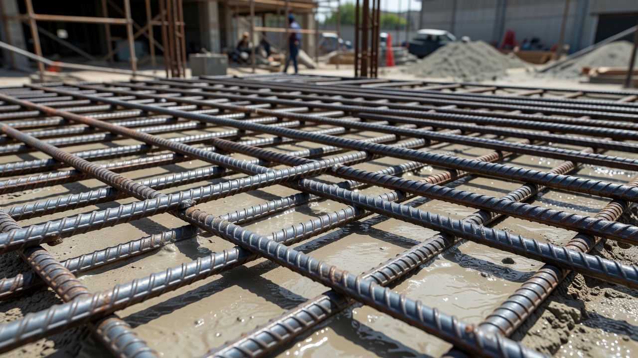
Rebar — a contraction of reinforcing bar — is a steel bar or mesh of steel wires embedded in concrete to provide tensile, shear, and in some configurations compressive strength to the composite material known as reinforced concrete. The fundamental engineering principle behind rebar use is straightforward: concrete possesses high compressive strength, typically ranging from 20 to 60 MPa (3,000 to 8,500 psi) for normal-strength mixes and exceeding 100 MPa (14,500 psi) for high-performance formulations, yet its tensile strength is a fraction of this — roughly 2 to 5 MPa (300 to 700 psi), or approximately 8% to 12% of its compressive capacity. This profound asymmetry in mechanical behavior means unreinforced concrete is unsuitable for structural elements subjected to bending, tension, or shear — essentially all beams, slabs, columns subject to eccentric loading, footings, and retaining walls.
Structural steel, by contrast, provides tensile yield strengths ranging from 280 MPa (40,000 psi) for legacy Grade 40 bars to 690 MPa (100,000 psi) for Grade 100 bars, with an elastic modulus of approximately 200 GPa (29,000 ksi). The coefficient of thermal expansion for both concrete and steel is nearly identical — approximately 10 × 10⁻⁶ to 12 × 10⁻⁶ per °C (5.5 × 10⁻⁶ to 6.5 × 10⁻⁶ per °F) — minimizing thermal stress at the interface under temperature variations. This thermal compatibility, combined with the mechanical interlock provided by surface deformations (ribs or lugs) rolled onto the bar during manufacture, ensures the two materials act compositely: the concrete carries compression, the steel carries tension, and the bond between them transfers stresses across the interface.
The invention of reinforced concrete is credited to French gardener Joseph Monier, who received a patent in 1867 for reinforcing flowerpots with iron wire mesh. Monier extended his patent to beams and slabs, and by the 1880s the German firm Wayss & Freytag had systematized the technology, publishing design methods in 1887. The first reinforced concrete bridge — the Alvord Lake Bridge in San Francisco’s Golden Gate Park — was built by Ernest L. Ransome in 1889 and remains in service, demonstrating the durability of properly designed reinforced concrete. Ransome also invented the twisted square rebar, a precursor to modern deformed bars, recognizing early that smooth bars could slip within the concrete matrix and fail the composite action.
Modern rebar is produced through hot-rolling of steel billets, during which the surface deformations are impressed onto the bar. These deformations must conform to ASTM A615 or equivalent standards specifying minimum rib height, spacing, and geometry to ensure adequate bond strength. The bond between rebar and concrete develops through three mechanisms: chemical adhesion between the steel surface and cement paste, friction due to the normal pressure of concrete shrinkage, and — most significantly — mechanical bearing of the deformations against the surrounding concrete. When a reinforced concrete beam is loaded in bending, the tension in the rebar is transferred to the concrete through bond stress at the steel-concrete interface. Without deformations, the bond would rely solely on chemical adhesion and friction, both of which degrade with time and loading cycles, leading to excessive slip and loss of composite action.
The selection of rebar type depends on exposure conditions, design life requirements, initial cost, life-cycle cost analysis, and constructability. The following types represent the principal options available in modern construction practice.
Carbon steel rebar, commonly called “black bar” due to the dark mill scale on its surface, is the most widely used reinforcing steel worldwide. Produced per ASTM A615, it is available in Grades 40, 60, 75, 80, and 100, with Grade 60 (420 MPa yield) accounting for the vast majority of building and bridge construction. Its chemical composition typically limits carbon to 0.30–0.50%, manganese to 0.60–1.50%, phosphorus to 0.050% maximum, and sulfur to 0.060% maximum. Carbon steel rebar provides high strength at low cost — approximately $0.50–$1.00 per pound for Grade 60 — making it the economic default where corrosion exposure is not a concern, such as interior building elements, arid climates, and concrete with adequate cover and low permeability.
The principal disadvantage of carbon steel rebar is its susceptibility to corrosion when the passive alkaline environment of concrete is compromised. Once corrosion initiates, the rust products (Fe₂O₃·H₂O and related iron oxides) occupy 3 to 6 times the volume of the original steel, generating expansive stresses that crack the concrete cover, accelerate further moisture and chloride ingress, and ultimately lead to spalling and loss of bond. In severe environments — coastal structures, bridge decks in regions using deicing salts, wastewater treatment facilities — unprotected carbon steel rebar can begin corroding within 10 to 15 years of service, compared to design lives of 75 to 100 years for major infrastructure.
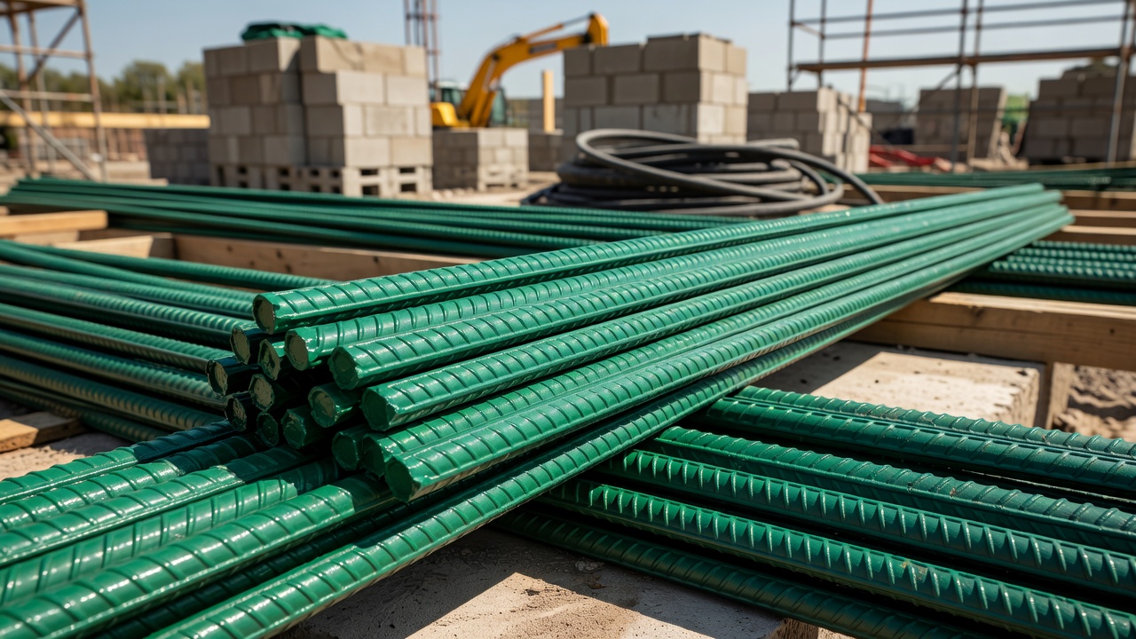
Epoxy-coated rebar (ECR) consists of carbon steel rebar coated with a fusion-bonded epoxy powder applied by electrostatic spray and cured in an oven. The epoxy coating, typically 175 to 300 μm (7 to 12 mils) thick per ASTM A775, acts as a physical barrier isolating the steel from moisture, oxygen, and chlorides. ECR became widely adopted in the United States during the 1970s and 1980s for bridge decks, with the FHWA actively promoting its use as a primary corrosion protection strategy. It remains the most common corrosion-resistant reinforcement in North American highway bridges, accounting for an estimated 70% of bridge deck rebar installations.
The effectiveness of ECR depends critically on coating integrity. Field handling, cutting, bending, and placement inevitably cause some coating damage — nicks, scrapes, and holidays — that create small anodic sites on the exposed steel. In chloride-contaminated concrete, these small anodes combined with large cathodic areas of intact coating can accelerate localized (pitting) corrosion at the damage sites, a phenomenon known as “undercutting corrosion.” ASTM A775 limits allowable coating damage to 2% of the surface area in any 300 mm (12 in) length of bar, and damaged areas must be repaired with compatible epoxy patching compound before concrete placement. The long-term performance of ECR has been debated: studies by the Florida Department of Transportation and others have shown that ECR bridge decks can exhibit significant coating disbondment and under-film corrosion after 20–30 years, though the corrosion rate is generally slower than bare steel. Current practice combines ECR with supplementary protection — low-permeability concrete, increased cover, and corrosion-inhibiting admixtures — for critical structures.
Galvanized rebar is carbon steel rebar hot-dip galvanized with a zinc coating per ASTM A767. The zinc provides both a barrier and sacrificial (galvanic) protection mechanism: zinc corrodes preferentially to steel, and even if the coating is scratched or damaged, the surrounding zinc continues to protect the exposed steel cathodically. The zinc coating thickness is specified by mass — typically 610 g/m² (2.0 oz/ft²) for bars 15.9 mm (No. 5) and larger, and 550 g/m² (1.8 oz/ft²) for smaller bars — corresponding to approximately 85–100 μm (3.5–4 mils) of zinc.
Galvanized rebar has several advantages over epoxy-coated rebar: better handling tolerance (the zinc-iron intermetallic layers are metallurgically bonded to the steel and resist chipping), superior field repair characteristics (zinc-rich paint can be applied to damaged areas), and the sacrificial protection of zinc at coating breaks. However, zinc corrodes at a higher rate in highly alkaline environments (pH > 13) and is attacked by the alkaline concrete pore solution during curing, consuming some of the coating. The corrosion products of zinc (zinc oxide and zinc hydroxide) are less voluminous than iron rust, reducing the risk of cracking, and the reaction between zinc and fresh concrete evolves hydrogen gas, which can be mitigated by chromate passivation treatment — though hexavalent chromium restrictions have led to development of chromium-free passivation alternatives. Galvanized rebar is widely used in Europe, Australia, and the Middle East, with growing acceptance in North American transportation structures.
Stainless steel rebar, manufactured per ASTM A955, provides the highest level of corrosion resistance among metallic reinforcement options. Stainless steels contain a minimum of 10.5% chromium, which forms a stable, self-healing passive chromium oxide film on the surface. Common grades for reinforcement include:
| Grade (UNS) | Nominal Composition | PRE Number | Relative Corrosion Resistance |
|---|---|---|---|
| 304 (S30400) | 18% Cr, 8% Ni | 18 | Good — suitable for moderate chloride exposure |
| 316 (S31600) | 16% Cr, 10% Ni, 2% Mo | 24 | Very good — marine and deicing salt exposure |
| Duplex 2205 (S32205) | 22% Cr, 5% Ni, 3% Mo, 0.15% N | 34 | Excellent — highly aggressive environments |
| XM-28 (S24100) | 17% Mn, 6% Ni, 2% Cr | — | High strength, low-nickel alternative |
The Pitting Resistance Equivalent (PRE) number, calculated as PRE = %Cr + 3.3(%Mo) + 16(%N), indicates relative resistance to pitting corrosion. Duplex 2205 with a PRE of 34 provides exceptional chloride resistance and yield strengths of 500–550 MPa (72–80 ksi), substantially higher than 304 or 316 grades.
Stainless steel rebar costs 4 to 8 times that of carbon steel, and 2 to 4 times that of epoxy-coated rebar. For this reason, its use is typically reserved for the most aggressive environments or where life-cycle cost analysis demonstrates a return on investment: coastal bridge substructures in the tidal and splash zones, seawalls, chemical processing facilities, and structures with 100+ year design lives where maintenance access is impossible or extremely costly. The Oregon Department of Transportation’s Haynes Inlet Bridge (2004) used 316LN stainless rebar in the substructure as part of a high-performance concrete strategy for a 120-year service life. The New York State Thruway Authority has used duplex 2205 rebar for critical bridge decks, citing projected maintenance savings that offset the premium over a 75-year life cycle.
Glass Fiber Reinforced Polymer (GFRP) rebar is a non-metallic alternative consisting of continuous glass fibers embedded in a polymer resin matrix (typically vinyl ester or epoxy), providing a reinforcement that is completely immune to electrochemical corrosion. GFRP bars have tensile strengths of 600–1,000 MPa (87–145 ksi) in the longitudinal direction, but a much lower elastic modulus than steel — 40–60 GPa (6,000–8,700 ksi) compared to 200 GPa for steel — meaning GFRP-reinforced members exhibit larger deflections and wider cracks under service loads than equivalent steel-reinforced members.
GFRP rebar is manufactured per ACI 440.1R-15 and ACI 440.6-08, with ASTM D7957 for solid round bars. Its advantages include: complete corrosion immunity, electromagnetic neutrality (essential for MRI facilities, compass calibration pads, and rail transit signal infrastructure), high strength-to-weight ratio (approximately one-quarter the weight of steel), and excellent fatigue resistance. Limitations include: brittle failure behavior (no yield plateau — rupture occurs at ultimate strain without warning), low transverse and shear strength, sensitivity to alkaline environments at elevated temperatures (resin degradation), lower fire resistance than steel, and the inability to be field-bent. GFRP bars must be bent to shape at the factory during manufacture, before the resin cures. They are used in bridge decks, barrier walls, seawalls, chemical plant structures, and MRI suites — anywhere corrosion or electromagnetic interference is the primary design constraint.
Steel rebar is designated by a bar number that corresponds approximately to the nominal diameter in eighths of an inch. This naming convention, established by the American Society for Testing and Materials (ASTM), is universally used in North American construction documentation.
| Bar Size | Nominal Diameter (in) | Nominal Diameter (mm) | Nominal Area (in²) | Nominal Area (mm²) | Weight (lb/ft) | Weight (kg/m) |
|---|---|---|---|---|---|---|
| #3 | 0.375 (3/8") | 9.53 | 0.11 | 71 | 0.376 | 0.561 |
| #4 | 0.500 (1/2") | 12.7 | 0.20 | 129 | 0.668 | 0.996 |
| #5 | 0.625 (5/8") | 15.88 | 0.31 | 200 | 1.043 | 1.556 |
| #6 | 0.750 (3/4") | 19.05 | 0.44 | 284 | 1.502 | 2.24 |
| #7 | 0.875 (7/8") | 22.23 | 0.60 | 387 | 2.044 | 3.049 |
| #8 | 1.000 (1") | 25.4 | 0.79 | 509 | 2.67 | 3.982 |
| #9 | 1.128 | 28.65 | 1.00 | 645 | 3.40 | 5.071 |
| #10 | 1.270 | 32.26 | 1.27 | 819 | 4.303 | 6.418 |
| #11 | 1.410 | 35.81 | 1.56 | 1,006 | 5.313 | 7.924 |
| #14 | 1.693 | 43.0 | 2.25 | 1,452 | 7.65 | 11.41 |
| #18 | 2.257 | 57.33 | 4.00 | 2,581 | 13.6 | 20.28 |
Metric bar designations indicate the nominal diameter in millimetres: a 10M bar has a nominal diameter of 11.3 mm (actual), 15M = 16.0 mm, 20M = 19.5 mm, 25M = 25.2 mm, 30M = 29.9 mm, 35M = 35.7 mm, 45M = 43.7 mm, and 55M = 56.4 mm. Metric bars are manufactured to CSA G30.18 in Canada and to national equivalents of EN 10080 in Europe, BS 4449 in the UK, and JIS G 3112 in Japan.
| Grade (ASTM A615) | Metric Equivalent | Minimum Yield Strength | Minimum Tensile Strength | Elongation (200 mm) |
|---|---|---|---|---|
| Grade 40 | 280 MPa | 40,000 psi (280 MPa) | 60,000 psi (420 MPa) | ≥ 12% (#3–#6), ≥ 9% (#7–#11) |
| Grade 60 | 420 MPa | 60,000 psi (420 MPa) | 90,000 psi (620 MPa) | ≥ 9% (#3–#6), ≥ 7% (#7–#11) |
| Grade 75 | 520 MPa | 75,000 psi (520 MPa) | 100,000 psi (690 MPa) | ≥ 7% (#3–#11) |
| Grade 80 | 550 MPa | 80,000 psi (550 MPa) | 105,000 psi (725 MPa) | ≥ 7% (#3–#11) |
| Grade 100 | 690 MPa | 100,000 psi (690 MPa) | 115,000 psi (790 MPa) | ≥ 7% (#3–#11) |
Grade 60 dominates all categories of construction — buildings, bridges, pavements, and retaining structures. ASTM A706 covers low-alloy steel rebar specifically formulated for weldability. A706 bars have lower carbon content (0.30% maximum) and carbon equivalent (0.55% maximum), along with tighter controls on phosphorus and sulfur. A706 is required in seismic-force-resisting systems where rebar may be welded to structural steel elements, and is preferred where ductility is critical. A706 can be specified as Grade 60 or Grade 80.
Every bar shipped in the United States carries a rolled-in marking pattern that identifies:
A bar marked “[Mill] 6 S —” is a #6, Grade 60, carbon steel bar from the identified mill. This traceability is essential for quality assurance during construction and for forensic investigation after failures.
Concrete cover — the thickness of concrete between the outer surface of the embedded rebar and the nearest concrete surface — is the primary defense against rebar corrosion and fire damage. Cover serves three essential functions: providing the alkaline environment that passivates the steel, creating a physical barrier to the ingress of chlorides, moisture, and carbon dioxide, and providing thermal protection to prevent rebar from reaching critical temperatures during fire exposure.
The American Concrete Institute’s Building Code (ACI 318-19) Table 20.6.1.3.1 prescribes minimum concrete cover for cast-in-place non-prestressed reinforcement:
| Concrete Element | Bar Size | Minimum Cover |
|---|---|---|
| Concrete cast against and permanently exposed to earth | All sizes | 75 mm (3 in) |
| Concrete exposed to earth or weather: | No. 6 through No. 18 | 50 mm (2 in) |
| No. 5 and smaller | 40 mm (1.5 in) | |
| Concrete not exposed to weather or in contact with ground: | ||
| Slabs, walls, joists — No. 11 and smaller | 20 mm (3/4 in) | |
| Slabs, walls, joists — No. 14 and 18 | 40 mm (1.5 in) | |
| Beams, columns, pedestals — primary reinforcement | All sizes | 40 mm (1.5 in) |
| Shells and folded plate members — No. 6 and larger | 20 mm (3/4 in) |
For precast concrete manufactured under controlled conditions, cover requirements can be reduced. For concrete exposed to deicing chemicals, brackish water, seawater, or spray — the code requires additional cover or alternative protective measures as determined by the licensed design professional.
The AASHTO LRFD Bridge Design Specifications impose stricter cover requirements reflecting the higher consequence of failure and aggressive exposure conditions of transportation infrastructure:
| Exposure Condition | Cover for Deck Surfaces (Top Mat) | Cover for Other Surfaces |
|---|---|---|
| Uncoated rebar, moderate exposure | 50 mm (2 in) | 50 mm (2 in) |
| Epoxy-coated rebar, moderate exposure | 50 mm (2 in) | 38 mm (1.5 in) |
| Uncoated rebar, severe exposure (deicing salts) | 65 mm (2.5 in) | 65 mm (2.5 in) |
| Epoxy-coated rebar, severe exposure | 65 mm (2.5 in) | 50 mm (2 in) |
| Cast-in-place piles, all exposures | — | 75 mm (3 in) |
For prestressed concrete bridge elements, AASHTO requires minimum 38 mm (1.5 in) cover for pretensioned strands in the top of decks and 32 mm (1.25 in) for strands elsewhere, with increases for severe exposure.
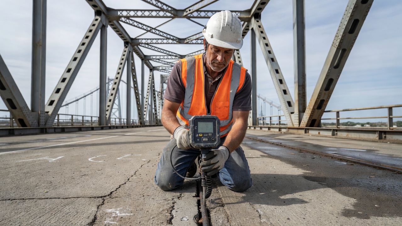
During construction and periodic inspection, cover depth is measured using a cover meter (also called a pachometer or rebar locator). These instruments operate on the principle of electromagnetic pulse induction or magnetic reluctance: a search coil generates a low-frequency magnetic field that induces eddy currents in the embedded rebar, and the resulting secondary magnetic field is detected and processed to determine bar location and cover depth. Modern cover meters achieve accuracies of ±1 to 3 mm and can detect bars to depths of 150–200 mm, depending on bar size and instrument type. Ground penetrating radar (GPR) at higher frequencies (1.5–2.6 GHz) can also map rebar layout and estimate cover over large areas, though with somewhat lower depth accuracy than dedicated cover meters.
Rebar corrosion is an electrochemical process analogous to a battery: it requires an anode (where iron dissolves), a cathode (where oxygen is reduced), an electrolyte (the concrete pore water containing dissolved ions), and a metallic path (the rebar itself) for electron flow. In healthy concrete, the high alkalinity of the pore solution — pH 12.5 to 13.5, maintained by dissolved calcium, sodium, and potassium hydroxides from cement hydration — causes the formation of a dense, adherent, microscopic layer of gamma ferric oxide (γ-Fe₂O₃) on the steel surface. This passive film, typically 2 to 10 nanometers thick, reduces the corrosion rate to negligible levels (less than 0.1 μm per year).
The most common and aggressive depassivation mechanism is chloride ion ingress. Chlorides penetrate concrete through diffusion (concentration gradient), capillary absorption (wetting and drying cycles), and hydrostatic pressure (submerged elements). Common sources include deicing salts (sodium chloride, calcium chloride, magnesium chloride), seawater and sea spray, brackish groundwater, and chloride-containing aggregates or mix water (now prohibited in most jurisdictions).
Once chloride concentration at the rebar depth exceeds the chloride threshold — typically 0.05% to 0.10% water-soluble chloride by weight of cement (ACI 318 limits water-soluble chloride to 0.06% for reinforced concrete exposed to chlorides in service) — the passive film is locally destroyed. The anodic reaction proceeds:
Fe → Fe²⁺ + 2e⁻
The electrons flow through the rebar to cathodic sites, where oxygen reduction occurs:
O₂ + 2H₂O + 4e⁻ → 4OH⁻
The ferrous ions (Fe²⁺) react with hydroxide ions and oxygen to form various iron oxide and hydroxide corrosion products (rust):
4Fe(OH)₂ + O₂ → 2Fe₂O₃·H₂O + 2H₂O
The significance for structural inspection is that these rust products occupy 3 to 6 times the volume of the original metallic iron. The expansive pressure generated — which can exceed 30 MPa (4,350 psi) — far exceeds the tensile strength of concrete (2–5 MPa), causing radial cracking originating at the rebar-concrete interface. These cracks propagate outward to the concrete surface, typically appearing as linear cracks parallel to and directly above the rebar. Once the concrete cover has cracked, the path for chloride, moisture, and oxygen ingress is dramatically shortened, and the corrosion rate accelerates — a self-reinforcing cycle of deterioration.
Atmospheric carbon dioxide (CO₂), typically at 0.04% concentration (400 ppm), diffuses into concrete and reacts with calcium hydroxide [Ca(OH)₂] and other alkaline hydration products, forming calcium carbonate (CaCO₃):
Ca(OH)₂ + CO₂ → CaCO₃ + H₂O
This reaction consumes the alkaline reserve and lowers the pore water pH from 12.5–13.5 to approximately 8.5–9.0. Below pH 9, the passive film is no longer thermodynamically stable, and the steel is depassivated even in the absence of chlorides. The carbonation front advances into concrete at a rate proportional to the square root of time, with a carbonation coefficient that depends on concrete quality (water-cement ratio, cement type, curing) and environmental conditions (relative humidity, CO₂ concentration). In low-quality concrete with a w/c ratio of 0.6–0.7, the carbonation front may reach 25–30 mm depth in 20–30 years; in high-quality concrete (w/c < 0.40), carbonation depths are typically less than 5–10 mm over the same period. Carbonation-induced corrosion is most prevalent in older buildings, parking garages (elevated CO₂ from vehicle exhaust), and industrial environments.
Corrosion in reinforced concrete can occur as microcell corrosion, where anodic and cathodic reactions occur on the same bar in close proximity, or as macrocell corrosion, where the anode and cathode are separated by significant distances — sometimes meters — connected by the rebar network. Macrocell corrosion is particularly aggressive when chloride-contaminated concrete (forming a large anode) is adjacent to chloride-free concrete (forming a large cathode). A classic example is a bridge deck where the top mat of rebar in deck concrete is chloride-contaminated (anode), while the bottom mat in drier, chloride-free concrete acts as a large cathode. The large cathode-to-anode area ratio concentrates the corrosion current at the anodic sites, producing deep, localized pitting. This phenomenon is why half-cell potential surveys, which measure the corrosion potential at discrete points, must be interpreted with an understanding of the overall corrosion cell geometry.
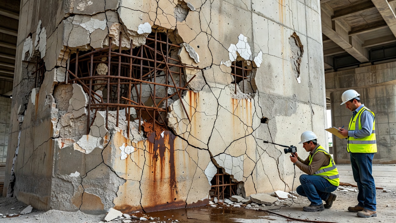
The detection of active or past rebar corrosion — and especially the identification of exposed rebar — is among the highest-priority tasks in concrete infrastructure inspection. Exposed rebar represents a critical finding under FHWA National Bridge Inspection Standards (NBIS), requiring immediate documentation, quantification of section loss, and structural evaluation.
Visual inspection remains the first line of assessment and identifies the visible manifestations of rebar corrosion: rust staining (brown-orange discoloration leaching from cracks or spalls onto the concrete surface), cracking parallel to the rebar (often the earliest visible sign of active corrosion, as rust expansion cracks the cover from within), spalling (loss of concrete sections exposing the underlying rebar), and delamination (subsurface separation of concrete layers, detectable by hollow sound when struck with a hammer or chain). Visual inspection is rapid and inexpensive but provides no information about rebar condition below the surface — the majority of rebar length in a structure is hidden from visual assessment.
The half-cell potential method measures the electrochemical potential of embedded rebar relative to a copper/copper-sulfate (Cu/CuSO₄) reference electrode placed on the concrete surface. The potential is measured at a grid of points (typically 300–600 mm spacing) and plotted as a potential map. Per ASTM C876, potentials more negative (lower) than -350 mV versus Cu/CuSO₄ indicate a greater than 90% probability of active corrosion; potentials between -200 and -350 mV indicate uncertain corrosion activity; potentials less negative (higher) than -200 mV indicate a greater than 90% probability of no active corrosion. Half-cell potential testing is the most widely used quantitative method for assessing rebar corrosion activity but has limitations: it indicates corrosion probability, not corrosion rate; it cannot quantify section loss; it requires electrical continuity of the rebar mat and a local electrical connection to the steel; and results are influenced by concrete moisture content, cover depth, and oxygen availability.
GPR systems for concrete inspection operate at center frequencies of 1.0 to 2.6 GHz, emitting electromagnetic pulses that reflect from interfaces with differing dielectric properties — including the concrete-rebar interface, the concrete-air interface at delaminations, and the concrete-steel interface at corrosion product layers. GPR can map rebar layout, estimate cover depth, detect delaminated areas (which appear as strong reflections due to the air gap), and when processed with amplitude analysis software, can identify areas of advanced corrosion where the rebar reflection amplitude is attenuated by the presence of moisture and corrosion products. GPR mounted on vehicles or drones can survey entire bridge decks at speeds up to 80 km/h (50 mph), producing continuous condition maps at much higher productivity than manual methods.
Chloride ion concentration in concrete is measured from drilled powder samples at incremental depths, typically by acid-soluble (total chloride) or water-soluble (free chloride) extraction followed by titration per AASHTO T 260. Chloride profiles — concentration versus depth curves — are plotted to determine the chloride concentration at rebar depth and to estimate the diffusion coefficient and time-to-corrosion initiation for remaining service-life prediction. Concentrations exceeding 0.05% to 0.10% water-soluble chloride by weight of cement at the rebar depth indicate active or impending corrosion.
Modern AI-driven inspection platforms, such as TarmacView, integrate high-resolution visual imagery (captured by drones, ground robots, or handheld cameras) with computer vision algorithms trained to detect and classify exposed rebar, rust staining, spalling, delamination, and associated crack patterns. These systems process thousands of images across large structures — entire bridge decks, parking structures, airport pavements — and identify defect locations, quantify defect dimensions (area of exposed rebar, length of cracks), assign severity ratings, and generate inspection reports with georeferenced defect maps. TarmacView specifically detects exposed_rebar as a critical defect classification within its structural defect detection pipeline, enabling rapid prioritization of areas requiring immediate repair versus those that can be monitored over time. The combination of AI-based defect detection with supplementary NDE data (GPR, half-cell potential, chloride profiles) provides a comprehensive condition assessment that guides maintenance and capital planning decisions.
The National Bridge Inspection Standards (NBIS), codified at 23 CFR Part 650 Subpart C, establish the framework for bridge inspection in the United States. Under NBIS, reinforced concrete bridge elements are evaluated using two complementary systems.
The NBI uses a 0–9 scale for rating the condition of the deck, superstructure, and substructure:
| Rating | Condition | Description |
|---|---|---|
| 9 | Excellent | New condition, no noteworthy deficiencies |
| 8 | Very Good | No problems noted |
| 7 | Good | Some minor problems, typically superficial |
| 6 | Satisfactory | Minor section loss, cracking, spalling, or scour |
| 5 | Fair | Minor section loss of primary members; advanced section loss of secondary members; may have minor spalling |
| 4 | Poor | Advanced section loss or deterioration of primary structural elements |
| 3 | Serious | Section loss seriously affects primary structural components; fatigue cracks in steel or shear cracks in concrete |
| 2 | Critical | Advanced deterioration; may require closing the bridge until corrective action is completed |
| 1 | Imminent Failure | Major deterioration or section loss; closure necessary |
| 0 | Failed | Out of service, beyond corrective action |
For reinforced concrete elements, exposed rebar with measurable section loss typically corresponds to condition ratings of 5 (Fair) to 4 (Poor). Exposed rebar with significant section loss (greater than 10% of original cross-sectional area) or active corrosion accompanied by delamination and spalling affecting primary load-carrying members triggers ratings of 4 (Poor) or 3 (Serious).
Element-level inspection, per the AASHTO Manual for Bridge Element Inspection, quantifies deterioration in four condition states for each defined element:
For reinforced concrete elements, Defect 1080 (Delamination/Spall/Patched Area) and Defect 1090 (Exposed Rebar) are the primary corrosion-related defects. Each condition state quantifies the percentage of element area affected: for Defect 1090, Condition State 2 typically corresponds to less than 2% of the element area with exposed rebar and no section loss; Condition State 3 corresponds to 2–10% or any exposed rebar with measurable section loss; and Condition State 4 corresponds to more than 10% of element area or exposed rebar with significant section loss requiring structural evaluation.
The FHWA defines a critical finding as a structural or safety-related deficiency that requires immediate follow-up inspection or action. For reinforced concrete, critical findings include: exposed rebar with measurable section loss in primary load-carrying members; spalling or delamination that could fall onto traffic; severe cracking indicating imminent structural distress; and any condition that, in the inspector’s judgment, threatens public safety. Critical findings must be reported to the bridge owner within 24 hours, and follow-up actions — which may range from emergency load posting to immediate closure — must be initiated promptly.
Airport pavements and structures present unique demands on reinforced concrete due to heavy and repetitive aircraft loading, exposure to deicing and anti-icing chemicals, jet fuel and hydraulic fluid spillage, and the operational imperative to minimize pavement downtime for maintenance.
The Federal Aviation Administration Advisory Circular AC 150/5320-6G (Airport Pavement Design and Evaluation) provides the standards for rigid pavement design at U.S. civil airports. FAA rigid pavements are constructed as either jointed plain concrete pavement (JPCP) or jointed reinforced concrete pavement (JRCP), with continuous reinforced concrete pavement (CRCP) used in some applications.
In JPCP — the most common airport pavement type — transverse joints are spaced at 4.5 to 7.6 m (15 to 25 ft) and the concrete is unreinforced except for dowel bars (smooth round bars, typically 32–38 mm or 1.25–1.5 in diameter, 460–510 mm or 18–20 in long) at transverse joints to transfer load between adjacent slabs, and tie bars (deformed bars, typically 16 mm or #5, 760 mm or 30 in long) at longitudinal joints to prevent lane separation. The steel in JPCP is at the joints only, not distributed throughout the slab.
In JRCP, distributed reinforcement — typically 0.10% to 0.25% of the cross-sectional area — is provided in addition to joint dowels. This reinforcement holds tight cracks that form between joints but does not prevent cracking.
CRCP, which has no transverse joints, relies on a higher steel ratio — typically 0.6% to 0.8% longitudinally — to distribute shrinkage and thermal cracks into a closely spaced (0.6–1.8 m) pattern of fine, tight cracks. CRCP is used on some U.S. interstate highways and has been applied to airport aprons and taxiways where long-term joint maintenance is undesirable.
Aircraft deicing fluids — primarily propylene glycol and ethylene glycol — are not themselves corrosive to rebar, but runway and taxiway deicing chemicals, including potassium acetate, sodium acetate, sodium formate, and urea, present corrosion concerns. Potassium acetate and sodium acetate deicers have been shown to accelerate the alkali-silica reaction (ASR) in susceptible aggregates and can increase concrete permeability, indirectly accelerating chloride ingress. More critically, many airports also use chloride-based deicers (sodium chloride, calcium chloride) on roadways, parking areas, and sometimes on airfield pavements during extreme cold events. The combination of heavy aircraft loads, joint movements, and chemical exposure creates an aggressive environment for embedded rebar.
Airport terminal buildings, parking structures, maintenance hangars, and air traffic control towers are substantial reinforced concrete structures. Terminal buildings typically use cast-in-place reinforced concrete frames with long-span beam systems and post-tensioned slabs. Parking structures at airports are among the most corrosion-aggressive environments for rebar, combining exposure to road salts from vehicles, carbonation from vehicle exhaust, and repeated wetting-drying cycles. Hangar floors, exposed to jet fuel, hydraulic fluids, and heavy point loads from aircraft jacks and maintenance stands, require high-quality concrete with low permeability and, often, epoxy-coated or corrosion-inhibited rebar.
When exposed or corroded rebar is identified during inspection, the selection of repair strategy depends on the extent and severity of deterioration, the cause of corrosion, the remaining service-life requirements, and economic analysis.
For localized spalls and delaminations where corrosion is the cause, the standard repair sequence includes: saw-cutting the perimeter of the repair area to sound concrete at least 25 mm (1 in) deep, removing all delaminated and chloride-contaminated concrete (typically to a minimum of 25 mm behind the rebar on all sides), abrasive blast-cleaning the exposed rebar to a near-white metal condition (SSPC-SP 10 / NACE No. 2), coating the cleaned rebar with a bonding agent or corrosion-inhibiting primer, and placing a low-shrinkage, low-permeability repair mortar or concrete. If the rebar section loss exceeds 10% of the original cross-sectional area, supplemental reinforcement or bar splicing may be required per structural engineering evaluation. Patching alone does not address the root cause of corrosion; without supplementary protection, the repair perimeter becomes a new corrosion cell boundary where chloride-contaminated concrete (anode) contacts the clean patch (cathode), potentially accelerating corrosion in the surrounding unrepaired concrete — a phenomenon known as the “ring anode effect” or “incipient anode effect.”
Cathodic protection (CP) is the only rehabilitation technique that has been proven to stop rebar corrosion in chloride-contaminated concrete regardless of chloride content. Two systems are in common use:
Galvanic (Sacrificial) Cathodic Protection uses zinc anodes — either zinc mesh embedded in a concrete overlay, or discrete zinc anode units embedded in patch repairs at regular spacing — that corrode sacrificially to protect the rebar. These systems are self-regulating (require no external power), have a design life of 15–25 years depending on anode mass and current demand, and are well-suited to bridge decks, parking structures, and marine substructures where overlay placement is feasible.
Impressed Current Cathodic Protection (ICCP) uses an external DC power supply and inert anodes — typically mixed metal oxide (MMO) coated titanium mesh, ribbon, or discrete anodes embedded in a cementitious or polymer concrete overlay — to drive a protective current onto the rebar. Current densities are typically 2–20 mA/m² of steel surface. ICCP systems require continuous power (approximately $0.50–$2.00 per square meter per year in electricity costs), periodic monitoring and adjustment, and maintenance of the power supply and wiring, but can provide protection for 30–50+ years when properly maintained. ICCP is the preferred solution for large structures — bridge substructures, marine terminals, large parking garages — where long-term protection is essential and galvanic systems would require impractically large anode masses.
Electrochemical chloride extraction is a temporary treatment (4–8 weeks) in which a high-current DC field is applied between an external anode (typically steel or titanium mesh embedded in a temporary electrolyte medium) and the rebar (cathode). The applied field drives chloride ions out of the concrete toward the external anode, where they are captured in the electrolyte. ECE can remove 40–90% of chlorides from the concrete cover zone, potentially restoring passivity. Re-alkalization uses a similar electrochemical process to restore the alkalinity of carbonated concrete by introducing an alkaline electrolyte (sodium or potassium carbonate solution) that penetrates under the applied field. Both are specialized treatments requiring experienced contractors and are most applicable where the concrete matrix is otherwise sound and only the cover zone is contaminated.
Corrosion inhibitors — both admixtures added to fresh concrete (calcium nitrite, amino alcohols) and surface-applied migrating corrosion inhibitors (MCI) — are used to reduce corrosion rates. Calcium nitrite [Ca(NO₂)₂], the most extensively researched corrosion-inhibiting admixture, works by oxidizing ferrous ions at the steel surface to form a stable passive film. It is added at dosages of 10–30 L/m³, with the required dosage proportional to the anticipated chloride exposure. Surface-applied MCIs are applied to existing concrete and penetrate by capillary action and vapor diffusion to form a protective molecular layer on the rebar surface. Their effectiveness in heavily chloride-contaminated concrete remains debated, but they are used as a low-cost supplementary measure where more aggressive treatments are not feasible.
For columns and piers where corrosion has caused significant section loss, and where replacement is impractical, external confinement with FRP (Fiber Reinforced Polymer) wraps or steel jackets provides structural strengthening. The damaged concrete is first patched and the rebar cleaned or supplemented; then continuous layers of carbon or glass FRP fabric saturated with epoxy resin are wrapped around the column, providing confinement that increases compressive strength and ductility. FRP systems are lightweight, corrosion-proof, and can be installed with minimal disruption. For larger section losses, reinforced concrete or shotcrete jackets may be applied.
When rebar section loss exceeds 20–25% in primary load-carrying members, when corrosion has progressed to the point where the remaining bond between rebar and concrete is severely compromised over large areas, or when the cost of multiple repairs over the remaining service life exceeds replacement cost, full-depth replacement of the element is the appropriate strategy. In bridge decks, this typically means hydro-demolition to remove the chloride-contaminated concrete while preserving sound concrete below, followed by replacement of the top reinforcement mat and placement of a new concrete overlay. For substructures and foundations, replacement may involve constructing new elements adjacent to or around the deteriorated elements — a costly and logistically complex undertaking that underscores the importance of proactive inspection and corrosion management.
The integration of AI-based inspection, such as TarmacView’s automated exposed rebar detection, with quantitative NDE methods now enables infrastructure owners to identify corrosion at its earliest visible stages, prioritize repairs based on objective condition data, and implement life-cycle cost-optimized maintenance strategies that extend the service life of reinforced concrete assets and protect public safety.
TarmacView AI-powered infrastructure inspection automatically identifies exposed rebar, rust staining, spalling, and delamination — enabling proactive maintenance and extending asset life.
Exposed rebar is a critical structural defect where reinforcing steel becomes visible at the concrete surface due to spalling, delamination, or insufficient cov...
Fiber-Reinforced Polymer (FRP) reinforcement consists of high-strength fibers (glass, carbon, basalt, aramid) embedded in a polymer matrix, used as non-corrosiv...
Tie bars are deformed steel bars placed across longitudinal joints in concrete pavement to prevent lane separation and hold adjacent slabs tightly together. Unl...