Impact-Echo Testing
Impact-Echo is a stress-wave nondestructive testing method where a short-duration mechanical impact on a concrete surface generates stress waves that reflect fr...
32 min read
Non-Destructive Testing
Concrete NDT
+4
The Schmidt rebound hammer is a spring-driven device that impacts concrete surfaces and measures rebound distance, providing a quick approximate indication of surface hardness and uniformity correlating roughly to compressive strength. Covers principle, operation, ASTM C805 procedure, calibration, correlation curves, limitations, and use as an NDT screening tool.

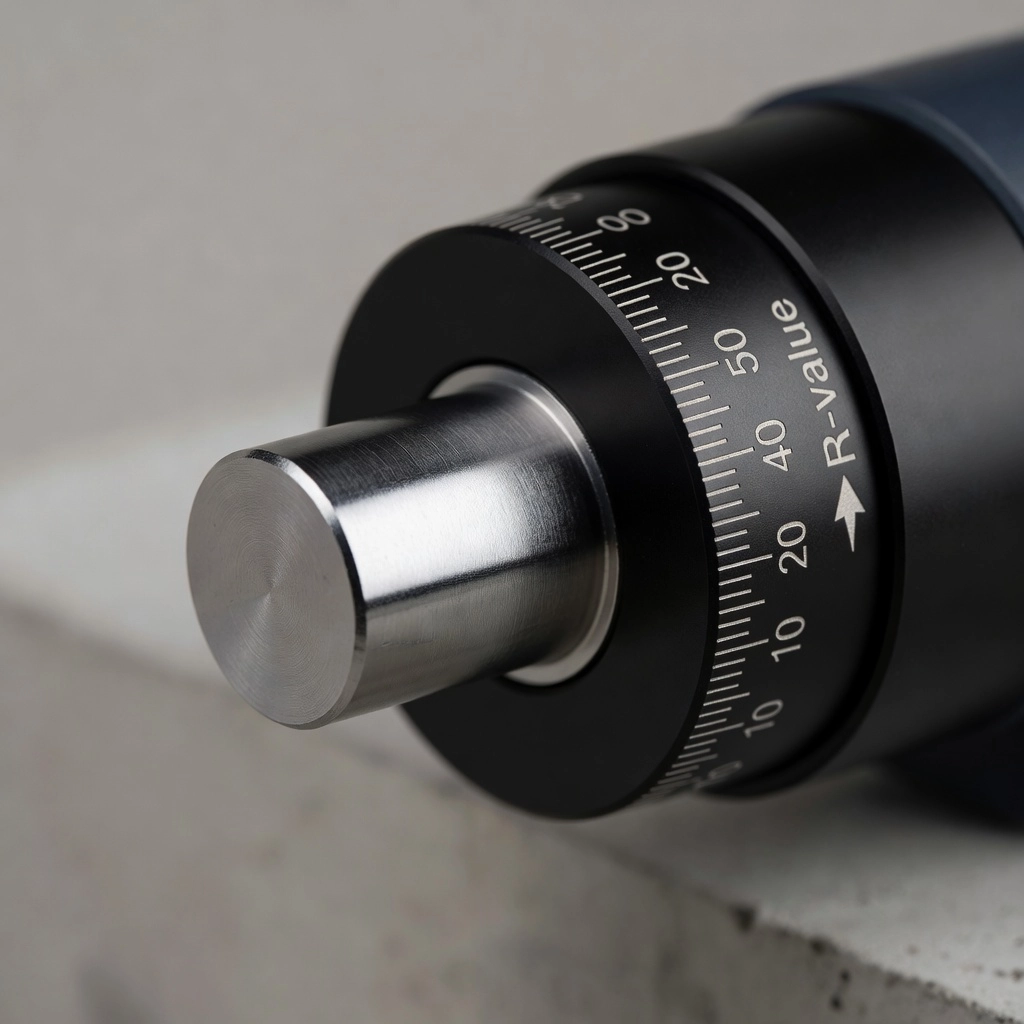
The Schmidt rebound hammer, also known as the concrete test hammer, Swiss hammer, or rebound hammer, is a portable non-destructive testing (NDT) instrument that measures the surface hardness of hardened concrete by quantifying the rebound distance of a spring-loaded mass after impact with the concrete surface. The rebound distance is expressed as a dimensionless rebound number (R-value) or Q-value in more advanced digital instruments, which serves as an index of surface hardness that can be correlated approximately to compressive strength.
The operating principle is grounded in fundamental physics: when a moving mass strikes a solid surface, the energy not absorbed by the surface through elastic and plastic deformation is returned to the mass as kinetic energy, causing it to rebound. The proportion of energy returned — and therefore the rebound distance — increases as the target surface becomes harder and more elastic. For concrete, the surface hardness measured by the rebound hammer depends on the stiffness and density of the cement paste matrix, the hardness of coarse aggregates near the surface, and the overall quality and consolidation of the concrete.
The device was invented in 1954 by Ernst Otto Schmidt, a Swiss civil engineer in Zurich, Switzerland, and was commercialized by Antonio Brandestini through Proceq SA (now part of Screening Eagle Technologies). The original patent described a spring-driven steel hammer that strikes a steel plunger in contact with the concrete surface, with the rebound distance mechanically indicated on a linear scale. Proceq remains the dominant global manufacturer, with numerous manufacturers producing variants including Controls, Gilson, Qualitest, Humboldt, and ELE International.
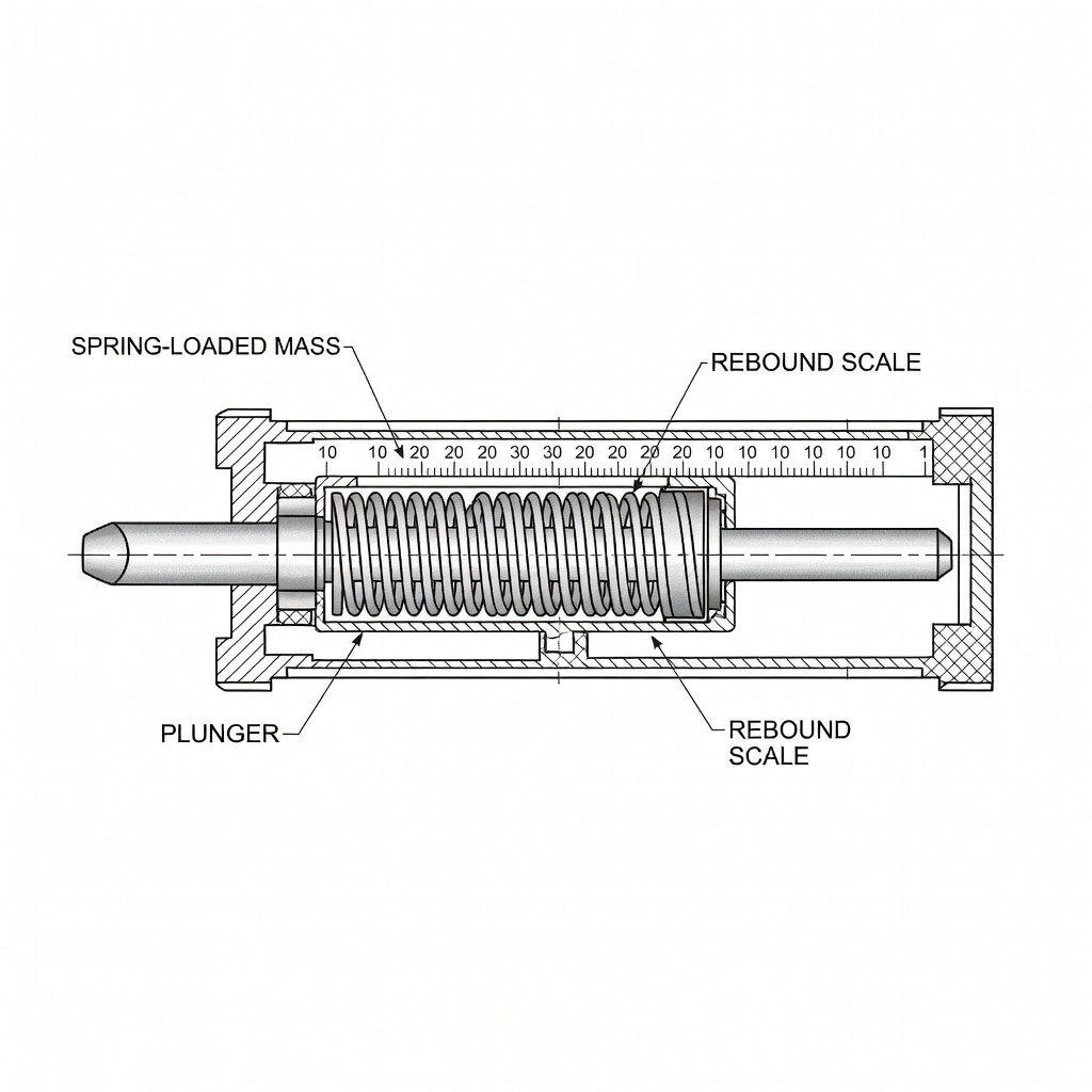
The rebound hammer operates by converting the kinetic energy of a known mass traveling at a known velocity into an impact force applied to the concrete through a hardened steel plunger. The internal spring mechanism is compressed by pushing the hammer body toward the concrete surface while the plunger remains stationary against the surface. At a predetermined compression point, the spring latch releases, propelling the mass forward toward the plunger. The mass strikes the plunger shoulder, and the portion of energy that is not dissipated through the concrete’s elastic and plastic deformation causes the mass to bounce backward. This rebound movement moves a sliding indicator along a graduated scale, where the position of the indicator is read as the rebound number.
The mathematical relationship governing the rebound is based on the conservation of energy. The initial potential energy stored in the compressed spring is defined as E = ½kx² where k is the spring constant and x is the compression distance. Upon release, this energy converts to kinetic energy of the mass: E = ½mv². At impact, part of this energy is transferred to the concrete, causing localized deformation and internal friction losses, while the remainder is returned to the mass as rebound energy. The rebound distance R is proportional to the square root of the ratio of returned energy to incident energy. For a Type N hammer with impact energy of 2.207 Nm (1.63 ft-lbf), the rebound number typically ranges from approximately 10 (very soft concrete) to 80 (very hard, high-strength concrete).
Rebound hammers are manufactured in several configurations distinguished by impact energy, measurement technology, and intended application. The two primary standard types defined in ASTM C805 are Type N and Type L.
The Type N hammer is the standard device for general-purpose concrete testing. It delivers an impact energy of 2.207 Nm (1.63 ft-lbf) and is designed for testing concrete members with thickness greater than 100 mm (4 inches) and compressive strengths in the range of 10 to 70 MPa (1,450 to 10,152 psi). The Type N hammer is suitable for structural elements including bridge girders, columns, beams, walls, slabs, pavements, and foundations. It is the most widely used configuration in North America, Europe, and Asia.
The Type L hammer delivers a reduced impact energy of 0.735 Nm (0.54 ft-lbf) — approximately one-third of the Type N energy. It is specifically designed for testing thin concrete sections less than 100 mm thick, green or early-age concrete where higher impact energy could cause surface damage, precast concrete elements such as pipes and panels, and low-strength concrete in the range of 5 to 30 MPa (725 to 4,350 psi). The lower impact energy provides more repeatable results on thin sections because it minimizes the influence of the backing support condition and reduces the risk of fracturing through thin elements. Type L hammers can be fitted with a mushroom plunger accessory that distributes the impact over a larger area, enabling testing on very low-strength or early-age concrete with compressive strengths as low as 5 MPa (725 psi).
| Model Type | Measurement Technology | Key Features | Strength Range |
|---|---|---|---|
| Original Schmidt (Analog) | Mechanical sliding scale | R-value display, no battery required, rugged mechanical construction | 10-70 MPa (Type N) |
| Original Schmidt Live (OS8000) | Electronic accelerometer | Digital R-value, GPS positioning, Bluetooth data transfer, cloud reporting | 10-70 MPa (Type N) |
| Silver Schmidt (PC/ST) | Optical encoder | Q-value measurement (friction-free), unaffected by impact angle, wider range | 10-100+ MPa |
| Silver Schmidt Live (OS8200) | Optical encoder | Q-value, Bluetooth, app-based data management, image and voice notes | 10-100+ MPa |
| Rock Schmidt (RS8000) | Electronic accelerometer | For rock and geological applications, higher impact energy | N/A |
The Silver Schmidt series represents the most advanced generation of rebound hammers. Instead of a mechanical sliding indicator, these instruments use an optical encoder to measure the rebound distance electronically. The Q-value produced by the optical encoder is independent of internal friction and impact angle, resulting in inherently higher repeatability compared to mechanical R-value measurements. The optical encoder approach also enables accurate testing on ultra-high performance concrete (UHPC) with compressive strengths up to 120 MPa (17,405 psi) when using operator-developed correlation curves.
Digital hammers incorporate onboard data logging, Bluetooth or Wi-Fi connectivity, and companion mobile applications that enable real-time data visualization, GPS tagged location mapping, integration of photographs and voice annotations, cloud-based report generation, and instant sharing with project stakeholders. The Paper Schmidt PS8000 is a specialized variant for testing paper rolls in industrial applications.
The internal mechanism of a rebound hammer comprises several precision-engineered components designed for consistent, repeatable energy delivery and measurement. The plunger is a hardened steel rod that contacts the concrete surface. It is spring-loaded to extend outward from the hammer body and transfers the impact force from the internal hammer mass to the concrete. The plunger face is typically flat with a hemispherical tip for Type N hammers, while mushroom-shaped plungers are available for Type L applications on soft concrete.
The hammer mass is a calibrated steel weight — typically approximately 250 grams for Type N hammers — that slides along a guide rod within the hammer body. The mass is connected to the main spring, which is the critical energy-storage component. The spring is pre-tensioned during the loading phase when the operator pushes the hammer body toward the plunger against the concrete surface. The spring characteristics (spring constant k approximately 0.8 to 1.2 N/mm for Type N, with free length and pre-compression calibrated to deliver exactly 2.207 Nm at release) are factory-calibrated and must be verified during periodic servicing.
The latch and release mechanism is a precision trigger that holds the spring in its fully compressed state until a critical compression point is reached, at which point the latch releases instantaneously. The release mechanism ensures that the hammer mass is always released at the same spring compression regardless of the operator’s pushing force, provided the operator pushes steadily past the release point. The release mechanism includes a capture latch that prevents the mass from striking the plunger more than once per test cycle.
The slide indicator in analog models consists of a metal rider that is carried forward by the rebounding hammer mass and remains at the peak rebound position, held by friction or a spring detent. The rider indicates the rebound distance on a graduated scale printed on the hammer body, typically graduated from 10 to 100 in increments of 1 rebound unit. Digital instruments replace the mechanical rider with an optical encoder that tracks the mass position using a slotted disk and photodetector, or an accelerometer that measures the deceleration and rebound acceleration profile of the mass.
The impact dynamics at the concrete surface involve a complex stress wave interaction. Upon impact, a compressive stress wave propagates into the concrete at approximately 3,500 to 4,500 m/s. The wave amplitude attenuates with depth and is partially reflected at interfaces between the cement paste and aggregate particles. The proportion of energy returned to the hammer mass depends on the mechanical impedance of the concrete surface layer, which is a function of the elastic modulus and density of the near-surface material. This is why the rebound hammer is sensitive primarily to the outermost 20 to 30 mm of concrete — approximately the depth influenced by the propagating stress wave during the impact duration of 0.5 to 2 milliseconds.
The rebound number is the dimensionless index produced by the rebound hammer test. In analog instruments, it is designated as the R-value and is read directly from the mechanical scale. In digital instruments using optical encoder technology, it is designated as the Q-value. Both terms refer to the rebound distance expressed as a percentage of the total possible rebound (where zero rebound would be 0 and full return to the compressed start position would be approximately 100).
The R-value scale typically ranges from 10 to 80 for practical concrete testing. Values below 10 indicate extremely soft or deteriorated concrete that may not be suitable for testing with a standard hammer. Values above 80 are uncommon in conventional concrete but are observed in UHPC and on the calibration test anvil (where the certified reading is 80 ± 2). The following table shows typical rebound numbers and their approximate relationship to concrete quality:
| Rebound Number (R) | Concrete Quality Indication | Approximate Strength Range (MPa) |
|---|---|---|
| > 40 | Excellent / Very Good | > 40 |
| 35 - 40 | Good | 30 - 40 |
| 30 - 35 | Fair | 20 - 30 |
| 25 - 30 | Poor | 10 - 20 |
| < 25 | Very Poor | < 10 |
Important caveat: These values are general indicators only. The actual relationship between rebound number and compressive strength is specific to each concrete mix and must be established through correlation testing following procedures in ACI 228.1R or EN 13791.
The Q-value measured by the Silver Schmidt series operates on the same physical principle but uses optical encoder measurement that eliminates the friction inherent in mechanical slide indicators. Q-values are typically numerically different from R-values for the same concrete because of the different measurement method. Correlation curves provided by the manufacturer convert Q-values to compressive strength estimates. The optical encoder approach also enables accurate measurements regardless of the impact angle, eliminating the need for angle correction factors that are required for mechanical R-value instruments.
The relationship between rebound number and concrete compressive strength is empirical rather than theoretical. There is no fundamental physical law that directly links surface hardness to compressive strength because the two properties are influenced by different material characteristics. Compressive strength depends primarily on the quality of the cement paste matrix and the paste-aggregate bond, while surface hardness depends more on the elastic properties of the near-surface layer and the stiffness of the aggregate particles near the impact point.
Despite this limitation, extensive research has shown that a useful correlation can be established for a specific concrete mixture by testing companion specimens. The process for developing a reliable correlation involves:
The resulting correlation equation is specific to that concrete mix, that hammer, and those test conditions. The ACI 228.1R procedure requires a minimum of 6 locations with 2 replicate cores each (12 cores total) taken from regions exhibiting a wide range of rebound numbers. The cores are tested for compressive strength per ASTM C42, and the results are used to develop the correlation.
EN 13791 requires a minimum of 9 cores from 9 different locations, with strict requirements for statistical analysis including calculation of the characteristic strength as the lower 5-percentile value. The European standard defines two approaches: an indirect method using rebound hammer testing combined with limited coring, and a direct method using cores exclusively.
Manufacturer-supplied conversion charts provided with rebound hammers are for general reference only. These charts are typically based on laboratory tests of a limited number of concrete mixes cured under standard conditions and do not account for the specific materials, mix proportions, moisture conditions, curing history, and age of the concrete being tested. ASTM C805 explicitly cautions that such manufacturer curves should not be used for acceptance or rejection of concrete without independent verification through site-specific correlation testing.
The following table shows the mathematical formulations used in the Silver Schmidt OS8200 reference curves for Type N hammers (cube specimens, 150 mm):
| Curve Name | Q Range | Equation (fck in N/mm²) | Form Factor |
|---|---|---|---|
| Lower 10% (old) | 22 - 75 | fck = 2.77e^0.048Q | 150 mm cube |
| Reference EU (old) | 21 - 62 | fck = 1.8943e^0.064Q | 150 mm cube |
| Reference CN | 20 - 75 | fck = 0.0244Q² − 0.6129Q + 10 | 150 mm cube |
| Reference RUS | 20 - 77 | fck = 0.03Q² − 0.86Q + 9.5 | 150 mm cube |
| Mean Strength | 10 - 75 | fck = 3.6473e^0.0475Q | 150 mm cube |
| Characteristic Strength | 10 - 95 | Step function (EN 13791) | 150 mm cube |
The characteristic strength curve from EN 13791 provides a conservative estimate with less than 5% probability of overestimating the true strength. This curve is a step function where specific Q-value ranges map to fixed strength values — for example, Q = 40-44 maps to 15 MPa, Q = 45-48 maps to 20 MPa, Q = 52-55 maps to 30 MPa, and Q = 75-80 maps to 95 MPa. This approach is designed for screening assessments where a margin of safety is required.
ASTM C805 — “Standard Test Method for Rebound Number of Hardened Concrete” — provides the standardized procedure for rebound hammer testing in North America. The European equivalent is EN 12504-2. The following summarizes the key procedural requirements.
The concrete member to be tested must be at least 100 mm (4 inches) thick and fixed within a structure. Thin sections or small specimens must be rigidly supported to prevent movement during impact, as any flexing or vibration of the member absorbs impact energy and produces falsely low rebound numbers. Test areas exhibiting honeycombing, scaling, surface voids, or high porosity must be avoided. The test surface must be clean, dry, and free from coatings, laitance, or loose mortar.
The test area must be at least 150 mm (6 inches) in diameter. Heavily textured surfaces or those with loose mortar must be ground flat using a medium-grain silicon carbide abrasive stone or a surface grinder. Smooth-formed surfaces or troweled finishes do not require grinding, but it is critical that results from ground and unground surfaces are not compared directly. Troweled surfaces typically exhibit higher rebound numbers than screeded or formed surfaces because of the denser surface layer created by finishing operations. When testing structural slabs, testing from the underside (formed surface) is preferred to avoid finished surface effects.
The concrete must not be frozen. Moist concrete at 0°C (32°F) or below can exhibit artificially high rebound values due to the increased stiffness of frozen pore water. The hammer itself is also affected by temperature — tests conducted with the hammer at -18°C (0°F) may produce readings reduced by as much as 2 to 3 rebound units. Testing should only be performed after the concrete has fully thawed.
The hammer is held firmly so that the plunger is perpendicular to the test surface. The operator gradually pushes the instrument toward the test surface with steady, even pressure until the hammer impacts. A smooth, consistent application of force is essential — jabbing or bumping the hammer produces unreliable readings. After impact, the operator maintains pressure on the instrument and depresses the side button to lock the plunger in the retracted position. The rebound number is read from the scale to the nearest whole number and recorded.
A total of ten readings are taken from each test area. The spacing between individual impact points must be at least 25 mm (1 inch), and the distance from any impact point to the edge of the member must be at least 50 mm (2 inches). After each impact, the impression on the concrete surface is examined — if the impact crushes or breaks through a near-surface air void, the reading is disregarded and another reading taken at a different location.
The orientation of the hammer during testing must be recorded (horizontal, vertical upward, vertical downward, or angle relative to horizontal to the nearest 45 degrees). For results to be comparable, the direction of impact must be the same for all tests or established angle correction factors must be applied. Gravity affects the rebound differently depending on orientation — testing vertically upward (pointing up) produces lower readings than horizontal testing because gravity works against the rebounding mass, while vertical downward testing produces higher readings.
The ten recorded readings are averaged. Any reading that differs from this average by more than 6 units is discarded, and a new average is calculated from the remaining readings. If more than two readings differ from the average by 6 units, the entire set is discarded and ten new readings must be taken at different locations within the test area. The final reported rebound number is the average of the acceptable readings.
The ASTM C805 report must include: date and time of testing; identification and description of the test location including member type, size, and concrete mixture proportions if known; design strength; surface characteristics (troweled, screeded, formed) and whether grinding was performed; type of form material; curing conditions; environmental exposure; hammer identification and serial number; air temperature at time of testing; orientation of the hammer during testing; average rebound number; and any remarks on discarded readings or unusual conditions.
ASTM C805 explicitly states: “This test method is not intended as the basis for acceptance or rejection of concrete because of the inherent uncertainty in the estimated strength.” This disclaimer underscores the method’s appropriate use as a screening and uniformity assessment tool rather than a substitute for standard compression testing.
The accuracy and reliability of rebound hammer measurements are influenced by numerous factors that must be understood and controlled by the operator. Failure to account for these variables produces misleading results that can lead to incorrect conclusions about concrete quality.
Moisture content is one of the most significant factors affecting rebound numbers. Saturated concrete surfaces produce rebound numbers that are typically 5 to 8 units lower than the same concrete in a dry condition. This reduction occurs because the water in the capillary pores reduces the stiffness of the near-surface concrete and provides a cushioning effect at the impact point. The ASTM C805 procedure specifies that concrete should be tested in a dry condition. However, if correlation with core strength is the objective, both the in-place testing and the core testing should be conducted under the same moisture condition — either both saturated surface-dry (SSD) or both dry.
Carbonation is the chemical reaction between atmospheric carbon dioxide (CO₂) and calcium hydroxide in the cement paste, producing calcium carbonate. This reaction reduces the porosity and increases the hardness of the concrete surface layer. Carbonation typically progresses inward from the exposed surface at a rate of approximately 0.5 to 2 mm per year depending on concrete quality, covering, and environmental exposure. For older structures (20+ years), the carbonation depth can reach 10 to 30 mm.
The carbonated layer produces artificially higher rebound numbers — typically 3 to 10 units higher than the underlying uncarbonated concrete, depending on carbonation depth and concrete quality. This means that a 50-year-old bridge with heavily carbonated surfaces may produce rebound numbers suggesting much higher strength than the interior concrete actually possesses. The ACI 228.1R recommends grinding or abrading the surface to remove the carbonated layer before testing when carbonation is suspected. An alternative approach is to test the concrete, then grind away the carbonated layer and test again, using the difference to establish the correction factor due to carbonation.
The type of coarse aggregate significantly influences rebound numbers because hard, elastic aggregates (such as quartzite, granite, or basalt) produce higher rebound numbers than soft aggregates (such as limestone, sandstone, or lightweight aggregates) at the same concrete strength. When a hard aggregate particle is located directly beneath the impact point, the rebound number is inflated because the aggregate absorbs less energy than the surrounding cement paste. This effect is particularly pronounced when the aggregate particle is larger than approximately 20 mm (3/4 inch) and is close to the surface. The presence of large aggregate near the surface within small test specimens (such as 100 mm cubes) can cause significant variability between individual readings.
The age of the concrete affects both the rebound number and the strength-rebound relationship. Young concrete continues to gain strength through ongoing hydration, but the surface hardness may develop at a different rate than the internal compressive strength. Properly cured concrete develops higher near-surface hardness because adequate moisture enables complete hydration of the surface paste. Poorly cured concrete exhibits a weakened, porous surface layer that produces lower rebound numbers regardless of the core strength.
Testing directly over steel reinforcement with less than 20 mm (0.75 inch) concrete cover produces inflated rebound numbers because the high stiffness of the steel absorbs less impact energy than the surrounding concrete. The elevated readings can be 2 to 5 units higher than concrete of the same quality without reinforcement. When reinforcement locations are unknown, a cover meter or reinforcement locator should be used to identify bar positions before testing. Test points should be located at least 20 mm away from any reinforcement bar.
The surface finish significantly affects rebound numbers. Troweled surfaces that have been worked to a smooth, dense finish typically produce rebound numbers 3 to 8 units higher than formed surfaces of the same concrete. This difference arises from the increased density and reduced water-cement ratio near the troweled surface caused by the finishing operation. Similarly, screeded surfaces (strike-off finish) produce intermediate values. Rough, textured surfaces require grinding with a carborundum stone before testing to provide a flat impact area.
Frozen concrete produces falsely elevated rebound numbers because the ice in the capillary pores increases the stiffness of the near-surface concrete. Testing should only be performed after the concrete has completely thawed. The hammer itself is also temperature sensitive — the lubricant viscosity changes with temperature, and the spring constant can vary. At -18°C (0°F), rebound numbers may be reduced by 2 to 3 units compared to room temperature testing. The ASTM C805 procedure requires recording the air temperature at the time of testing.
The direction of testing affects rebound numbers because gravity either assists or resists the rebound of the hammer mass. Testing vertically upward (pointing up against gravity) produces the lowest readings, while testing vertically downward (pointing down with gravity) produces the highest readings. Horizontal testing produces intermediate values. The difference between upward and downward testing on the same concrete can be as large as 5 to 8 rebound units.
Manufacturers provide angle correction tables that adjust readings to an equivalent horizontal rebound number. These correction factors are specific to each hammer model and should be applied when comparing results obtained at different orientations. For digital hammers with accelerometers, the orientation is automatically detected and corrections applied internally. For analog hammers, the correction factors are typically in the range of +1 to +4 units for upward angles and −1 to −4 units for downward angles, depending on the angle and the rebound number magnitude.
| Hammer Orientation | Typical Correction +10 to R | Typical Correction R-30 to R-50 | Typical Correction R-60+ |
|---|---|---|---|
| Horizontal (0°) | 0 | 0 | 0 |
| +45° (upward) | +2.5 | +1.8 | +1.2 |
| +90° (vertical up) | +4.0 | +3.0 | +2.0 |
| −45° (downward) | −2.0 | −2.5 | −3.0 |
| −90° (vertical down) | −3.5 | −4.5 | −5.0 |
The rebound hammer method has significant limitations that must be recognized and communicated in any inspection report. ASTM C805 explicitly states that the method is not intended for acceptance or rejection of concrete. The primary limitations include:
Surface-only measurement: The rebound hammer measures the properties of only the outermost 20 to 30 mm of concrete. It provides no information about the internal quality, internal cracking, honeycombing, voids, or the condition of concrete at greater depths. Concrete with a hard, well-cured surface but poor-quality interior (such as concrete that has been surface-treated or where internal curing was inadequate) can produce deceptively high rebound numbers.
Approximate strength correlation: The relationship between rebound number and compressive strength is empirical, not fundamental. Even with a carefully developed site-specific correlation curve, the standard error of estimate for compressive strength from rebound measurements is typically ±15% to ±25% . This is too large for quality acceptance testing or for making structural capacity decisions without confirmatory core testing.
Mix sensitivity: The rebound-strength relationship is different for every concrete mix. Changes in aggregate type, aggregate grading, cement type, water-cement ratio, admixtures, pozzolans, and air content all affect the relationship. A correlation developed for one mix cannot be applied to a different mix.
Surface condition dependence: Moisture, carbonation, surface finish, temperature, and the presence of coatings or sealers all affect readings. These factors can change over time, meaning that a structure tested at one age may produce different rebound numbers at the same locations at a later age even if the underlying concrete strength is unchanged.
Operator sensitivity: Results can vary between operators because of differences in the rate of pressure application, the firmness of grip, and the perpendicularity of the hammer to the surface. Operator training and standardization are essential for consistent results.
Not applicable to all concrete types: Lightweight concrete, air-entrained concrete, fiber-reinforced concrete, and concrete with very large aggregate (greater than 40 mm nominal size) produce rebound numbers that correlate poorly with compressive strength. The method is generally not recommended for these materials without extensive validation.
Inability to detect internal defects: The rebound hammer cannot detect internal cracking, delamination, honeycombing, or alkali-silica reaction (ASR) damage unless these defects extend to the surface. A concrete element with extensive internal deterioration but an intact surface crust may appear sound to rebound testing.
Given these limitations, the rebound hammer is best used as a screening tool — for assessing uniformity, identifying areas of potential concern, and guiding the selection of locations for coring or more detailed NDT. The phrase often used in the industry is that the rebound hammer is useful for determining where to take cores, but not as a substitute for testing the cores.
The most appropriate and effective application of the rebound hammer is assessing the uniformity of concrete within a structure or across multiple elements. This application leverages the method’s strengths — speed, portability, and the ability to collect large numbers of readings — while minimizing the impact of its limitations in absolute strength determination.
A uniformity assessment using the rebound hammer involves establishing a systematic test grid across the concrete surface and collecting rebound numbers at regular intervals. The grid spacing depends on the structure size and the purpose of the investigation — typical spacings range from 300 mm (12 inches) for detailed evaluation of localized areas to 3 meters (10 feet) for large-area screening of bridge decks or pavements. A minimum of 10 readings are taken at each grid point following ASTM C805 procedure.
The collected data is analyzed statistically to determine the mean rebound number, standard deviation, and coefficient of variation (COV) for each test region. The COV is the most useful indicator of uniformity:
| Coefficient of Variation (COV) | Uniformity Classification |
|---|---|
| < 5% | Excellent uniformity |
| 5% - 10% | Good uniformity |
| 10% - 15% | Fair uniformity |
| > 15% | Poor uniformity (non-uniform concrete) |
Areas exhibiting rebound numbers significantly below the structure mean — typically more than two standard deviations below — are identified as areas of concern that warrant further investigation with other NDT methods or coring. Conversely, areas with rebound numbers significantly above the mean may indicate surface carbonation, hard aggregate effects, or better curing rather than genuinely higher strength.
The technique is particularly powerful for delineating regions of poor quality or deteriorated concrete in existing structures. A bridge deck with an overlay, for instance, can be rapidly screened by taking rebound readings at 1-meter intervals across the entire deck surface. The resulting contour map of rebound numbers clearly identifies low-strength zones, delaminated areas (which produce very low and highly variable rebound numbers), and areas affected by scaling or freeze-thaw damage. This information guides the selection of core locations and helps optimize the repair scope.
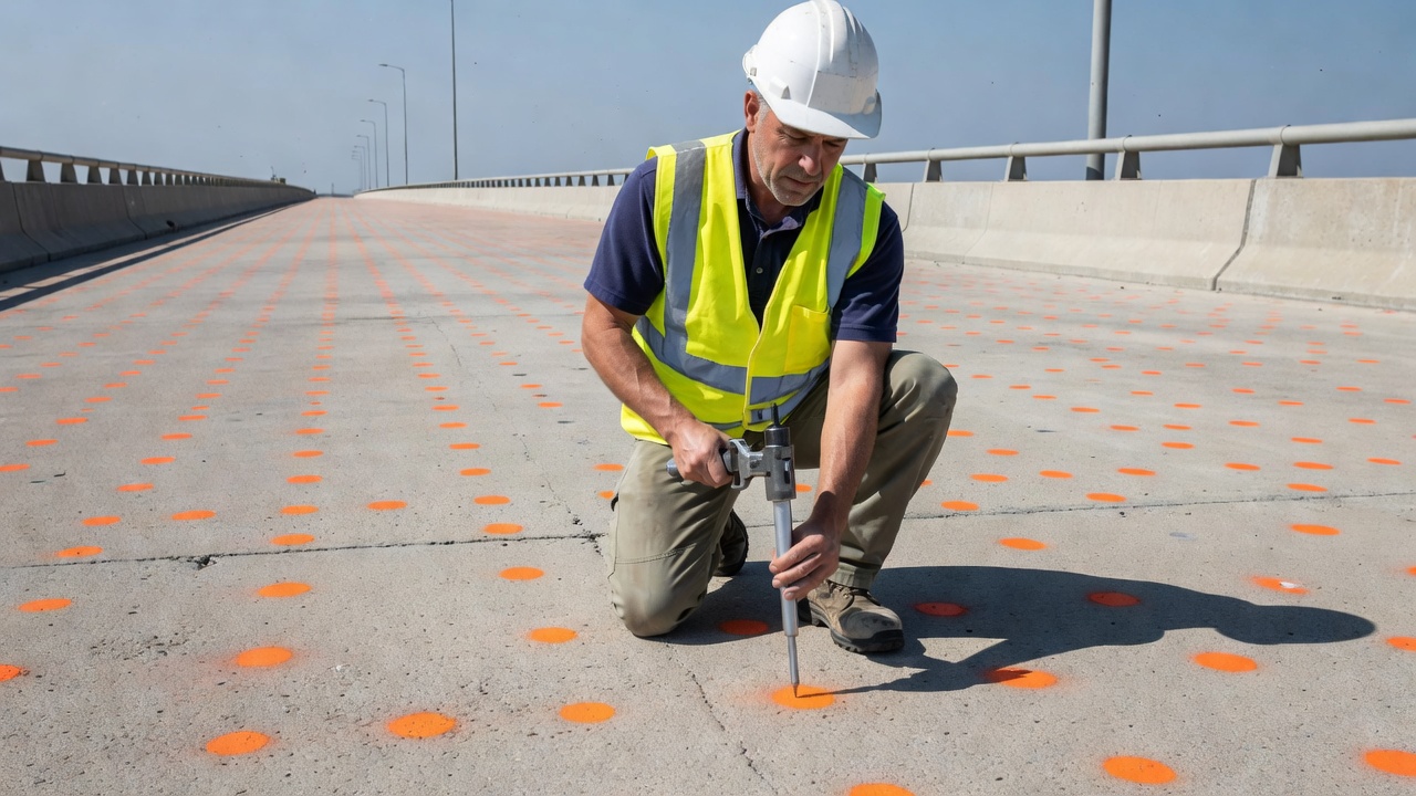
In pavement evaluation, the rebound hammer is used to assess the uniformity of concrete pavement slabs, identify isolated areas of poor-quality concrete, evaluate the effectiveness of curing, and compare different pavement sections. The standard practice involves testing five locations per slab (four corners and center) with 10 readings per location, providing a statistically robust assessment of slab-to-slab variability.
In precast concrete production quality control, the rebound hammer enables rapid, non-destructive verification that all elements in a production run have equivalent surface hardness. Elements with rebound numbers outside acceptable control limits can be identified before shipping and subjected to additional testing.
The rebound hammer is a standard tool in routine bridge inspection programs as defined by the National Bridge Inspection Standards (NBIS) in the United States and equivalent standards internationally (such as the UK Bridge Inspection Manual and Austroads Bridge Inspection Guide). Bridge inspectors use the rebound hammer as part of the condition assessment for concrete substructures (abutments, piers, pier caps, columns) and superstructures (girders, decks, diaphragms).
For bridge inspection applications, the rebound hammer is most valuable as a screening tool that identifies areas warranting closer examination. A typical bridge inspection protocol includes:
The rebound hammer is particularly useful for screening large concrete surfaces where comprehensive coring would be impractical and uneconomical. For a typical highway bridge, 200 to 500 rebound readings can be collected in approximately 2 to 4 hours depending on accessibility, providing a statistically meaningful map of relative concrete quality across the entire structure.
In pavement evaluation for airfields and highways, the rebound hammer is used according to ICAO (International Civil Aviation Organization) and FAA (Federal Aviation Administration) protocols for assessing existing pavement condition during pavement management surveys. The data contributes to the Pavement Condition Index (PCI) calculation by providing quantitative surface hardness data that complements the visual distress survey. ICAO Annex 14 — Aerodromes — requires that pavement surface condition be monitored, and rebound hammer testing provides a measurable indicator of surface quality and deterioration progression over time.
The accuracy and reliability of concrete condition assessment are significantly improved when the rebound hammer is used in combination with other NDT methods. Each method has its own strengths and limitations, and combining them allows the strengths of one method to compensate for the limitations of another.
The SONREB method is the most established combined-NDT approach. It mathematically integrates rebound number (R) and ultrasonic pulse velocity (V) to estimate concrete compressive strength using empirical equations developed for specific concrete types. The fundamental principle is that the rebound number provides surface hardness information while UPV provides internal quality information including density, homogeneity, and the presence of internal defects.
Multi-variable regression equations commonly used in SONREB take the general form:
f’c = a × V^b × R^c
where a, b, and c are empirically determined constants. Different researchers have published various formulations:
| Source | Equation | Applicability |
|---|---|---|
| RILEM (1983) | f’c = 9.27 × 10⁻¹¹ × V².⁶ × R¹.⁵ | General concrete, 10-50 MPa |
| Tanigawa et al. | f’c = 8.47 × 10⁻¹¹ × V².⁴ × R¹.² | Japanese normal-weight concrete |
| Qasrawi (2000) | f’c = 0.074 × V¹.⁵ × R⁰.⁵ | Local calibration, Middle East |
| Di Leo and Pascale | f’c = 12.0 × 10⁻⁴ × V⁰.⁷ × R².² | Italian concrete mixtures |
The SONREB method has been shown to reduce the standard error of estimate from approximately ±20% for rebound-only or UPV-only methods to approximately ±10% to ±12% for the combined method. The European standard EN 13791 provides guidance on the combined approach. No ASTM standard currently exists for SONREB, but ACI 228.1R recognizes the value of combining methods.
The most defensible approach for estimating concrete strength is calibrated rebound hammer testing with selective coring. The process involves:
This approach optimizes the number of cores required — cores are taken only where needed — while maintaining statistical confidence in the strength estimates. The Federal Highway Administration (FHWA) and ACI both recommend this approach for in-place concrete strength evaluation.
| NDT Method | Complementary Value When Combined with Rebound Hammer |
|---|---|
| Ultrasonic Pulse Velocity (UPV) | Provides internal density and homogeneity data; enables SONREB combined analysis |
| Impact Echo (IE) | Detects internal voids, delamination, and thickness variations undetectable by rebound |
| Ground-Penetrating Radar (GPR) | Maps reinforcement location and concrete cover depth to verify testing clearance |
| Half-Cell Potential (HCP) | Identifies active corrosion zones that may produce surface deterioration detectable as low rebound numbers |
| Infrared Thermography (IRT) | Detects subsurface delamination and moisture accumulation affecting surface properties |
| Cover Meter | Verifies reinforcement location to avoid interference with rebound readings |
| Windsor Probe | Provides complementary penetration resistance measurement correlated to strength |
Regular calibration and verification are essential for obtaining reliable rebound hammer measurements. The verification procedure is defined in ASTM C805 and EN 12504-2 and uses a calibration test anvil.
The calibration test anvil is a precision-machined cylinder of tool steel, approximately 150 mm (6 inches) in diameter and 150 mm (6 inches) in height, with the impact area heat-treated to a hardness of 66 ± 2 HRC as measured by ASTM E18 Rockwell hardness test. An instrument guide is typically provided to center the rebound hammer over the impact area and maintain perpendicular orientation. The anvil is a certified reference standard with a documented rebound value — typically 80 ± 2 for a properly functioning Type N hammer.
If the average falls outside the acceptable range (78 to 82 for most hammers), the hammer requires professional servicing — typically including disassembly, cleaning, spring replacement, re-lubrication, and recalibration. Field adjustment of the spring tension or latch mechanism should only be performed by authorized service personnel using certified calibration equipment.
| Condition | Minimum Calibration Frequency |
|---|---|
| Routine field use | Every 2,000 impacts or annually (whichever comes first) |
| Before a critical project | Initial verification on test anvil |
| After a drop or impact | Immediately |
| After maintenance or repair | Immediately |
| When results are questioned | Immediately |
| Formal certification | Annually by manufacturer or certified calibration lab |
A log should be maintained recording the date, operator, hammer serial number, calibration results, and any corrective actions taken for each calibration event. This log provides traceability and quality assurance documentation required for ISO 17025 and many owner specifications.
The Schmidt rebound hammer remains one of the most widely used non-destructive testing instruments for concrete evaluation because of its speed, portability, simplicity, and low cost. It excels as a screening tool for assessing concrete uniformity, identifying areas of potential deterioration, and guiding the selection of core locations. The method is standardized under ASTM C805, EN 12504-2, and ACI 228.1R, which provide clear procedures for testing, calculation, reporting, and calibration.
However, the limitations of the rebound hammer must be understood and respected. It measures only surface properties (outermost 20-30 mm), correlates only approximately with compressive strength (standard error ±15-25%), and is influenced by numerous factors including moisture content, carbonation, aggregate type, surface finish, temperature, and hammer orientation. ASTM C805 explicitly states that the method is not intended for acceptance or rejection of concrete.
The best results are achieved when the rebound hammer is used as part of a comprehensive NDT program that integrates multiple methods. The SONREB method combining rebound hammer with ultrasonic pulse velocity has been shown to significantly improve accuracy. Calibration with selective confirmatory coring provides the most defensible strength estimates. Proper operator training, regular instrument calibration, careful adherence to standard procedures, and informed interpretation of results are essential for obtaining meaningful data.
For infrastructure owners and condition assessment professionals, the rebound hammer is an essential tool — not as a substitute for other testing methods, but as a complementary technique that provides rapid, cost-effective data to guide more detailed investigation and informed decision-making.
TarmacView provides comprehensive concrete inspection solutions including rebound hammer testing, ultrasonic pulse velocity, impact echo, and core sampling for bridges, pavements, and structures. Contact our team of experienced NDT engineers.
Impact-Echo is a stress-wave nondestructive testing method where a short-duration mechanical impact on a concrete surface generates stress waves that reflect fr...
A cover meter, also known as a pachometer or rebar locator, is an electromagnetic NDT device that detects the position, depth, and diameter of reinforcing steel...
Non-Destructive Testing (NDT) encompasses methods to evaluate material properties, detect defects, and assess structural condition without causing damage. For i...