Reconstruction is the complete removal and replacement of a pavement structure from subgrade up, performed when the pavement has reached terminal condition and rehabilitation is no longer cost-effective. Covers full-depth removal, subgrade improvement, new base and surface construction, and the decision point between rehabilitation and reconstruction.
Pavement Reconstruction
Definition and Distinction from Rehabilitation
Pavement reconstruction is the complete removal of an existing pavement structure down to the subgrade and the construction of an entirely new pavement system. It represents the most extensive pavement intervention in the maintenance and rehabilitation hierarchy, reserved for pavements that have reached terminal condition and cannot be cost-effectively restored through lesser interventions.
The term reconstruction carries specific meaning in airport pavement engineering, distinct from rehabilitation and maintenance. According to the FAA Advisory Circular 150/5320-6G, “Airport Pavement Design and Evaluation,” Chapter 4, reconstruction is defined as the process of removing the existing pavement and constructing a new pavement structure in its place. This is fundamentally different from rehabilitation, which involves placing additional structural layers over the existing pavement, typically in the form of asphalt or concrete overlays.
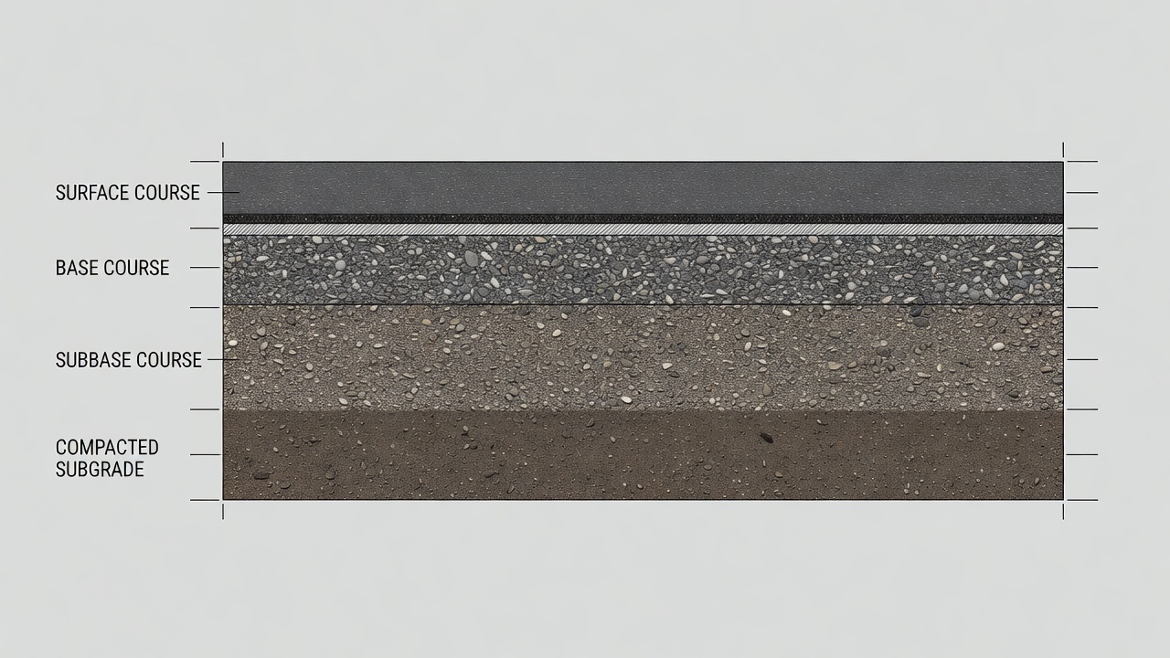
The key distinction between reconstruction and rehabilitation lies in the depth of intervention and the treatment of the existing structure. In rehabilitation, the existing pavement remains in place and becomes part of the new structural section. Methods such as asphalt overlays, concrete overlays (bonded or unbonded), full-depth reclamation (FDR), and rubblization all preserve the existing pavement as a platform for new construction. In reconstruction, every layer from the surface course down through the base, subbase, and sometimes the upper portion of the subgrade is removed and replaced.
The decision between reconstruction and rehabilitation is governed by several factors. When a pavement has been overlayed multiple times, the cumulative overlay thickness may raise the pavement surface elevation beyond acceptable limits for runway lighting, drainage structures, curb heights, and threshold elevations. ICAO Annex 14 specifies allowable elevation tolerances for runway surfaces and adjacent infrastructure, and exceeding these limits through repeated overlays forces reconstruction as the only viable option.
Another determinining factor is the condition of the subgrade. Rehabilitation methods assume that the subgrade retains adequate load-bearing capacity to support the new overlay. When subgrade failure has occurred — evidenced by pumping, excessive rutting, or bearing capacity below design requirements — overlaying a failed subgrade merely transfers structural distress upward through the new layers. Subgrade failure mandates full-depth reconstruction with subgrade improvement.
Material compatibility also dictates the reconstruction decision. When the existing pavement contains materials that are incompatible with overlay materials — such as certain types of aggregate prone to alkali-silica reaction (ASR) or expansive clay subgrades — reconstruction allows for complete removal and replacement with engineered materials. The presence of contaminated materials, such as fuel-saturated asphalt from apron fuel spills, may also require removal and disposal rather than overlay.
From a regulatory standpoint, the FAA and ICAO provide explicit guidance on when reconstruction is appropriate. Per FAA AC 150/5320-6G paragraph 4.4, reconstruction is considered when the existing pavement structure is “no longer capable of supporting anticipated traffic loads” and when “the pavement has reached a level of deterioration that does not warrant the cost of rehabilitation.” ICAO Doc 9157 Part 3 similarly recommends reconstruction when the pavement has “deteriorated beyond the point where structural strengthening is economically justified.”
When Reconstruction is Warranted
Reconstruction is not the default intervention for aging pavement. It is specifically indicated when the pavement has reached a state where rehabilitation would be structurally inadequate, technically impractical, or economically suboptimal. The determination is made through systematic pavement evaluation using standardized condition indices, structural testing, and life-cycle cost analysis.
Pavement Condition Index Thresholds
The Pavement Condition Index (PCI), standardized under ASTM D5340, is the primary tool for assessing pavement condition at airports. PCI is a numerical index ranging from 0 (failed) to 100 (excellent), derived from a visual survey of distress types, severities, and densities. The PCI establishes the condition baseline for determining intervention type.
For flexible (asphalt) pavements, reconstruction is typically indicated when the PCI falls below 25 to 40, depending on the criticality of the pavement. At this stage, distresses are severe and extensive: fatigue (alligator) cracking covering more than 25% of the surface area, rutting exceeding 1 inch (25 mm) in depth, and extensive patching with ongoing deterioration. The FAA pavement management guidance categorizes PCI ranges as follows:
PCI Range
Condition Rating
Typical Intervention
86-100
Excellent
Routine maintenance
71-85
Good
Preventive maintenance
56-70
Fair
Major rehabilitation
41-55
Poor
Heavy rehabilitation
26-40
Very Poor
Reconstruction candidate
0-25
Failed
Reconstruction required
For rigid (concrete) pavements, the threshold for reconstruction is generally higher, with PCI values below 40 to 50 indicating that reconstruction should be evaluated. Concrete pavement deterioration at these levels includes slab cracking with faulting exceeding 0.5 inches (13 mm), corner breaks, durability cracking (D-cracking), and slab pumping with voids beneath the slab. The higher threshold for concrete reflects the difficulty and cost of repairing deteriorated rigid pavements compared to flexible pavements.
The FAA AC 150/5380-6C “Guidelines and Procedures for Maintenance of Airport Pavements” explicitly states that “pavements with a PCI less than 40 should be evaluated for reconstruction” and recommends that the evaluation include a structural assessment to confirm that overlay thickness requirements have not become economically prohibitive.
Structural Failure Indicators
Beyond visual condition surveys, structural evaluation provides quantitative data for the reconstruction decision. The Falling Weight Deflectometer (FWD) is the primary nondestructive testing tool for airport pavement structural evaluation. FWD testing measures the deflection response of the pavement to an impulse load simulating aircraft traffic, from which layer moduli and remaining structural capacity are computed.
Per FAA AC 150/5320-6G Appendix C and ICAO Doc 9157 Part 3 Section 5, structural evaluation for reconstruction decisions considers:
Deflection Basins: Pavements with high center deflections (exceeding 0.040 inches or 1.0 mm for typical airfield pavements under standard FWD loading of 9,000 to 12,000 pounds per wheel) and flat basin shapes indicate deep structural weakness requiring reconstruction.
Layer Moduli Back-Calculation: Using FWD data, the elastic moduli of each pavement layer are computed. When the existing asphalt modulus falls below 100,000 psi (690 MPa) at standard temperature, or the concrete modulus drops below 2,000,000 psi (13,800 MPa), the material has undergone significant degradation and reconstruction may be more cost-effective than overlay.
Remaining Life Analysis: FAARFIELD, the FAA’s airport pavement design software, calculates remaining structural life based on accumulated damage (Cumulative Damage Factor or CDF). When CDF exceeds 1.0 at the design traffic level, the pavement has exceeded its structural design life. When CDF exceeds 1.5 to 2.0, significant structural deterioration is underway and reconstruction becomes the preferred option.
Layer Thinning: Ground Penetrating Radar (GPR) and coring data establish existing layer thicknesses. When the remaining asphalt thickness is less than 3 inches (75 mm) or concrete thickness is less than 6 inches (150 mm), overlay thickness requirements become large and reconstruction may be more economical.
Subgrade Failure
Subgrade failure is perhaps the most definitive indicator that reconstruction is required. Rehabilitation methods — including overlays, FDR, and rubblization — all rely on the existing subgrade to provide adequate foundation support. When the subgrade itself has failed, these interventions will not succeed regardless of the thickness or quality of the new surface layers.
Subgrade failure manifests through several distress mechanisms visible at the surface:
Pumping: The expulsion of fine soil particles from the subgrade through pavement joints, cracks, or along pavement edges, visible as surface staining or soil deposits. Pumping indicates that the subgrade has been weakened by water saturation and repeated loading, eroding the foundation support.
Rutting: Structural rutting (as distinct from surface-course rutting from asphalt instability) extends through the full pavement thickness and indicates permanent deformation in the subgrade. Rut depths exceeding 1 inch (25 mm) that are consistent across the pavement width suggest subgrade failure.
Subgrade Moisture Content: Testing of subgrade soils reveals elevated moisture content relative to optimum, indicating inadequate drainage or capillary rise. When the subgrade moisture content exceeds the plastic limit or the in-situ density falls below 90% of maximum dry density (per ASTM D698 or D1557), subgrade improvement through reconstruction is necessary.
California Bearing Ratio (CBR): Subgrade CBR values below 3 for flexible pavements or below 5 for rigid pavements indicate insufficient bearing capacity for even heavy rehabilitation. Reconstruction with subgrade improvement — either through over-excavation, stabilization, or geosynthetic reinforcement — is required to achieve design CBR values of 5 to 15 for airfield pavements.
Frost Heave: In cold climates, frost-susceptible subgrade soils (classified in FAA Frost Group F4) experience differential frost heave and spring thaw weakening. When existing subgrade soils are frost-susceptible and frost penetration exceeds 24 inches (600 mm), reconstruction with frost-free subgrade depth or insulation is indicated.
The ICAO Aerodrome Design Manual Part 3 Section 2.4.3 states that “when the subgrade has been weakened by water or has suffered significant permanent deformation, reconstruction with incorporation of appropriate drainage and subgrade stabilization measures should be considered.”
Reconstruction Process Stages
Pavement reconstruction follows a systematic sequence of stages, each with specific technical requirements, quality control procedures, and acceptance criteria. The process is governed by contract specifications that reference FAA AC 150/5370-10 “Standard Specifications for Construction of Airports” and applicable ASTM, AASHTO, and ICAO standards.
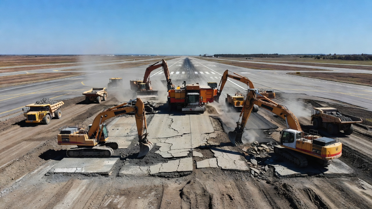
Stage 1: Demolition and Removal
The reconstruction process begins with the complete removal of existing pavement layers. Full-depth removal encompasses the surface course (asphalt or concrete), base course, and subbase course, down to the specified subgrade elevation. The demolition method depends on the pavement type:
Asphalt Pavement Removal: Asphalt layers are typically removed using cold planing (milling) machines with drum widths of 6 to 12 feet (1.8 to 3.7 meters) capable of cutting depths up to 12 inches (300 mm) per pass. For full-depth removal, multiple passes may be required. Ripping with heavy dozers and excavator-mounted hydraulic hammers is used for thick sections. The milled material (Reclaimed Asphalt Pavement or RAP) is loaded into trucks for transport to stockpile or recycling facilities.
Concrete Pavement Removal: Rigid pavement removal requires heavier equipment. Concrete slabs are typically broken using pneumatic hammers, hydraulic breakers mounted on excavators, or resonant breakers. Large concrete pieces are loaded for disposal or crushing. Reinforced concrete requires cutting or torch removal of exposed rebar. Dowel bars and tie bars at joints are cut or extracted.
Selective vs. Full Removal: In some reconstruction projects, only the upper portion of the base course is removed if the lower base and subbase are sound. The design specifications define the removal depth based on coring data and structural evaluation. When contamination (fuel, oil, or chemical spills) has penetrated the pavement, full-depth removal is mandatory.
Material Classification and Disposal: Removed materials are classified for disposal or recycling. Clean concrete and asphalt can be crushed for use as aggregate base in the new pavement or for other construction applications. Testing for hazardous materials (asbestos, lead, contaminated soils) must be conducted before disposal. Per FAA AC 150/5370-10, RAP may be incorporated into new hot-mix asphalt at up to 30% by weight unless otherwise specified.
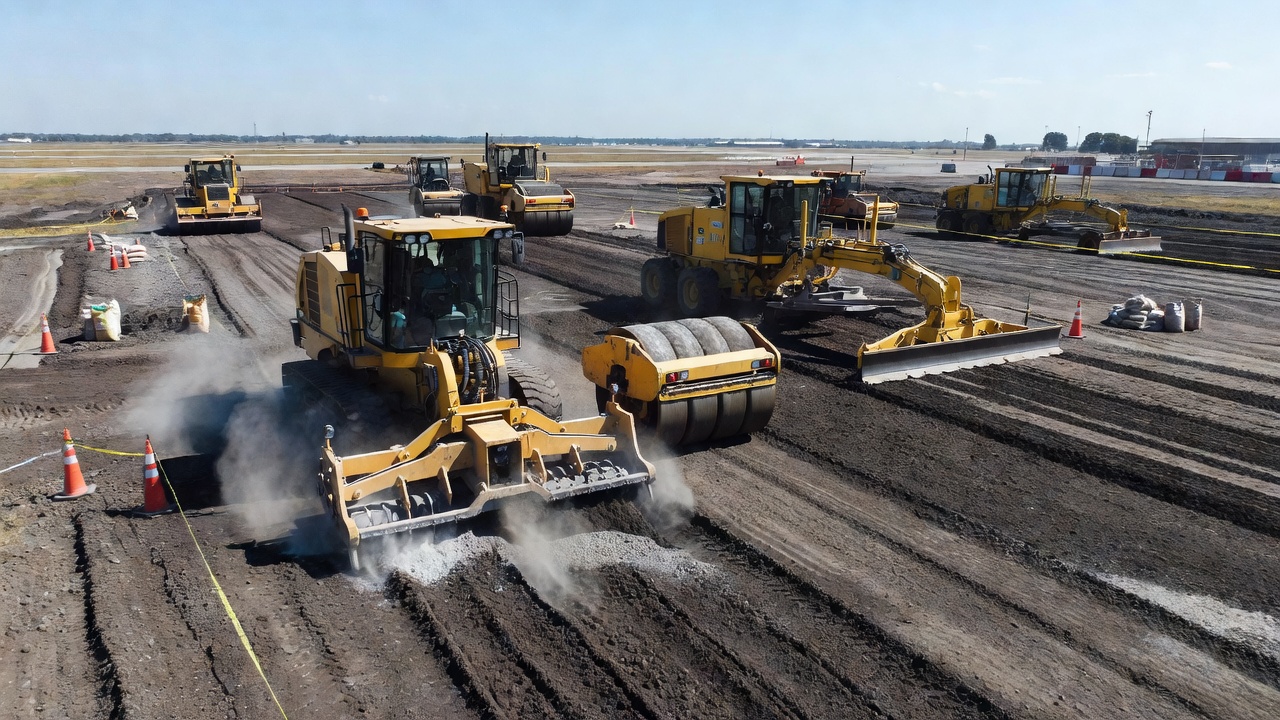
Stage 2: Subgrade Preparation
After removal of existing pavement layers, the exposed subgrade surface is evaluated, repaired, and prepared to receive the new pavement structure. This stage is critical because the new pavement will depend entirely on the subgrade for foundation support.
Subgrade Evaluation: The exposed subgrade is tested for density, moisture content, and bearing capacity. In-situ density is measured using nuclear density gauges or sand cone tests (ASTM D1556). CBR or dynamic cone penetrometer (DCP) tests evaluate bearing capacity. Per FAA AC 150/5320-6G Appendix D, DCP testing provides rapid assessment of subgrade strength for quality control during construction.
Proof Rolling: A heavy rubber-tired roller loaded to at least 25 tons (or equivalent) is passed over the subgrade surface to identify soft spots, pumping areas, or zones of inadequate support. Areas that deflect, rut, or pump under proof rolling are marked for over-excavation and replacement.
Over-Excavation: Weak or unsuitable subgrade soil is excavated to a depth of 12 to 36 inches (300 to 900 mm) or until competent material is reached. The excavation is backfilled with approved granular fill, stabilized soil, or geosynthetic-reinforced soil, compacted to at least 95% of maximum dry density (ASTM D698 or D1557).
Compaction: The subgrade is compacted to the specified density, typically 95% to 100% of maximum dry density (Standard Proctor, ASTM D698) for the top 6 inches (150 mm), and 90% to 95% for deeper lifts. Moisture content is controlled to within 2% of optimum moisture content. Per FAA specification P-152 (Subgrade), compaction requirements vary by soil type and frost zone.
Drainage Installation: Subsurface drainage systems, including edge drains, collector pipes, and outlet structures, are installed at the subgrade level before base course construction. Perforated pipe drains wrapped in geotextile filter fabric are placed in trenches excavated at the pavement edges, graded to outlet at a minimum slope of 0.5%.
Stage 3: Subbase and Base Course Construction
With the subgrade prepared, the subbase and base courses are constructed in lifts, each compacted to specified density and thickness.
Subbase Course: The subbase provides an additional load distribution layer and separates the base course from the subgrade. Materials typically include granular aggregates (crushed stone, gravel, or sand) meeting FAA P-154 or P-208 specifications, or stabilized materials such as cement-treated subbase (P-301) or asphalt-treated subbase (P-401). Minimum compacted thickness is typically 6 inches (150 mm) for granular subbase and 4 inches (100 mm) for treated subbase.
Base Course: The base is the primary structural layer beneath the surface course. For flexible pavements, base course options include crushed aggregate base (P-209), asphalt-treated base (P-401), cement-treated base (P-304), or lean concrete base (P-306). For rigid pavements, the base may be a cement-treated or asphalt-treated layer providing uniform support and preventing slab pumping.
Lift Thickness: Granular materials are placed in lifts not exceeding 6 to 8 inches (150 to 200 mm) loose thickness, compacted to the specified density. Treated materials may be placed in lifts up to 8 to 12 inches (200 to 300 mm) depending on the equipment. Each lift is tested for density, grade, and thickness before the next lift is placed.
Stage 4: Surface Course Construction
The surface course is the final structural layer and the traffic-bearing surface. The choice between flexible (asphalt) and rigid (concrete) surface is based on design, operational, and economic considerations.
Flexible Surface (Asphalt): Hot-mix asphalt (HMA) surface course is placed per FAA P-401 specifications. The mix design (Marshall or Superpave) is developed from job-mix formulas with aggregates and binder meeting gradation and quality requirements. Placement temperature ranges from 275°F to 325°F (135°C to 163°C) for conventional HMA. Compaction achieves at least 96% of laboratory density. Surface smoothness is controlled to a maximum deviation of 1/8 inch (3 mm) under a 16-foot (4.9 m) straightedge.
Rigid Surface (Concrete): Portland cement concrete (PCC) surface is placed per FAA P-501 specifications. Concrete mix design achieves a minimum 28-day compressive strength of 4,000 to 5,500 psi (27.6 to 37.9 MPa) depending on design requirements. Slipform paving places concrete in slabs typically 12 to 18 inches (300 to 450 mm) thick for primary runways. Joints are saw-cut within 4 to 12 hours of placement to control cracking. Surface texturing (burlap drag, wire combing, or tining) provides friction, and transverse grooving is applied at 1/4 inch (6 mm) depth and spacing to prevent hydroplaning.
Stage 5: Finishing and Ancillary Work
The final stage includes surface grooving, installation of lighting and markings, and quality acceptance testing.
Grooving: For asphalt and concrete surfaces, transverse or longitudinal grooves are cut at 1/4 inch (6 mm) width, 1/4 inch (6 mm) depth, and 1.25 to 1.5 inch (32 to 38 mm) spacing to maintain friction and channel water.
Lighting Installation: Runway, taxiway, and apron lighting fixtures are installed flush with the new pavement surface. Light bases are set in concrete collars, and conduit is embedded in the base or subbase course during construction.
Markings: New pavement markings are applied per ICAO Annex 14 and FAA AC 150/5340-1 standards. Runway markings are white; taxiway markings are yellow. Reflective glass beads are incorporated for night visibility.
Subgrade Improvement and Stabilization
Subgrade improvement is a critical component of reconstruction, often distinguishing it from lesser rehabilitation methods. When pavement reconstruction reaches the subgrade, there is an opportunity — and frequently a requirement — to improve the foundation soil beyond its natural condition.
Mechanical Stabilization: This involves changing the physical properties of the subgrade through compaction, blending, or reinforcement. Deep dynamic compaction uses heavy drop weights to densify deep soil layers. Vibro-compaction or vibro-replacement (stone columns) installs columns of compacted granular material through weak soils to improve bearing capacity and reduce settlement.
Chemical Stabilization: Subgrade soils with inadequate strength, high plasticity, or moisture sensitivity are treated with chemical additives. Lime stabilization (3% to 8% by dry weight of soil) reduces plasticity index, improves workability, and increases strength of clay soils through cation exchange and pozzolanic reactions. Cement stabilization (3% to 8% by dry weight of soil) binds soil particles through cementitious hydration, significantly increasing strength and stiffness. Fly ash and ground granulated blast furnace slag (GGBFS) are used as supplementary binders to reduce cost and environmental impact.
Geosynthetic Reinforcement: Geotextiles and geogrids are placed between the subgrade and subbase to improve load distribution, reduce aggregate penetration into soft subgrade, and increase the structural number of the pavement section. For airport pavements, geogrids with a minimum tensile strength of 2,400 lbs/ft (35 kN/m) are typically specified.
Drainage Improvement: Subgrade improvement nearly always includes drainage enhancement. Lateral drains, interceptor drains, blanket drains (permeable layers of granular material), and daylighting outlets ensure that water does not accumulate in the subgrade. The FAA requires that “positive drainage of the subgrade shall be provided” in reconstruction projects (AC 150/5320-6G Section 2.4).
The FAA AC 150/5320-6G Table 3-1 provides recommended treatment methods for swelling soils, categorized by the potential swell (low, marginal, high, very high) and the required level of treatment.
Reconstruction Materials and Specifications
Materials used in reconstruction must comply with FAA, ICAO, and national standards for airport pavements. The material selection for each layer is specified in the contract documents based on design requirements.
Pavement Layer
Material Type
FAA Specification
Key Requirements
Subgrade
Natural soil, stabilized soil
P-152, P-154
95% compaction, CBR ≥ 3-5
Subbase
Crushed aggregate, stabilized aggregate
P-208, P-209, P-301
CBR ≥ 20-30, LL < 25, PI < 6
Base (Flexible)
Crushed stone, ATB, CTB
P-209, P-401, P-304
CBR ≥ 80, min 4" thickness
Surface (Asphalt)
HMA, SMA, PMA
P-401
96% compaction, 4,000+ psi stability
Surface (Concrete)
PCC, RCC
P-501, P-502
4,000-5,500 psi 28-day, air content 4-7%
Shoulder
Aggregate, stabilized
P-208, P-304
Lighter loading than primary area
Hot-Mix Asphalt (P-401): The predominant surface material for flexible airport pavements. HMA consists of 94% to 96% aggregates (by weight) and 4% to 6% binder (asphalt cement). Polymer-modified binders (PMB) are increasingly specified for high-traffic runways and aprons to improve rutting resistance at high temperatures and cracking resistance at low temperatures. The FAA requires all HMA for airfield pavements to meet P-401 specifications, including maximum 3.0% air voids and minimum 92% voids in mineral aggregate (VMA) for surface courses.
Portland Cement Concrete (P-501): The primary rigid pavement material. PCC for airport pavements uses a minimum of 560 lbs/yd³ (332 kg/m³) of Type I or Type II Portland cement, coarse aggregate of 1.5-inch (38 mm) nominal maximum size, and fine aggregate meeting FAA gradation requirements. Air-entraining admixtures are required at 4% to 7% air content for freeze-thaw protection. Water-cement ratio is limited to 0.40 to 0.45 to achieve low permeability and high durability.
Cement-Treated Base (P-304): A mixture of granular aggregate, Portland cement (3% to 8%), and water, compacted and cured to form a rigid base layer. Unconfined compressive strength at 7 days is typically 300 to 600 psi (2.1 to 4.1 MPa). CTB provides excellent load distribution and prevents subgrade pumping beneath concrete pavements.
Lean Concrete Base (P-306): A low-cement-content concrete (typically 250 to 350 lbs/yd³ or 148 to 208 kg/m³) used as a rigid base beneath concrete surface courses. Slump is controlled to 1 inch (25 mm) or less. Compressive strength ranges from 750 to 1,500 psi (5.2 to 10.3 MPa) at 28 days.
The FAA AC 150/5370-10 (Standard Specifications for Construction of Airports) provides detailed material requirements, testing procedures, and acceptance criteria for each specification item. The 2023 edition (AC 150/5370-10H) contains updated provisions for recycled materials, warm-mix asphalt, and performance-related specifications.
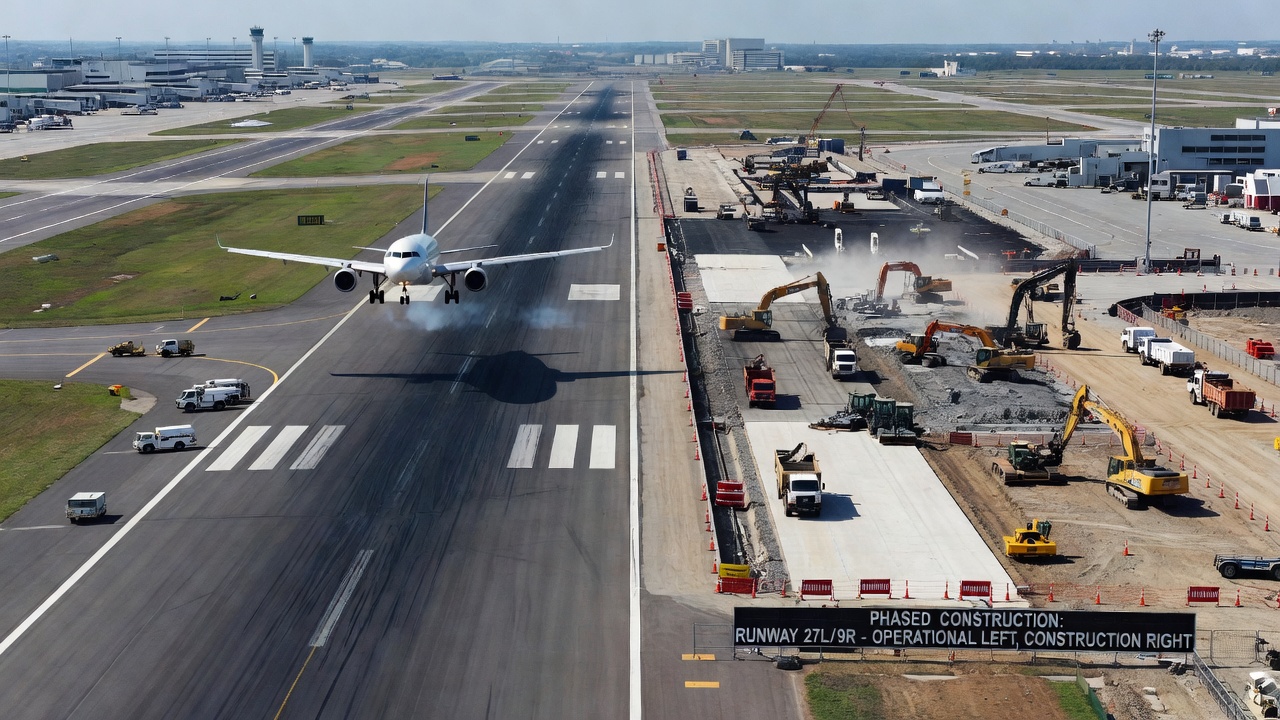
Airport Pavement Reconstruction — Phasing and Operational Constraints
Reconstruction of an active airport pavement — runway, taxiway, or apron — while maintaining air traffic operations presents unique engineering and operational challenges not encountered in highway reconstruction. The requirement to keep the airport operational during construction imposes constraints on sequencing, scheduling, safety, and aircraft operations.
Phasing Strategies
Longitudinal Phasing: The most common approach for runway reconstruction divides the runway into two or three longitudinal sections constructed sequentially. In a two-phase operation, one half of the runway width (typically 75 feet or 23 meters for a 150-foot or 45-meter wide runway) is reconstructed while the opposite half remains operational at a reduced width. This requires that the operational half provides sufficient width for aircraft operations, typically a minimum of 75 feet (23 meters) for Code C aircraft and 100 feet (30 meters) for Code D and E aircraft as specified in ICAO Annex 14 Table 3-1.
Transverse Phasing: For shorter runways or when longitudinal phasing is impractical, the runway may be divided transversely into sections. In this approach, the full width of a runway section (for example, the first 3,000 feet or 915 meters) is reconstructed while aircraft use the remaining length. Displaced thresholds are established, reducing the declared distances (TODA, ASDA, LDA) and potentially restricting aircraft types that can operate.
Sequential Section Phasing: The runway is divided into several transverse sections (typically 1,000 to 2,000 feet or 300 to 600 meters each), reconstructed sequentially. As each section is completed, reconstruction moves to the next section while aircraft use the completed portions. This approach requires multiple relocations of temporary thresholds and lighting systems.
Night and Weekend Construction: To minimize operational disruption, reconstruction work is concentrated during nighttime low-traffic periods or weekend closures. This imposes production constraints requiring adequate planning for material supply, crew scheduling, and curing times. Concrete pavement reconstruction is particularly challenging for night-only work due to the minimum 7-day curing time before opening to traffic.
Operational Constraints
Declared Distances: During phased reconstruction, the declared distances — Takeoff Run Available (TORA), Takeoff Distance Available (TODA), Accelerate-Stop Distance Available (ASDA), and Landing Distance Available (LDA) — are reduced to reflect the available runway length. These reductions are published in NOTAMs (Notices to Airmen) and Aeronautical Information Publications (AIPs).
Runway Strip Requirements: The reconstruction zone must maintain a safe separation from the operational runway. ICAO Annex 14 requires that the runway strip — graded and cleared area extending 150 feet (45 meters) for Code 3 and 4 runways — be maintained on the operational side. Construction equipment, stockpiles, and personnel must not penetrate the obstacle limitation surfaces (OLS) for the operational runway.
Jet Blast Considerations: Construction equipment and personnel near the operational runway must be protected from jet blast. The ICAO Aerodrome Design Manual Part 2 Section 7.3 provides exhaust velocity contours for aircraft at various thrust settings. Construction zones must be located outside the jet blast hazard area, typically 200 to 500 feet (60 to 150 meters) behind the taxiing or holding aircraft.
Lighting and Marking: Temporary lighting systems (L-880, L-881, L-882 types per FAA AC 150/5340-30) must be installed when permanent lighting is disrupted during reconstruction. Temporary markings conforming to ICAO Annex 14 standards are required. The interface between reconstructed and unreconstructed sections must be clearly delineated with temporary markings and lighting.
Air Traffic Control Coordination: Reconstruction phasing requires approval through aeronautical studies and coordination with air traffic control. ICAO Doc 9157 Part 3 and the “Airport Operations in Conjunction with Construction Work” guidance establish procedures for safe operations during construction.
NOTAM Publication: All changes to runway availability, widths, declared distances, and lighting status require NOTAM publication at minimum 72 hours in advance for significant changes. The Aeronautical Information Regulation and Control (AIRAC) system may require notification 28 days in advance for major changes to instrument approach procedures.
Cost Comparison with Rehabilitation
The economic decision between reconstruction and rehabilitation is driven by life-cycle cost analysis (LCCA) that considers initial construction cost, service life, maintenance costs, and user costs (operational disruption). The FAA requires LCCA for all federally funded pavement projects per AC 150/5320-6G Section 1.2(c).
Initial Construction Cost: Reconstruction typically costs 2 to 4 times the initial cost of an overlay rehabilitation for the same pavement area. Based on FAA and industry data for 2024:
Intervention Type
Typical Unit Cost (per square yard)
Cost per 1,000 ft x 150 ft runway
4-inch Asphalt Overlay
$8-15
$133,000 - $250,000
6-inch Asphalt Overlay
$12-22
$200,000 - $367,000
Full-Depth Reclamation
$6-12
$100,000 - $200,000
Asphalt Reconstruction (full depth)
$25-50
$417,000 - $833,000
Concrete Reconstruction (12-inch)
$30-65
$500,000 - $1,083,000
These costs exclude subgrade improvement, which can add $5 to $15 per square yard depending on the extent of over-excavation and stabilization required. For runways with significant subgrade issues, total reconstruction costs may approach $60 to $80 per square yard.
Life-Cycle Cost: While reconstruction has a higher initial cost, its service life of 20 to 30 years (versus 10 to 15 years for an overlay) and lower annual maintenance requirements often produce a comparable or lower annualized cost. The FAA’s standard LCCA period is 20 years for flexible pavements and 30 years for rigid pavements.
User Costs: The primary economic advantage of rehabilitation is shorter construction time and less operational disruption. An overlay can typically be completed in 30% to 50% of the time required for full reconstruction. For a busy commercial airport, the cost of operational disruption — reduced capacity, flight delays, airline schedule changes — can far exceed the construction cost. The FAA LCCA guidance requires inclusion of user delay costs for projects at airports with annual traffic exceeding 200,000 aircraft operations.
Agency Cost Savings: Over a 40-year analysis period, three overlays (at 13-year intervals each) would cost approximately $400 to $660 per square yard in total project costs. One reconstruction followed by one overlay would cost approximately $425 to $775 per square yard. The breakeven point depends on the condition of the existing pavement, traffic levels, and discount rates typically set at 3% to 5% for FAA projects.
Decision Matrix: The FAA recommends using a benefit-cost ratio (BCR) for reconstruction decisions. Reconstruction is justified when the BCR exceeds 1.0 and when the BCR for reconstruction exceeds the BCR for the best rehabilitation alternative.
Post-Reconstruction Performance
A properly designed and constructed reconstruction should achieve a service life of 20 to 30 years with appropriate routine maintenance. Performance expectations after reconstruction are defined by design parameters, construction quality, and subsequent maintenance practices.
Expected Performance Parameters: For flexible pavement reconstruction, the expected performance includes a PCI rating above 85 in the first five years, requiring only routine maintenance such as crack sealing and minor patching. Rutting should not exceed 0.25 inch (6 mm) in the first 10 years. Surface friction values should meet or exceed the minimum acceptable levels defined by ICAO (minimum friction coefficient of 0.50 for runways at 40 mph or 65 km/h wet testing).
For rigid pavement reconstruction, joint faulting should not exceed 0.125 inch (3 mm) in the first 10 years. Corner spalling and slab cracking should be minimal — less than 5% of slabs affected in the first 10 years. Average joint sealant life is 5 to 10 years before replacement.
Performance Monitoring: After reconstruction, the pavement enters the airport’s Pavement Management System (PMS) for regular monitoring. Annual PCI surveys (ASTM D5340) track condition deterioration. FWD testing at 5-year intervals or after 50,000 to 100,000 aircraft passes evaluates remaining structural capacity.
Performance Expectations by Pavement Type: The following table summarizes typical post-reconstruction service life expectations from FAA pavement design guidance:
Performance Measure
Asphalt Reconstruction
Concrete Reconstruction
Time to first maintenance
5-8 years (crack sealing)
8-12 years (joint resealing)
Time to first major rehabilitation
15-20 years
20-30 years
Expected structural life
20-30 years
30-40 years
Annual PCI loss
2-4 points/year
1-3 points/year
Major distress type
Fatigue cracking
Joint faulting
Inspection After Reconstruction
Quality assurance inspection during reconstruction is governed by the contract specifications and applicable FAA, ASTM, and AASHTO standards. Inspection activities encompass materials testing, in-process construction control, and final acceptance testing.
Materials Testing: Before placement, each material is tested for compliance with specifications:
Temperature (HMA placement and compaction temperature windows: 280°F to 320°F or 140°C to 160°C typical)
Compaction (nuclear density gauge at specified frequency — typically 1 test per 500 to 1,000 square yards or 400 to 800 square meters)
Surface smoothness (rolling straightedge 16-foot or 4.9-meter, profilograph)
Grade and crown (surveyed cross-sections)
Joint construction (saw-cut timing, joint spacing, sealant installation)
Acceptance Testing: Final acceptance requires:
Smoothness: Not exceeding 1/4 inch (6 mm) deviation under 16-foot (4.9 m) straightedge, or a profile index of less than 5 inches per mile (80 mm/km) per FAA P-401 and P-501.
Density: Each lift tested at minimum 1 test per 500 square yards (418 m²), with results maintained at 95% to 100% of target density.
Thickness: Cores taken (minimum 3 per 1,000 square yards or 836 m²) to verify layer thicknesses within ±1/4 inch (6 mm) of design.
Friction: Macrotexture depth (sand patch test or laser profilometer) minimum 0.03 inch (0.8 mm). Friction testing (continuous friction-measuring equipment or decelerometer) meeting ICAO threshold values.
Documentation: All inspection results are documented in project records including daily construction reports, material test reports, density logs, smoothness profiles, and as-built records. The FAA requires that “a complete set of construction records and as-built drawings be submitted to the owner at project completion” (AC 150/5370-10 Section 100).
Warranty: Some reconstruction projects include warranty provisions requiring the contractor to correct defects for 3 to 5 years after construction. Performance-based warranties specify acceptable levels of distress, rutting, faulting, and smoothness retention.
Post-Construction Inspection: Within the first year after construction, a comprehensive inspection documents any early distress such as:
Surface cracking (thermal, reflective, fatigue)
Joint deterioration (concrete pavements)
Surface wear (loss of texture, raveling)
Drainage performance (ponding, erosion at outlets)
Lighting and marking integrity
Per FAA AC 150/5380-6C, a formal pavement condition survey should be conducted within the first year of completion to establish the baseline PCI for the pavement management system.
The decision to reconstruct rather than rehabilitate is never taken lightly due to the substantial investment involved. However, when the pavement has reached terminal condition with subgrade failure, multiple previous overlays, or PCI values below 25 to 40, reconstruction provides the only technically sound path to restoring full structural capacity and achieving another 20 to 30 years of service life. The key to a successful reconstruction project lies in thorough pre-construction evaluation, proper material selection and quality control during construction, and ongoing performance monitoring after completion to maximize the return on this significant infrastructure investment.
Frequently Asked Questions
Pavement reconstruction is the complete removal and replacement of the entire pavement structure, from the surface course down to the subgrade. Unlike rehabilitation, which preserves and extends the life of existing pavement, reconstruction starts fresh by excavating all existing layers, improving the subgrade if necessary, and constructing an entirely new pavement designed for current aircraft loads and traffic demands.
Reconstruction is warranted when the Pavement Condition Index (PCI) falls below approximately 25 for asphalt and 40 for concrete, when structural failure exists on the subgrade level, when the pavement has reached terminal condition at the end of its service life, or when multiple overlays have raised the pavement elevation beyond acceptable limits for adjacent infrastructure such as lighting, drains, and curb heights.
The reconstruction process includes: (1) full-depth demolition and removal of existing pavement layers, (2) subgrade evaluation and improvement through compaction, stabilization, or over-excavation, (3) construction of new subbase and base courses, (4) placement and compaction of the new surface course (asphalt or concrete), and (5) installation of surface treatments, markings, and lighting.
Reconstruction typically costs 2 to 4 times more than overlay rehabilitation due to full-depth removal, material disposal, subgrade treatment, and complete new construction. However, reconstruction provides a new 20-30 year service life, while overlays typically add only 10-15 years. Life-cycle cost analysis often favors reconstruction when existing pavement is severely deteriorated and multiple overlays would otherwise be needed.
Airport runway reconstruction requires careful phasing to maintain operational capability, often using partial-width construction where half the runway remains open while the other half is rebuilt. Threshold displacement, night-only construction windows, temporary lighting and markings, coordination with air traffic control, and strict adherence to ICAO Annex 14 obstacle limitation surfaces are critical constraints unique to airfield reconstruction projects.
Plan Your Pavement Reconstruction Project
Ensure your airport pavement reconstruction meets ICAO and FAA standards with expert planning, material selection, and quality control. Our specialists can help you determine when reconstruction is warranted and guide you through every stage of the process.
Reconstruction is the complete removal and replacement of a pavement structure from subgrade up, performed when the pavement has reached terminal condition and ...
Pavement rehabilitation encompasses major structural improvements to extend pavement service life beyond routine maintenance. It includes overlays, milling and ...
An asphalt overlay is the placement of one or more new HMA layers over an existing pavement to restore structural capacity, improve ride quality, and/or enhance...
17 min read
pavement-rehabilitation
Asphalt Overlay
+2
Cookie Consent We use cookies to enhance your browsing experience and analyze our traffic. See our privacy policy.