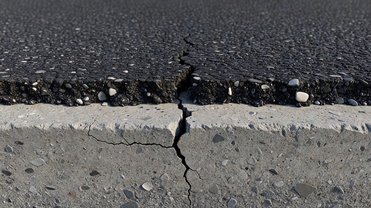
Reflective cracking occurs when cracks or joints in an underlying concrete or stabilized base propagate upward through an asphalt overlay. It is one of the most common distress types in composite and rehabilitated pavements. Covers mechanisms, prevention (stress-absorbing membrane interlayers, geotextiles, thick overlays), and detection in overlay inspection.
Reflective Cracking in Asphalt Overlays
Reflective cracking is a distress mechanism that ranks among the most persistent and costly challenges in pavement rehabilitation engineering. When a new asphalt concrete overlay is placed over an existing pavement containing cracks, joints, or other discontinuities, those underlying discontinuities do not simply disappear — they concentrate stress at their tips, and over time, driven by the combined effects of traffic loading and thermal cycling, cracks propagate upward through the newly constructed overlay until they become visible at the surface. The result is a rehabilitated pavement that may begin to exhibit cracking distress within one to five years of placement, long before the design life of the overlay has been reached.
This glossary entry provides a comprehensive technical reference on reflective cracking, covering its fundamental mechanisms, the distinction between joint reflection and crack reflection, the factors governing crack propagation rate, established and emerging prevention technologies, severity measurement standards, special considerations for airport pavements, the role of artificial intelligence in detection and assessment, and rehabilitation alternatives for pavements already affected by this distress.
1. Definition and Mechanism of Reflective Cracking
Reflective cracking is defined as the propagation of cracks or joints from an existing pavement layer into a new overlay placed above it. The term captures the essence of the phenomenon: the crack pattern in the overlay reflects the pattern of discontinuities in the underlying layer. This distress type is most commonly observed in composite pavement systems — where an asphalt concrete overlay has been placed on a Portland cement concrete (PCC) pavement — but it also occurs when asphalt overlays are placed over deteriorated asphalt pavements, cement-stabilized bases, or other semi-rigid foundation layers.
The physical mechanism of reflective cracking is governed by fracture mechanics principles. At the tip of every existing crack or joint in the underlying pavement, there exists a stress concentration — a localized region where the applied stress is amplified relative to the far-field stress in the surrounding material. When traffic loads or thermal strains are applied to the pavement system, the stress intensity at these crack tips can exceed the tensile strength or fracture toughness of the asphalt overlay material, initiating a new crack that propagates upward through the overlay.
Three distinct modes of loading contribute to reflective cracking, corresponding to the three classical fracture mechanics modes. Mode I (Opening Mode) occurs when tensile stresses develop at the bottom of the overlay directly above the existing crack, typically from traffic-induced bending or thermal contraction of the underlying slab. This is the most common and extensively studied mechanism. Mode II (Sliding/Shear Mode) occurs when differential vertical deflections across the existing crack create shear stresses in the overlay, particularly when load transfer efficiency (LTE) across the joint or crack is poor. Mode III (Tearing Mode) is less common in pavements but can occur under lateral displacement due to subgrade instability or unusual loading conditions.
The crack initiation and propagation process can follow different paths depending on the dominant mechanism. Under thermal loading, cracking may initiate at both the top and bottom of the overlay simultaneously and propagate toward the middle, a phenomenon documented by Joseph and Haas (1989) in Transportation Research Record 1215. Under traffic loading with good load transfer, cracking typically initiates at the bottom of the overlay and propagates upward. Under combined thermal and traffic loading, complex stress distributions develop through the overlay depth, with tensile and compressive zones alternating depending on the relative magnitude and timing of each loading component.
From a fracture mechanics perspective, crack propagation in asphalt overlays is modeled using Paris-Erdogan’s Law, which relates the rate of crack growth per loading cycle (dc/dN) to the amplitude of the stress intensity factor (ΔK): dc/dN = A(ΔK)^n, where A and n are material fracture parameters determined from the creep compliance and tensile strength of the asphalt mixture. For thermally induced cracking, the same relationship is applied with thermal cycles replacing traffic cycles (dc/dT). The total damage is calculated using Miner’s linear cumulative damage hypothesis, summing damage from bending, shear, and thermal mechanisms independently. This approach forms the basis of the reflective cracking model implemented in the AASHTO Pavement ME Design procedure.
2. Joint Reflection Cracking versus Crack Reflection Cracking
While the underlying mechanics are identical, pavement engineers distinguish between two subtypes of reflective cracking based on the nature of the discontinuity in the existing pavement: joint reflection cracking and crack reflection cracking. This distinction has practical implications for overlay design, as the two types exhibit different patterns, propagation rates, and responses to mitigation treatments.
Joint reflection cracking occurs when an asphalt overlay is placed over a jointed Portland cement concrete (JPCC) pavement. The joints in the concrete — whether expansion joints, contraction joints, or construction joints — represent deliberate discontinuities in the pavement structure. These joints are typically straight, regularly spaced at intervals matching the concrete slab dimensions (commonly 3.7 to 6.1 meters or 12 to 20 feet), and oriented transversely and longitudinally to the pavement centerline. When these joints reflect through the overlay, the resulting cracks are characteristically straight, linear, and regularly spaced. Joint reflection cracking produces a grid-like crack pattern that mirrors the underlying slab layout with remarkable fidelity. The crack width at the surface tends to be uniform along its length, and the cracks often appear in pairs or sets corresponding to the joint spacing. In airport pavements, where concrete slab dimensions are typically 6.25 m × 6.25 m (20 ft × 20 ft) or 7.6 m × 7.6 m (25 ft × 25 ft), joint reflection cracking produces a highly recognizable pattern of orthogonal cracks at these intervals.
Crack reflection cracking propagates from random, fatigue-induced, or thermally induced cracks in an existing deteriorated asphalt pavement, continuously reinforced concrete pavement (CRCP), or cement-stabilized base. Unlike joints, these cracks are irregular in spacing, orientation, and pattern. They may be longitudinal, transverse, block-shaped, or alligator-patterned depending on the distress type in the underlying layer. When these cracks reflect through an overlay, the resulting surface crack pattern is correspondingly irregular. Crack reflection cracking is often more challenging to predict and mitigate than joint reflection cracking because the crack density and severity may vary significantly across the pavement surface, and the underlying crack faces may be rough, interlocked, or partially sealed with debris, affecting the load transfer characteristics and stress concentration factors in unpredictable ways.
The practical significance of this distinction extends to treatment selection. Joint reflection cracking, because of its predictable pattern and spacing, lends itself well to targeted mitigation — for example, placing a strip of stress-absorbing membrane interlayer (SAMI) or geotextile directly over each joint before overlay. Crack reflection cracking from random fatigue cracks may require full-width interlayer treatment or more aggressive pre-overlay repair strategies. The load transfer efficiency at joints (measurable with Falling Weight Deflectometer testing) provides a quantitative input for joint reflection cracking analysis, whereas the irregular nature of fatigue cracks makes such measurements more complex.
The table below summarizes the key differentiating characteristics:
Characteristic
Joint Reflection Cracking
Crack Reflection Cracking
Source discontinuity
Deliberate joints in JPCC
Random/fatigue cracks in AC, CRCP, or stabilized base
Crack pattern
Straight, regular, grid-like
Irregular, variable orientation
Spacing
Matches slab dimensions (3.7–7.6 m)
Variable, often 1–5 m
Crack width uniformity
Uniform along length
Variable along length
LTE measurement
Standard FWD testing possible
Complex, variable
Mitigation targeting
Strip treatment over joints possible
Full-width treatment typically needed
3. Factors Affecting the Rate of Crack Reflection
The rate at which reflective cracks propagate through an asphalt overlay is governed by a complex interaction of material properties, structural design parameters, environmental conditions, and traffic loading characteristics. Understanding these factors is essential for both predicting overlay performance and designing effective mitigation strategies.
Overlay thickness is the most straightforward structural factor. The empirical rule of thumb, established through decades of field observation, states that each inch (25 mm) of asphalt overlay thickness provides approximately one year of resistance to reflective cracking before cracks become visible at the surface. While this is a crude approximation that does not account for the many variables discussed below, it underscores the fundamental limitation of thickness alone as a mitigation strategy. Increasing overlay thickness from 50 mm to 150 mm may delay crack reflection from roughly two years to six years, but it does not prevent the underlying mechanism. Finite element analyses by Joseph (1989) demonstrated that the stress concentration at the crack tip diminishes with increasing overlay thickness, but the relationship is non-linear — doubling the thickness does not halve the stress.
Load transfer efficiency (LTE) across the existing crack or joint is a critical parameter. LTE quantifies the ability of the discontinuity to transfer load from one side to the other, typically expressed as a percentage measured by Falling Weight Deflectometer (FWD). High LTE (above 70%) indicates good aggregate interlock, dowel action, or reinforcement continuity across the crack, resulting in minimal differential vertical deflection and a predominantly bending-mode stress state. Low LTE (below 50%) permits substantial differential deflection, activating the shear mode of crack propagation, which is generally more damaging and results in faster crack growth. Pavement ME Design procedures require LTE as a direct input to the reflective cracking damage model.
Temperature effects are dominant in many climatic regions. Daily and seasonal temperature cycles cause the underlying pavement layer to expand and contract. For jointed concrete pavements, a temperature drop of 20°C (36°F) can induce joint openings of 0.5 to 1.5 mm depending on slab length and concrete coefficient of thermal expansion (typically 9–12 × 10⁻⁶/°C). This horizontal movement creates tensile strain in the overlay directly above the joint. In cold climates where pavement surface temperatures may range from -30°C in winter to +60°C in summer, the cumulative thermal damage over hundreds of annual cycles can exceed traffic-induced damage. The temperature-dependent stiffness of asphalt concrete — which may vary by three orders of magnitude between summer and winter conditions — further complicates the stress analysis, as the overlay is stiffest and most brittle precisely when thermal tensile stresses are highest.
Existing crack width and condition influence the stress concentration factor. Wider cracks in the underlying pavement create larger unsupported spans in the overlay, increasing both bending and shear stresses. Cracks that have been previously sealed or patched may behave differently than unsealed cracks, and the presence of water, fines, or debris in the crack can affect load transfer and stress distribution.
Asphalt mixture properties determine the overlay’s resistance to crack initiation and propagation. Key parameters include the asphalt binder grade and modification (polymer-modified binders with higher elastic recovery show significantly better crack resistance), mixture stiffness (a balance is needed — too stiff promotes brittle fracture, too soft promotes rutting), air void content (lower air voids generally improve fracture resistance but may compromise rutting resistance), and aggregate properties including gradation, angularity, and asphalt-aggregate adhesion.
Traffic volume and loading characteristics affect the rate of traffic-induced crack propagation. Heavier axle loads produce larger stress intensities at crack tips. Aircraft loading, with tire pressures typically ranging from 1.0 to 1.5 MPa (145 to 220 psi) and total loads per landing gear exceeding 200 kN (45,000 lbs), represents some of the most severe loading conditions for reflective cracking. Channelized traffic — where wheels follow nearly identical paths — concentrates damage in narrow zones, accelerating crack propagation compared to wandering traffic patterns.
The interaction between these factors means that reflective cracking performance cannot be predicted from any single variable in isolation. A thin overlay with excellent interlayer treatment may outperform a thick overlay with no treatment, and a pavement in a moderate climate with heavy traffic may fail sooner than one in an extreme climate with light traffic. This complexity underscores the value of mechanistic-empirical design methods that integrate all relevant factors into a unified crack propagation model.
4. Prevention Strategies
Preventing or delaying reflective cracking requires intervening in one or more of the mechanisms driving crack propagation: reducing the stress concentration at the crack tip, increasing the fracture resistance of the overlay material, or eliminating the discontinuity in the underlying layer altogether.
4.1 Stress-Absorbing Membrane Interlayers (SAMIs)
A Stress-Absorbing Membrane Interlayer (SAMI) is a thin layer of polymer-modified, rubberized asphalt — typically 10 to 30 mm thick — placed directly on the existing cracked or jointed pavement surface before the asphalt overlay is applied. The SAMI functions as a stress attenuator: its low elastic modulus (typically 50 to 200 MPa at service temperatures, compared to 2,000 to 5,000 MPa for conventional asphalt concrete) allows it to deform under the movements of the underlying crack without transmitting the full stress concentration to the overlay above.
SAMIs are constructed using asphalt rubber binders containing 18 to 22 percent crumb rubber by weight of binder, yielding a highly elastic material capable of withstanding tensile strains of 5 to 10 percent without fracture — compared to less than 1 percent for conventional asphalt. The membrane is typically covered with a light aggregate chip seal to protect it during construction traffic and to provide a bond surface for the overlay.
Field performance data consistently show that SAMIs can extend the time to first reflective cracking by a factor of two to three compared to untreated overlays of equivalent thickness. The Louisiana Transportation Research Center documented SAMI-treated overlays remaining crack-free for 8 to 12 years under moderate traffic, compared to 3 to 5 years for untreated overlays. The key limitation of SAMIs is their relatively high cost — typically adding 15 to 25 percent to the overlay project cost — and the need for specialized equipment and experienced contractors for proper installation.
A commercial example is the SuperSAMI system developed by Tarmac in the United Kingdom, which is specifically designed for overlaying jointed concrete carriageways. Placed at 15 to 30 mm thickness, it has demonstrated more than 10 years of crack-free performance on heavily trafficked motorway sections.
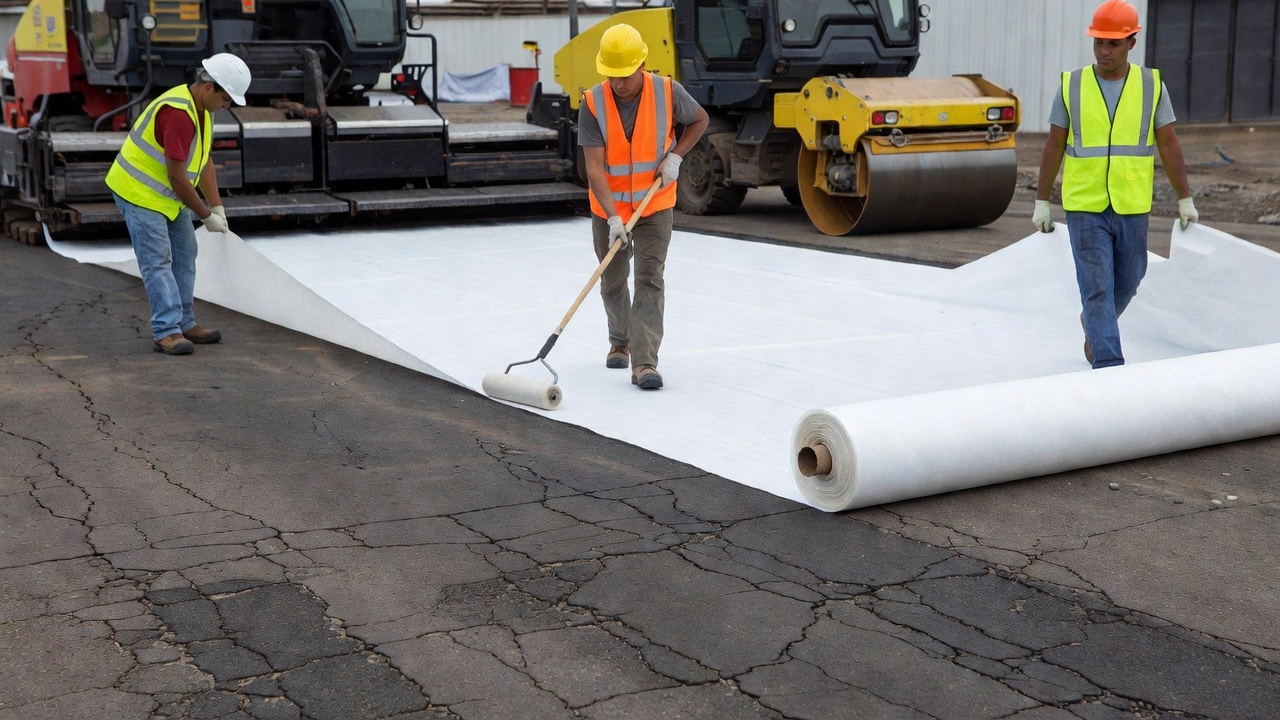
4.2 Geosynthetic Interlayers
Geosynthetic interlayers — including geotextiles (nonwoven needle-punched fabrics), geogrids (open-grid polymer or glass fiber structures), and paving grids — are placed at the interface between the existing pavement and the new overlay, typically bonded with a tack coat of asphalt emulsion or polymer-modified binder. Unlike SAMIs, which absorb stress through bulk deformation, geosynthetic interlayers function primarily through reinforcement: they bridge the existing crack and redistribute tensile stresses horizontally, converting the vertical crack-driving stress into in-plane tension that the geosynthetic resists.
Glass fiber paving grids, such as the GlasGrid system distributed by Tensar International, are manufactured from high-tensile-strength glass fibers coated with a polymer-modified bitumen for compatibility with asphalt. With tensile strengths typically exceeding 100 kN/m in both longitudinal and transverse directions and elongation at break of less than 4 percent, these grids provide substantial reinforcement at low strain levels. The grid structure — with aperture sizes of 12.5 to 25 mm — allows the asphalt overlay to bond through the grid openings to the underlying pavement, maintaining interlayer shear strength. Tensar reports that glass fiber grid systems can extend pavement service life by 200 percent or more when properly installed between a leveling course and the surface course.
Nonwoven geotextiles function differently: when saturated with asphalt tack coat, they form a waterproofing membrane that prevents surface water from penetrating through reflected cracks to the underlying layers, thereby reducing moisture-accelerated damage even after cracks have reflected. Polypropylene and polyester geotextiles with mass per unit area of 135 to 200 g/m² are commonly specified. The saturation and bonding of the geotextile require careful construction quality control — insufficient tack coat leads to delamination, while excessive tack coat can cause slippage of the overlay.
Finite element analyses by Joseph (1989) using crack band theory demonstrated that geosynthetic reinforcement at the overlay interface reduces the stress at the crack tip by approximately 15 to 20 percent. While this may appear modest, the non-linear relationship between stress amplitude and fatigue life means that even small stress reductions can produce substantial life extensions. The same analysis showed that reinforcement becomes increasingly effective as the crack propagates, suggesting that geosynthetics are particularly valuable for retarding the later stages of crack growth rather than preventing initiation.
4.3 Composite Interlayer Systems
The most advanced interlayer approach combines SAMI and geosynthetic technologies into a composite stress-relieving interlayer. In this configuration, a SAMI layer is placed first to provide stress absorption and waterproofing, and a geogrid is embedded within or placed atop the SAMI to provide tensile reinforcement. Research by Cheetham and Haas demonstrated that composite interlayers can achieve stress reductions equivalent to a significantly thicker overlay — a 30 mm SAMI with geogrid reinforcement providing similar crack mitigation to a 50 mm SAMI alone. This has important practical implications where overlay thickness is constrained by vertical clearances, approach surface requirements, or weight considerations on bridge decks.
4.4 Increased Overlay Thickness
Increasing overlay thickness reduces the stress intensity at the crack tip by increasing the distance between the crack and the overlay surface and by distributing wheel loads over a larger area at the crack plane. The relationship, however, follows a law of diminishing returns. The empirical observation that one inch of asphalt provides approximately one year of crack resistance means that even a 150 mm (6-inch) overlay — which would be unusually thick for most rehabilitation projects — provides only about six years of crack-free performance without additional mitigation measures.
The AASHTO 1993 pavement design guide provided minimum overlay thickness recommendations based on existing pavement condition: 50 mm (2 inches) for pavements in good condition with minimal cracking, 75 to 100 mm (3 to 4 inches) for pavements with moderate cracking, and 125 mm (5 inches) or more for severely cracked pavements. These values were recognized as minimums that would require supplementary mitigation for satisfactory long-term performance. Modern mechanistic-empirical design procedures explicitly model the relationship between overlay thickness and reflective cracking propagation rate, allowing engineers to optimize thickness against cost and performance requirements.
4.5 Crack-and-Seat and Rubblization
Rather than attempting to prevent crack reflection through the overlay, crack-and-seat and rubblization techniques eliminate the crack-driving mechanism by destroying the structural continuity of the underlying concrete pavement before overlay placement.
Crack-and-seat involves breaking the existing concrete pavement into pieces typically 0.3 to 0.6 m (1 to 2 ft) in size using a pavement breaker, guillotine hammer, or resonant frequency breaker. The broken pieces are then seated into the subgrade with a heavy pneumatic or vibratory roller, creating a fragment layer that functions as a high-quality granular base rather than a slab. The key to successful crack-and-seat is achieving sufficiently small fragment sizes to eliminate slab action — and therefore thermal movement — while maintaining adequate structural contribution. Fragment sizes larger than 0.6 m may still exhibit some slab behavior and thermal movement, risking reflective cracking in the overlay.
Rubblization is a more aggressive version that reduces the concrete pavement to fragments typically 50 to 150 mm (2 to 6 inches) in size, essentially converting it to a granular base material. Rubblization is typically performed with resonant frequency breakers, multi-head breakers, or guillotine hammers, followed by compaction with vibratory rollers. The resulting rubblized layer has an elastic modulus of approximately 200 to 700 MPa — comparable to a high-quality crushed stone base — and exhibits no slab action.
Both techniques require that the existing concrete be unreinforced, or that any reinforcement be adequately severed. The thickness of the asphalt overlay placed over crack-and-seat or rubblized concrete is typically 100 to 200 mm (4 to 8 inches) for highway applications and 150 to 250 mm (6 to 10 inches) for airport applications, designed using conventional flexible pavement methods since the underlying layer no longer behaves as a rigid pavement.
5. Severity Measurement and Classification
The measurement and classification of reflective cracking severity follows standardized protocols that enable consistent condition assessment across different pavements, agencies, and inspection programs. The most widely used standard is ASTM D6433 — Standard Practice for Roads and Parking Lots Pavement Condition Index Surveys, with its airport counterpart ASTM D5340 — Standard Test Method for Airport Pavement Condition Index Surveys. These standards define reflective cracking as a distinct distress type with three severity levels based on crack width, spalling, and associated distresses.
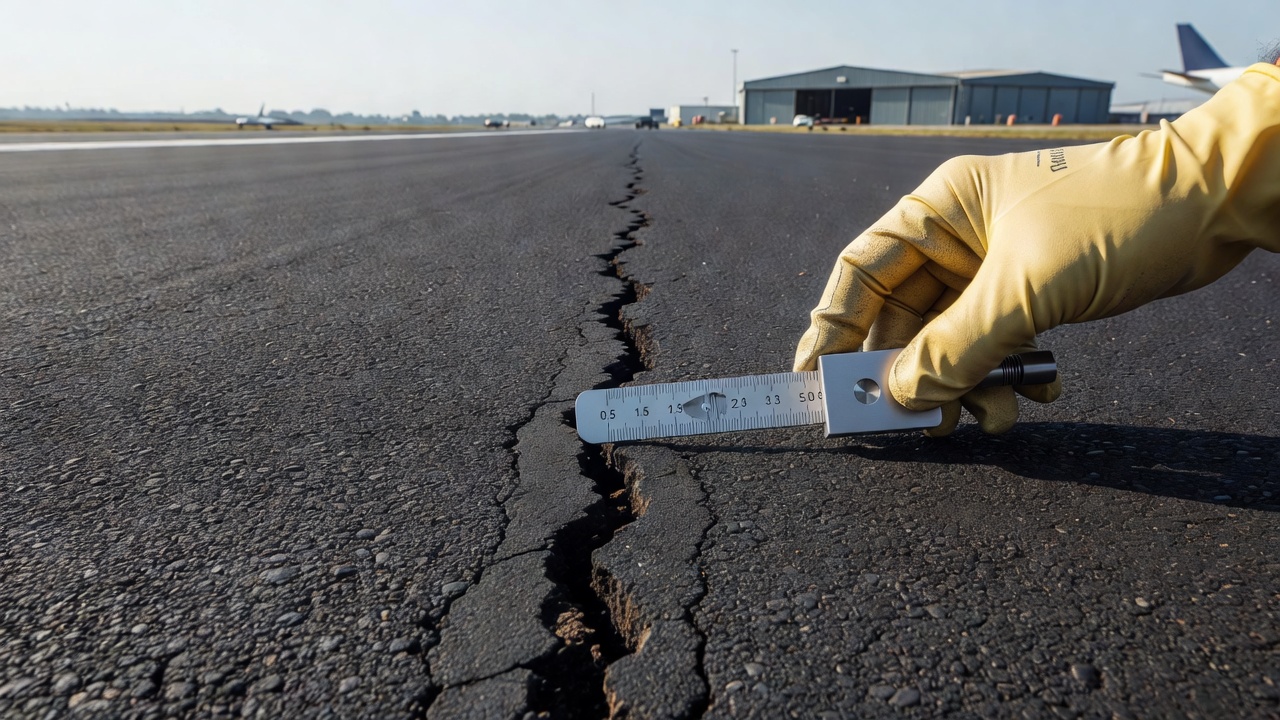
Low severity reflective cracking is characterized by crack widths less than 6 mm (0.25 inch), with no spalling along the crack edges, no pumping of water or fines through the crack, and no evidence of raveling or secondary cracking adjacent to the primary crack. At this severity level, the crack is primarily a cosmetic concern and a potential pathway for water infiltration, but it does not yet significantly affect ride quality or structural integrity.
Medium severity reflective cracking exhibits crack widths between 6 and 19 mm (0.25 to 0.75 inch), with minor spalling — small fragments of asphalt breaking away from the crack edges — and possible pumping. Pumping, the ejection of water and fine material through the crack under traffic loading, indicates that the crack has penetrated the full depth of the overlay and that water is moving through the pavement structure, accelerating damage to the subgrade and base layers.
High severity reflective cracking has crack widths greater than 19 mm (0.75 inch), severe spalling with significant material loss along the crack, definite pumping, and often raveling or secondary cracking in the vicinity of the primary crack. At this severity, the crack represents a structural defect that compromises load transfer, allows substantial water infiltration, and may pose a Foreign Object Debris (FOD) hazard in airport applications.
The measurement of crack density for PCI calculation is expressed in linear meters or feet of cracking per pavement sample unit (typically 225 m² or 2,500 ft² for roads, and 450 m² or 5,000 ft² for airports). Deduct values are assigned based on the density and severity, with higher deducts for higher severities at any given density. The cumulative deduct values are used to calculate the Pavement Condition Index on a 0–100 scale, where 100 represents a pavement in perfect condition.
In addition to the ASTM PCI methodology, many agencies supplement crack measurements with Falling Weight Deflectometer (FWD) testing to assess load transfer efficiency across reflected cracks, Ground Penetrating Radar (GPR) to detect subsurface cracking before it becomes visible at the surface, and coring to verify the depth of crack penetration and the condition of the underlying layers.
6. Reflective Cracking in Airport Pavement Overlays
Airport pavements present unique challenges for reflective cracking management due to the extreme loading conditions, stringent safety requirements, and operational constraints that characterize the aviation environment. Aircraft landing gear impose concentrated loads that can exceed 30 tonnes per wheel on small tire contact areas, producing pavement stresses far greater than those generated by highway vehicles. The Federal Aviation Administration (FAA) and the International Civil Aviation Organization (ICAO) provide specific guidance for airport pavement overlay design, though reflective cracking remains an area where engineering judgment and supplementary analysis are required.
The FAA Advisory Circular 150/5320-6 — Airport Pavement Design and Evaluation provides the primary design framework for airport pavements in the United States. The FAA’s FAARFIELD (FAA Rigid and Flexible Iterative Elastic Layered Design) software, used for thickness design of airport pavements, computes the structural life of flexible and rigid pavements based on layered elastic analysis and cumulative damage factors. However, FAARFIELD does not explicitly model reflective cracking, delamination, or other overlay-specific deterioration mechanisms. As noted in ICAO’s 2024 Workshop on Aerodrome Pavement, this gap means that the computed structural life from FAARFIELD may overestimate overlay performance if reflective cracking is not separately addressed through mitigation strategies.
Airport pavement overlays on concrete typically range from 100 to 250 mm (4 to 10 inches) in thickness, with the thicker end of the range used for heavy aircraft such as the Boeing 777, Airbus A380, or military cargo aircraft. The standard concrete slab dimensions for airport pavements — typically 6.25 m × 6.25 m (20 ft × 20 ft) for FAA-designed pavements and up to 7.6 m × 7.6 m (25 ft × 25 ft) for some ICAO designs — produce joint spacings that are roughly twice those of highway pavements, resulting in larger joint movements under thermal cycling and correspondingly higher stress concentrations in the overlay.
The FAA’s Airport Asphalt Pavement Technology Program (AAPTP) Project 05-04 specifically investigated techniques for mitigation of reflective cracks in airside pavements. The study evaluated stress-absorbing membrane interlayers, geosynthetic interlayers, rubblization, and crack-and-seat techniques under aircraft loading conditions. Key findings included: SAMIs with polymer-modified asphalt rubber binders showed superior performance for runways and high-speed taxiways; geogrid interlayers were most effective when placed at a depth of 50 to 75 mm below the overlay surface (i.e., between a leveling course and surface course rather than directly on the concrete); and rubblization followed by a 200 to 250 mm asphalt overlay provided a long-term solution comparable to full reconstruction for severely deteriorated concrete aprons.
Operational considerations strongly influence airport rehabilitation decisions. Runway closures for overlay construction are typically limited to overnight windows of 6 to 8 hours, making full-depth reconstruction impractical for major runways. This constraint favors overlay solutions with interlayer treatments that can be placed and overlaid within a single shift. The Arizona State University pavement research program has developed a reflective cracking model specifically for airport asphalt overlay design, incorporating the effects of aircraft gear configuration (single, dual, dual-tandem, and tridem), tire pressure, and the thermal environment of different climate regions.
The table below summarizes typical airport overlay designs with reflective cracking mitigation:
Aircraft Type
PCC Condition
Overlay Thickness
Recommended Mitigation
Heavy (B777, A340)
Good, good LTE
125–175 mm
SAMI + geogrid composite interlayer
Heavy (B777, A340)
Fair, moderate LTE
175–225 mm
Crack-and-seat + SAMI
Heavy (B777, A340)
Poor, low LTE
225–275 mm
Rubblization or reconstruct
Medium (B737, A320)
Good, good LTE
100–150 mm
Geotextile or geogrid interlayer
Medium (B737, A320)
Fair to poor
150–200 mm
SAMI or crack-and-seat
General Aviation
Any
75–125 mm
Geotextile interlayer or increased thickness
7. Detection by Artificial Intelligence
The detection and classification of reflective cracking has historically relied on manual visual surveys — a labor-intensive, subjective, and potentially hazardous process requiring inspectors to walk or drive pavements while recording distress data. The application of artificial intelligence (AI) and computer vision to pavement condition assessment is transforming this process, enabling faster, more consistent, and more detailed crack detection than manual methods.
Modern AI-based pavement inspection systems use high-resolution cameras mounted on vehicles or drones to capture continuous imagery of the pavement surface. These images — typically collected at resolutions of 1 to 2 mm per pixel at highway speeds — are processed through deep convolutional neural networks (CNNs) trained on large datasets of labeled pavement distress images. The neural networks learn to identify cracks, classify them by type (reflective, fatigue, block, longitudinal, transverse, etc.), measure their width and extent, and assign severity ratings in accordance with ASTM D6433 or equivalent standards.
The specific challenge for reflective cracking detection is distinguishing it from other crack types that may appear similar at the surface. Reflective cracks are typically straighter and more regular than fatigue cracks, occur at spacings that correspond to underlying joint or crack patterns, and may extend across the full width of the pavement lane or runway. Advanced AI systems incorporate not only local pixel-level crack detection but also spatial pattern analysis that recognizes the characteristic regularity of reflective cracking. Some systems integrate historical pavement data — such as known joint spacings in the underlying concrete — as prior information to improve classification accuracy.
Benesch, an engineering consulting firm, developed an AI-based pavement inspection workflow that has been recognized by Bentley Systems for reducing inspection time by 75 percent compared to manual methods. The system uses machine learning models trained on thousands of pavement images to detect and classify cracks including reflective cracking, feeding the results directly into pavement management systems and asset management databases. Similar systems have been deployed by state departments of transportation and airport authorities, with reported crack detection accuracies exceeding 90 percent for cracks wider than 2 mm.
The integration of AI crack detection with drone-based imagery collection is particularly relevant for airport applications, where access to runways and taxiways for manual inspection is heavily restricted. Drones equipped with high-resolution cameras can survey an entire runway in a single flight during a brief closure window, with AI processing of the imagery completed within hours. This capability enables more frequent condition monitoring, earlier detection of emerging reflective cracking, and more timely intervention — all of which contribute to extended pavement life and reduced lifecycle costs.
The National Academies’ 2024 report on AI Applications for Automatic Pavement Condition Evaluation identified several emerging capabilities: the integration of multiple imaging modalities (visible light, infrared thermography, and ground-penetrating radar) for subsurface crack detection before surface manifestation; the use of change detection algorithms that compare sequential surveys to identify new or propagating cracks; and the development of predictive models that forecast crack growth based on observed propagation rates and projected traffic and climate data.
8. Rehabilitation Alternatives for Reflective-Cracked Pavements
When reflective cracking has already developed to a severity that compromises pavement performance or safety, rehabilitation is required. The selection of an appropriate rehabilitation strategy depends on the current condition of the overlay and the underlying pavement, the crack severity and extent, the available construction windows, and the remaining design life expectations for the pavement.
Crack sealing and filling is the least intensive intervention, suitable for low-severity reflective cracking where the primary concern is preventing water infiltration. Cracks are cleaned with compressed air and routed to create a uniform reservoir, then filled with hot-applied rubberized asphalt sealant or cold-applied polymer-modified emulsion. Crack sealing does not restore structural capacity or address the underlying crack propagation mechanism, and sealed cracks will typically continue to reflect through subsequent overlays unless additional measures are taken. Typical service life for crack sealing in reflective cracking applications is 2 to 4 years.
Milling and inlay involves removing the cracked asphalt overlay to a specified depth — typically 50 to 100 mm — and replacing it with new asphalt. This treatment addresses surface distress but does not eliminate the underlying discontinuity, and reflective cracking will recur unless the milling depth reaches below the crack tips or an interlayer is placed on the exposed surface before the inlay. Milling that penetrates 25 mm into the underlying concrete or stabilized base can remove existing crack tips and delay but not prevent crack re-initiation.
Mill and overlay with interlayer combines partial-depth milling (typically 50 to 75 mm) of the cracked surface with the placement of a SAMI or geosynthetic interlayer on the milled surface, followed by a new asphalt overlay. This approach removes surface distress while providing a stress-attenuating layer to address the crack propagation mechanism. It represents the most common rehabilitation strategy for moderately reflective-cracked pavements and can provide 10 to 15 years of service life with proper design and construction.
Cold in-place recycling (CIR) pulverizes the existing asphalt overlay in place, mixes it with asphalt emulsion or foamed bitumen, and repaves it as a new base layer, which is then covered with a surface course. CIR eliminates the existing crack pattern and creates a homogeneous layer that does not contain stress-concentrating discontinuities. The recycled layer’s modulus is typically lower than that of new hot-mix asphalt, which can be advantageous for stress attenuation. CIR depths of 75 to 125 mm are typical, and the process can be completed within a single working day, making it suitable for pavements with limited closure windows.
Full-depth reclamation (FDR) extends the recycling process through the full asphalt thickness and into the underlying base or subgrade, creating a new stabilized base layer. FDR eliminates all existing cracks and joints and provides the most thorough rehabilitation short of full reconstruction. The stabilized base can incorporate cement, lime, asphalt emulsion, or foamed bitumen as the stabilizing agent, with cement stabilization providing higher strength but potentially introducing new shrinkage cracks that could themselves become sources of reflective cracking in future overlays.
Hot in-place recycling (HIR) heats and scarifies the existing asphalt surface, mixes it with rejuvenating agents and sometimes virgin material, and repaves it in place. HIR typically treats the upper 25 to 50 mm of the pavement and does not reach the depth of most reflective cracks, making it suitable only for pavements where reflective cracking is very shallow or where HIR is combined with deeper treatments.
Overlay with rubblization of the underlying concrete, discussed in Section 4, represents the most comprehensive rehabilitation approach for composite pavements with extensive reflective cracking. By destroying the slab action of the concrete, it eliminates the driving mechanism for crack reflection and provides a uniform, crack-free base for the new asphalt overlay. This approach effectively converts the rehabilitation from an overlay of a rigid pavement to a new flexible pavement design.
The selection among these alternatives requires a thorough pavement evaluation including visual condition surveys, FWD deflection testing to assess structural capacity and load transfer, coring to determine layer thicknesses and conditions, and drainage assessment. Life-cycle cost analysis, incorporating initial construction costs, anticipated maintenance interventions, and the value of reduced operational disruption, provides the economic framework for comparing alternatives over a 20 to 30 year analysis period.
Frequently Asked Questions
Reflective cracking is caused by stress concentrations at the tip of existing cracks or joints in the underlying pavement. These stresses arise from three primary mechanisms: (1) traffic-induced bending that creates maximum tensile stress at the bottom of the overlay directly above the discontinuity, (2) traffic-induced shear from differential vertical deflections across the crack when load transfer is poor, and (3) thermally induced tension from horizontal contraction and expansion of the underlying layer during temperature cycles. The crack propagates upward through the overlay as these stresses exceed the fracture resistance of the asphalt mixture.
Several mitigation strategies exist: Stress-Absorbing Membrane Interlayers (SAMIs) made of rubberized asphalt that absorb differential movements; geosynthetic interlayers (geotextiles, geogrids, paving grids) that dissipate crack-tip stresses horizontally; increased overlay thickness (though the empirical rule of roughly one year of crack resistance per inch of thickness makes this a limited solution); crack-and-seat or rubblization of the underlying concrete to eliminate slab action before overlay; and the use of polymer-modified binders in the asphalt mix to enhance fracture resistance.
Joint reflection cracking occurs when the joints in an underlying jointed Portland cement concrete (JPCC) pavement propagate through the asphalt overlay. These cracks are typically straight, regularly spaced (matching the concrete slab dimensions), and uniform in width. Crack reflection cracking propagates from random or fatigue cracks in deteriorated asphalt or continuously reinforced concrete. These cracks tend to be more irregular in pattern, spacing, and width. Both types follow the same mechanistic principles of stress concentration and crack propagation.
Per ASTM D6433 (PCI method) and ASTM D5340 (airport PCI), reflective cracking severity is classified as Low (crack width less than 6 mm, no spalling, no pumping), Medium (crack width 6–19 mm, minor spalling, possible pumping), or High (crack width greater than 19 mm, severe spalling, definite pumping or raveling). Measurement uses crack width gauges, with density expressed as linear feet or meters of cracking per pavement section. Automated methods using AI-based image analysis are increasingly used for consistent classification.
Airport pavements face more severe reflective cracking challenges due to heavier concentrated aircraft loads (often exceeding 500,000 lbs on small tire contact areas), wider concrete slab dimensions (typically 6.25 m or 20 ft square), and limited closure windows that constrain rehabilitation options. FAA Advisory Circular 150/5320-6 and ICAO Doc 9157 Part 3 provide specific guidance for airport overlay design. FAA's FAARFIELD software does not directly model reflective cracking, requiring engineers to apply separate mitigation strategies such as stress-absorbing interlayers, rubblization, or geosynthetic reinforcement to address this distress mode.
Protect Your Pavement Overlays from Reflective Cracking
Learn how advanced interlayer systems, optimized overlay designs, and AI-powered inspection can extend the service life of your asphalt overlays and reduce lifecycle costs for runways, taxiways, and road pavements.
Alligator cracking — also called fatigue cracking — is an interconnected crack pattern resembling alligator skin that indicates structural failure of the asphal...
Longitudinal Cracking in Asphalt and Concrete Pavements
Longitudinal cracks run parallel to the pavement centerline or direction of travel. Causes include poor construction joint bonding, reflective cracking from und...
Transverse Cracking in Asphalt and Concrete Pavements
Transverse cracks run perpendicular to the pavement centerline, most commonly caused by thermal contraction at low temperatures or reflective cracking from unde...
26 min read
Pavement defects
Asphalt cracking
+3
Cookie Consent We use cookies to enhance your browsing experience and analyze our traffic. See our privacy policy.