Pavement rehabilitation encompasses major structural improvements to extend pavement service life beyond routine maintenance. It includes overlays, milling and inlay, in-place recycling, whitetopping, and partial reconstruction. Covers rehabilitation triggers (PCI; IRI; structural capacity), treatment selection logic, lifecycle cost analysis, and airport pavement rehabilitation constraints (limited possession times, nighttime work).
Definition and Distinction from Maintenance and Reconstruction
Pavement rehabilitation is a structural restoration strategy applied to existing pavements that have deteriorated beyond the point where routine or preventive maintenance can effectively preserve performance. Rehabilitation involves engineered modifications that increase or restore the structural capacity of the pavement, as opposed to maintenance which only preserves the existing structure. Under FAA Advisory Circular 150/5320-6G (Airport Pavement Design and Evaluation, Chapter 4), pavement rehabilitation is formally defined as work undertaken to extend the service life of an existing pavement by adding structural value, correcting major surface distresses, or improving functional characteristics. ICAO Annex 14, Volume I (Aerodrome Design and Operations) requires that the surface of runways, taxiways, and aprons be maintained in a condition that does not impair the safety of aircraft operations — and rehabilitation is the primary mechanism by which this condition is restored once preventive maintenance is no longer adequate.
The fundamental distinction between maintenance, rehabilitation, and reconstruction is defined by the type and depth of pavement intervention. Preventive maintenance consists of surface treatments applied to pavements in good condition (PCI 70-100) to slow the rate of deterioration. Examples include crack sealing, chip sealing, slurry sealing, and fog sealing. These treatments cost $1-5 per square yard and extend service life by 3-7 years without adding structural capacity. Routine maintenance addresses localized defects such as pothole patching, joint sealing, and minor spall repair — applied to pavements in fair to good condition (PCI 55-85). These are reactive rather than proactive treatments costing $5-20 per square yard.
Rehabilitation involves structural interventions applied to pavements in fair to poor condition (PCI 40-70). Rehabilitation treatments cost $15-60 per square yard and extend service life by 10-20+ years. These treatments add measurable structural thickness or strength to the pavement system. Examples include hot-mix asphalt (HMA) overlay (2-6 inches), mill and inlay (2-4 inch removal and replacement), cold in-place recycling (3-6 inch depth), and whitetopping (6-10 inch concrete overlay). Reconstruction is complete removal and replacement of all pavement layers, including subgrade improvement if necessary. Reconstruction costs $40-120 per square yard and provides a new 20-year design life. It is only warranted when the existing pavement structure is beyond rehabilitation — typically PCI below 25-40 or when subgrade failure exists.
The decision boundary between maintenance, rehabilitation, and reconstruction is not arbitrary. It is determined through systematic pavement condition evaluation per ASTM D5340 (Standard Test Method for Airport Pavement Condition Index Surveys), structural evaluation per FAA AC 150/5320-6G Chapter 5, and lifecycle cost analysis per FAA Order 5100.38C. The airport pavement management system (APMS) uses condition data to identify the optimal timing for each intervention based on the pavement deterioration curve — a characteristic S-shaped function where the rate of deterioration accelerates once PCI drops below approximately 60-70. Rehabilitating before the deterioration rate accelerates maximizes cost-effectiveness.
Rehabilitation Triggers
Pavement Condition Index (PCI) Thresholds
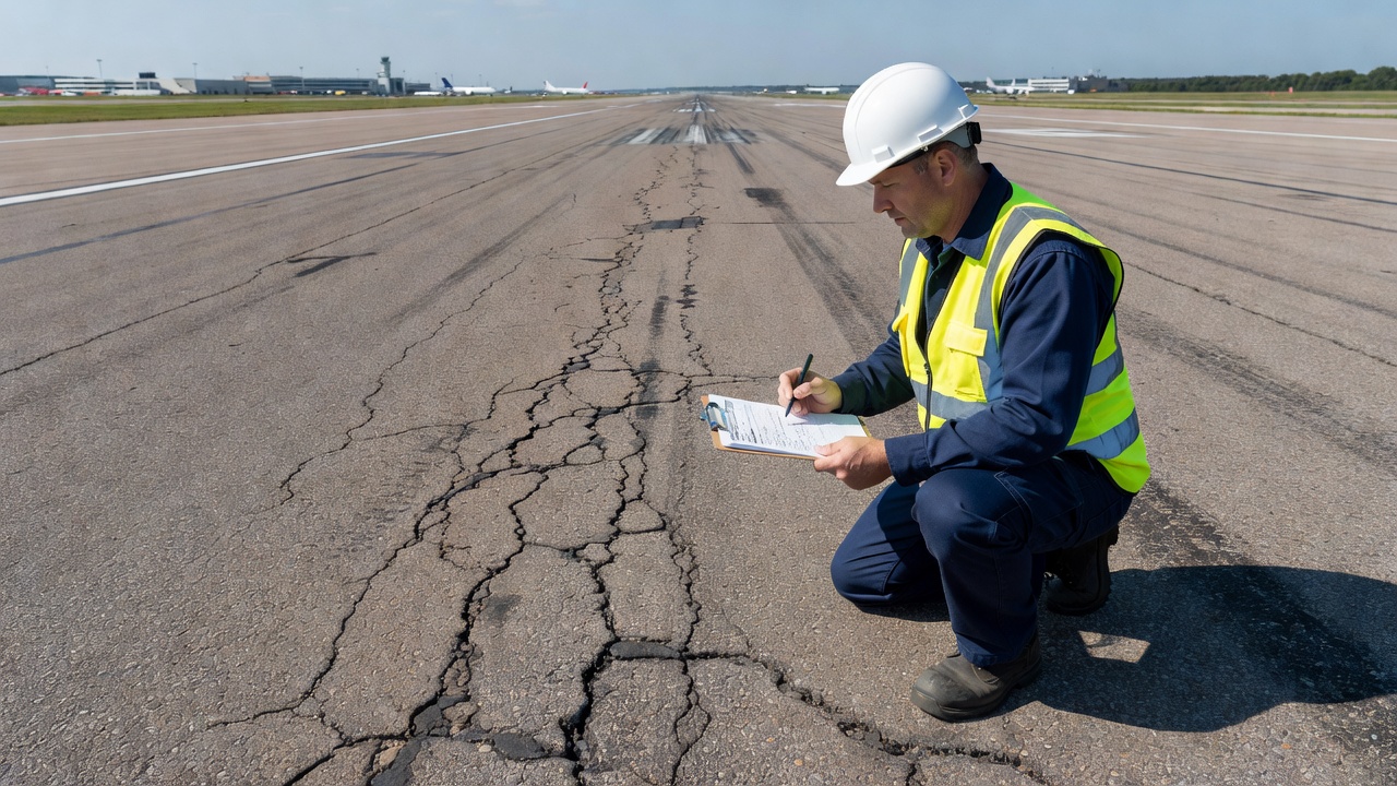
The Pavement Condition Index (PCI) is the primary condition-based trigger for airport pavement rehabilitation worldwide. Per ASTM D5340 and FAA AC 150/5380-7B (Airport Pavement Management Program), PCI is a numerical rating from 0 (failed) to 100 (excellent) derived from a visual survey of pavement distress type, severity, and density. The PCI procedure classifies 19 distress types for asphalt-surfaced pavements (including alligator cracking, block cracking, rutting, weathering, and raveling) and 15 distress types for concrete pavements (including corner break, divided slab, joint spalling, and faulting).
The industry-standard PCI thresholds for rehabilitation decision-making are:
PCI Range
Condition Rating
Recommended Action
Typical Treatment
86-100
Excellent
Preventive maintenance
Crack sealing, fog seal
71-85
Very Good
Preventive maintenance
Slurry seal, chip seal
56-70
Good
Minor rehabilitation
Surface recycling, thin overlay, mill & inlay
41-55
Fair
Major rehabilitation
Structural overlay, CIR, whitetopping
26-40
Poor
Major rehabilitation / Reconstruction
Thick overlay, FDR, reconstruction
11-25
Very Poor
Reconstruction
Full reconstruction
0-10
Failed
Reconstruction
Emergency reconstruction
Most airport pavement management systems use a PCI threshold of 55-60 as the trigger for initiating rehabilitation planning. At PCI 55, the pavement has typically entered the accelerated deterioration phase of the life-cycle curve where the rate of condition loss increases dramatically. The FAA-recommended PCI threshold for mandatory rehabilitation action in AIP-funded projects is PCI 55 in the primary structural area and PCI 40 in secondary areas. The FAA PAVEAIR system, used by airports to report pavement condition data, categorizes pavements with PCI below 55 as requiring rehabilitation within 1-3 years.
International Roughness Index (IRI) Thresholds
The International Roughness Index (IRI) is a functional performance indicator that measures pavement surface profile unevenness. IRI is calculated from the longitudinal pavement profile measured using a laser inertial profiler (per ASTM E950) and expressed in inches per mile (in/mi) or meters per kilometer (m/km). Unlike PCI which measures visible distress, IRI directly measures the ride quality experienced by aircraft during takeoff, landing, and taxiing operations.
For airport pavements, IRI thresholds are specified in FAA AC 150/5380-7B (Appendix B, Table B-2) and ICAO Annex 14 Attachment A Section 5:
New construction / Excellent condition: IRI < 60 in/mi (1.0 m/km). Surface is smooth, no ride quality issues.
Good condition, routine maintenance: IRI 60-100 in/mi (1.0-1.6 m/km). Minor surface irregularities tolerable for all operations.
Fair condition, rehabilitation consideration: IRI 100-140 in/mi (1.6-2.2 m/km). Noticeable roughness. Rehabilitation should be evaluated.
Poor condition, rehabilitation required: IRI 140-180 in/mi (2.2-2.8 m/km). Roughness may cause aircraft vibration. Rehabilitation planning should be initiated.
Very poor, mandatory rehabilitation: IRI > 180 in/mi (2.8 m/km). Roughness may impair aircraft control. Rehabilitation is mandatory.
The relationship between IRI and PCI is not directly correlated — a pavement can have a high PCI (few visible cracks) but high IRI (surface settlement or faulting), or vice versa. Therefore, both PCI and IRI must be evaluated independently to determine rehabilitation needs. The FAA Airport Pavement Management Program requires both condition data types to produce the Pavement Condition Rating (PCR) composite index used in PAVEAIR.
Structural Capacity Triggers
Structural capacity assessment determines whether the existing pavement has adequate strength to support current and projected aircraft traffic. This is evaluated using nondestructive testing (NDT) with the Falling Weight Deflectometer (FWD) per ASTM D4694 and FAA AC 150/5320-6G Appendix C. The FWD applies a transient impulse load of 12,000 to 60,000 pounds (53-267 kN) — simulating the dynamic loading of an aircraft landing gear — and measures the resulting deflection basin using geophones spaced at 0, 8, 12, 18, 24, 36, and 60 inches from the load center.
Structural deficiency triggers for rehabilitation include:
Layer modulus below design minimum: Backcalculated asphalt modulus < 200,000 psi, base modulus < 20,000 psi, or subgrade modulus < 5,000 psi indicates material deterioration or moisture damage requiring rehabilitation.
Excessive surface deflection: Center deflection > 0.020 inches (0.5 mm) under standard FWD load for flexible pavements indicates structural weakness requiring overlay.
Load transfer efficiency < 70% at joints: For rigid pavements, FWD-measured LTE below 70% indicates joint deterioration requiring slab replacement, dowel bar retrofitting, or unbonded concrete overlay.
Cumulative Damage Factor (CDF) > 1.0: Per FAARFIELD structural analysis, a CDF greater than 1.0 indicates the pavement has exceeded its design life and structural rehabilitation is needed.
Structural deficiency identified by FAARFIELD evaluation: FAA AC 150/5320-6G Chapter 5 provides procedures for evaluating existing pavement structural adequacy using FAARFIELD. When the analysis shows the existing pavement thickness is inadequate for projected traffic, an overlay is required.
The relationship between condition-based (PCI) and structural triggers is critical: a pavement may have acceptable PCI (e.g., 65 with mostly cosmetic cracking) but inadequate structural capacity for increasing aircraft loads — requiring structural overlay even though condition appears acceptable. Conversely, a pavement with low PCI but adequate structural capacity may only require functional restoration (mill and overlay) rather than structural reinforcement.
Treatment Options Matrix
The selection of rehabilitation treatment depends on pavement type (flexible asphalt or rigid concrete), failure mechanism (structural deficiency, functional deficiency, or material deterioration), existing layer thicknesses, available budget, and operational constraints. The major treatment options are as follows.
Asphalt Overlay
The hot-mix asphalt (HMA) overlay is the most common pavement rehabilitation treatment worldwide. It consists of placing one or more layers of HMA over the existing pavement surface. For airport applications per FAA AC 150/5320-6G and FAARFIELD design procedures, overlay thickness is structurally designed based on existing pavement condition and projected traffic. Minimum overlay thickness for structural purposes is 3 inches (75 mm) for runways. For non-structural surface restoration (functional-only), minimum overlay thickness is 1.5 inches (38 mm).
The HMA overlay design in FAARFIELD uses the effective thickness method where the existing pavement structure is assigned an effective structural value based on condition (typically 50-80% of its original capacity for pavements in fair condition). The required overlay thickness is the difference between the thickness required for new design traffic and the effective thickness of the existing pavement. Surface preparation per FAA AC 150/5320-6G Section 4.10 requires alligatored areas to be patched, cracks wider than 3 mm sealed, a tack coat applied at 0.05-0.15 gal/sy, and any grade adjustments made through variable-depth milling.
Advantages include relatively fast construction, well-understood performance, and ability to restore both structural capacity and ride quality. Limitations include reduced clearance at overhead structures (signage gantries, bridges), reduced shoulder elevation differential, and need for grade adjustments at pavement-light interfaces and drainage inlets.
Milling and Inlay
Milling and inlay — also called mill and fill or mill and overlay — involves removing (milling) a specified depth of the existing asphalt surface, typically 2 to 4 inches (50-100 mm), and replacing it with new HMA. This treatment is used when the pavement has adequate structural capacity at depth but surface-layer distress (rutting, raveling, thermal cracking, or oxidation) has reached the point where overlay alone would be problematic due to grade constraints.
Cold milling is performed using a rotary cutting drum with carbide-tipped teeth that plane off the specified depth. The milled material is loaded into trucks and removed for recycling — either reprocessed into new HMA (RAP — Reclaimed Asphalt Pavement) or used as granular base material. Milling restores pavement profile, cross-slope, and texture; removes surface contamination and oxidized binder; and provides a clean, textured surface that ensures mechanical interlock with the new overlay. The milled surface is swept and cleaned, a tack coat is applied, and the HMA inlay is placed and compacted to the specified grade.
Milling depth is determined by: depth of surface distress (minimum 1.5 inches to remove all cracking); minimum lift thickness for compaction (typically 2 times nominal maximum aggregate size); and grade-control requirements (milling to match existing cross-slope or correct drainage deficiencies). Milling can be variable-depth to restore crown and cross-slope.
Hot In-Place Recycling (HIR)
Hot in-place recycling (HIR) is a specialized rehabilitation process that heats and softens the existing asphalt pavement surface to a depth of 0.75 to 2 inches (20-50 mm), scarifies or mills the softened material, mixes it with a rejuvenating agent (typically a soft asphalt emulsion or specialized rejuvenator that restores the aged binder properties), and places and compacts the recycled material in a single continuous train operation. The treatment is performed by a purpose-built HIR train consisting of pre-heaters, a heater-scarifier, mixing chamber (where rejuvenator is added), a laydown machine, and rollers.
HIR addresses surface-layer distress: oxidation, raveling, surface cracking up to approximately 0.25 inch wide, and minor rutting up to 0.5 inch depth. Per FHWA-HIF-14-008 and ACRP Report 22 (Table B-1, Catalog of Airport Pavement Preservation Treatments), HIR is applicable for pavements with PCI 50-70 exhibiting surface-condition deficiencies with structurally sound underlying layers. HIR is not suitable for pavements with deep structural cracking, alligator cracking in wheel paths, subgrade failure, or insufficient base thickness.
The environmental benefits of HIR are significant: 100% reuse of existing materials, elimination of trucking for material removal and import, 30-40% reduction in greenhouse gas emissions compared to mill-and-overlay, and up to 50% reduction in virgin binder consumption. Construction speed is high — an HIR train can process 10-15 feet per minute, rehabilitating a typical runway width in two passes per night.
Cold In-Place Recycling (CIR)
Cold in-place recycling (CIR) is a rehabilitation process that mills 3 to 6 inches (75-150 mm) of the existing asphalt pavement, processes the milled material through a crushing and screening unit, mixes it with a stabilizing agent (foamed asphalt or asphalt emulsion), and places the recycled material as a new stabilized base layer. Unlike HIR, CIR operates at ambient temperature — no heating is required. The CIR material is typically paved to the same cross-section and compacted, then covered with a new HMA surface course (minimum 1.5-2 inches) within days.
CIR is applicable for pavements with moderate structural distress (alligator cracking, block cracking up to moderate severity) and PCI 40-60. The treatment is deeper than HIR, addressing not just surface condition but also upper-base structural issues. Per FAA AC 150/5320-6G Section 4.9, CIR is recognized as an alternative to conventional reconstruction for flexible pavements with significant structural deterioration but adequate subgrade support.
The foamed asphalt stabilization process injects a small amount of cold water (2-3% by weight of asphalt) into hot asphalt binder (170-190°C), causing the binder to foam and expand to 15-20 times its original volume. The foamed binder coats the reclaimed aggregate particles, providing a semi-flexible, water-resistant base material with stiffness comparable to or exceeding conventional granular base. Cement or lime (1-2%) is often added as an active filler to improve moisture resistance and early strength. For asphalt emulsion CIR, the emulsion (typically CMS-2 or SS-1 grade) is mixed at 2-4% by weight of RAP material.
The FAA Airport Technology Branch has conducted extensive research on CIR for airfield pavements through the ACRP Project 21-506 (Expanding In-Place Cold Recycling for Flexible Airfield Pavement), demonstrating that properly designed and constructed CIR base layers can achieve structural coefficients equivalent to HMA base layers (a1 = 0.35-0.40 per AASHTO design). The FAA has incorporated CIR into FAARFIELD design procedures, allowing engineers to model recycled layers in the pavement structure.
Full-Depth Reclamation (FDR)
Full-depth reclamation (FDR) is the deepest in-place recycling treatment, pulverizing the full asphalt layer thickness plus a predetermined portion of the underlying granular base — typically to a total depth of 6 to 12 inches (150-300 mm). The pulverized material is mixed with a stabilizing agent: cement (3-6% by dry weight for cement-treated base), foamed asphalt (2-4%), or emulsion (3-5%). The stabilized material is compacted, graded, and surfaced with HMA.
FDR is appropriate for pavements with severe structural distress (PCI < 40), full-depth cracking, base contamination, or subgrade moisture problems. Unlike CIR which only processes the asphalt layer, FDR addresses the entire bound pavement structure and upper base, eliminating reflection cracking from lower layers. The treatment effectively produces a new stabilized base layer with enhanced structural properties.
The FDR process uses a road reclaimer — a self-propelled machine with a rotating pulverizing drum that can cut to depths of 12-20 inches. The reclaimer is typically preceded by spreading the dry stabilizing agent (cement or lime) across the pavement surface using a pneumatic bulk spreader. Water is injected through the reclaimer drum housing to achieve optimal moisture content for compaction. After pulverization and mixing, the material is graded to the specified cross-section using a motor grader, compacted with a sheepsfoot roller followed by a pneumatic tire roller, and cured before HMA surfacing.
Per FAA AC 150/5320-6G Section 4.9, FDR is classified as a reconstruction alternative that qualifies as “reuse of existing pavement materials” and is eligible for FAA AIP funding. Lifecycle cost savings of 20-40% compared to full reconstruction are typical, with reduced construction time and elimination of hauling and disposal costs.
Whitetopping (Concrete Overlay on Asphalt)
Whitetopping is the application of a portland cement concrete (PCC) overlay on an existing asphalt pavement. For airport applications, whitetopping is typically designed as unbonded whitetopping with a separation layer (bond breaker) between the asphalt and concrete to prevent reflection cracking. A 1-inch (25 mm) asphalt leveling course or geotextile fabric serves as the bond breaker.
Conventional whitetopping thickness for airport pavements ranges from 6 to 12 inches (150-300 mm), designed in FAARFIELD as a rigid pavement overlay per FAA AC 150/5320-6G Chapter 3.16. The existing asphalt layer is structurally evaluated using FWD to determine its composite modulus, which is treated as a stabilized base layer in the rigid pavement design.
Ultra-thin whitetopping (UTW) — 2-4 inches for low-volume applications like general aviation aprons — uses fiber-reinforced concrete and shorter joint spacing (2-4 ft panels) to reduce slab stresses through load transfer via aggregate interlock. UTW is not appropriate for runways or high-traffic taxiways carrying aircraft with gross weights above 30,000 pounds.
Unbonded Concrete Overlay on Concrete
For existing rigid (concrete) pavements that have deteriorated structurally, the unbonded concrete overlay is the primary rehabilitation treatment. A separation layer — typically 1-2 inches of HMA or a geotextile fabric — is placed over the existing concrete to prevent reflection cracking and debonding. The new concrete overlay (typically 8-14 inches thick for airport pavements) is designed as a new rigid pavement in FAARFIELD, with the existing concrete treated as a stabilized base layer with a modulus determined by FWD testing.
The unbonded overlay eliminates the existing pavement’s structural deficiencies (cracked slabs, joint deterioration, pumping, faulting) while utilizing the remaining structural value of the existing concrete as a stiff base. Joint spacing in the overlay is typically 15-20 feet, aligned to offset from existing joints by at least 1 foot. Load transfer is provided by aggregate interlock and dowel bars at contraction joints.
Diamond Grinding
Diamond grinding is a concrete pavement restoration technique used to restore ride quality and surface friction. A diamond-bladed grinding head removes 0.06 to 0.25 inches (1.5-6 mm) of the concrete surface, creating a uniform, textured surface. Diamond grinding corrects faulting (differential vertical displacement at joints and cracks), restores surface texture to meet ICAO friction requirements (minimum Mu 0.5 per ICAO Airport Services Manual Part 2), and improves ride quality (reduces IRI by 30-50 in/mi typically).
Diamond grinding is applicable for concrete pavements in fair to good structural condition (PCI 50-80) with functional deficiencies. It does not add structural capacity but extends functional life by 8-12 years. It is often performed in conjunction with joint resealing, spall repair, and partial-depth slab repairs as part of a comprehensive concrete pavement restoration program.
Decision-Making Framework
The rehabilitation treatment selection process follows a structured decision framework integrating condition data, structural evaluation, traffic analysis, cost analysis, and operational constraints.
Step 1 — Condition and Structural Assessment
The first step is to characterize the existing pavement condition using PCI survey (ASTM D5340) to identify distress type, severity, and extent. FWD testing (ASTM D4694) evaluates structural capacity and identifies layer moduli through backcalculation. IRI measurement (ASTM E950) quantifies surface roughness. Ground Penetrating Radar (GPR) per FAA AC 150/5320-6G Appendix E maps layer thicknesses, identifies voids, and detects subsurface anomalies.
Step 2 — Classification of Failure Mechanism
The assessed condition data is used to classify the pavement failure mechanism:
Based on the failure mechanism, candidate treatments are identified from the treatment matrix. For each candidate, the following feasibility screens are applied:
Structural adequacy: Can the treatment provide the required structural capacity for 20-year traffic projections?
Geometric compatibility: Are clearance, grade, and cross-slope constraints satisfied?
Schedule feasibility: Can the treatment be accomplished within available possession windows?
Budget compatibility: Is the treatment within the available capital budget (typically $15-60/sy for rehabilitation)?
Environmental acceptability: Does the treatment meet sustainability goals (RAP content, energy consumption, emissions)?
Step 4 — Comparative Analysis
Comparative analysis uses lifecycle cost analysis (LCCA) to evaluate economic efficiency, supplemented by multi-criteria decision analysis (MCDA) and risk assessment per the ACRP Risk Assessment Approach methodology. The comparative analysis typically evaluates 3-5 alternative treatments using the following criteria:
Operational factors (15-20% weighting): Construction duration, number of night closures, user delay costs.
Risk factors (10-15% weighting): FOD potential, construction quality risk, performance uncertainty.
The triple bottom line (TBL) method used in the CAPTG risk assessment framework incorporates environmental (carbon footprint, material reuse), social (aircraft traffic disruption, noise), economic (capital cost, O&M cost), and risk (total risk severity score) categories into a structured decision matrix.
Step 5 — Final Selection
The final rehabilitation strategy is selected based on the lowest lifecycle cost among alternatives that meet all technical, operational, and risk acceptability thresholds. FAA grant-funded projects require LCCA documentation per FAA Order 5100.38C Section 910, demonstrating that the selected alternative provides the lowest total cost over the analysis period.
Life-Cycle Cost Analysis (LCCA)
Life-cycle cost analysis for airport pavement rehabilitation is governed by FAA Order 5100.38C (Section 910), FAA AC 150/5320-6G (Appendix 1), and the AAPTP 06-06 Methodology (Life Cycle Cost Analysis for Airport Pavements). LCCA is an economic analysis technique that compares investment alternatives having different cost streams over a defined analysis period.
LCCA Framework
The standard LCCA framework for airport pavement rehabilitation includes the following components:
Analysis Period: The FAA-recommended analysis period for airport pavement LCCA is 20 years per AC 150/5320-6G. For probabilistic analysis per AAPTP 06-06, the analysis period should include at least one rehabilitation cycle for each alternative — typically 35-40 years for major rehabilitation projects comparing flexible and rigid alternatives. For flexible pavements, rehabilitation is assumed at year 15; for rigid pavements, at year 25-30.
Discount Rate: The FAA-specified discount rate for airport pavement LCCA is 4% per AC 150/5320-6G. This rate represents the real (inflation-adjusted) cost of capital for public infrastructure investments. The Office of Management and Budget (OMB) Circular A-94 specifies rates for Federal projects; for 20-year periods the real discount rate is typically 2.5-3.5%.
Successive overlays, surface treatments at 10-20 year intervals
$5-40/sy per event
Maintenance costs
Crack sealing, patching, joint sealing, sweeping
$0.50-3/sy/year
User costs
Aircraft delay costs during construction closures
$500-5,000/closure hour
Salvage value
Remaining value at end of analysis period
10-30% of initial cost
Net Present Worth Calculation
The primary economic indicator is Net Present Worth (NPW) — also called Net Present Value (NPV). The NPW formula converts all future costs to present-day equivalent dollars:
Where d = discount rate (0.04 for FAA projects), n = year of future expenditure, N = analysis period length.
Probabilistic LCCA
Modern LCCA practice uses probabilistic (Monte Carlo) methods per AAPTP 06-06 and FHWA RealCost methodology. Input parameters (costs, service lives, discount rate) are treated as probability distributions rather than fixed values. The simulation runs 1,000-10,000 trials to generate a probability distribution of NPW outcomes for each alternative. This allows decision-makers to evaluate:
Expected NPW: Mean value of all trials
Probability of being least cost: Percentage of trials where Alternative A has lower NPW than Alternative B
Risk profile: Standard deviation and cumulative distribution of NPW outcomes
The probabilistic approach is recommended for comparing rehabilitation alternatives with significantly different cost profiles and service lives (e.g., asphalt overlay vs. whitetopping vs. CIR).
Airport-Specific Rehabilitation Constraints
Airport pavement rehabilitation is subject to operational and safety constraints that are unique to the aviation environment and often dictate the construction methodology, schedule, and cost.
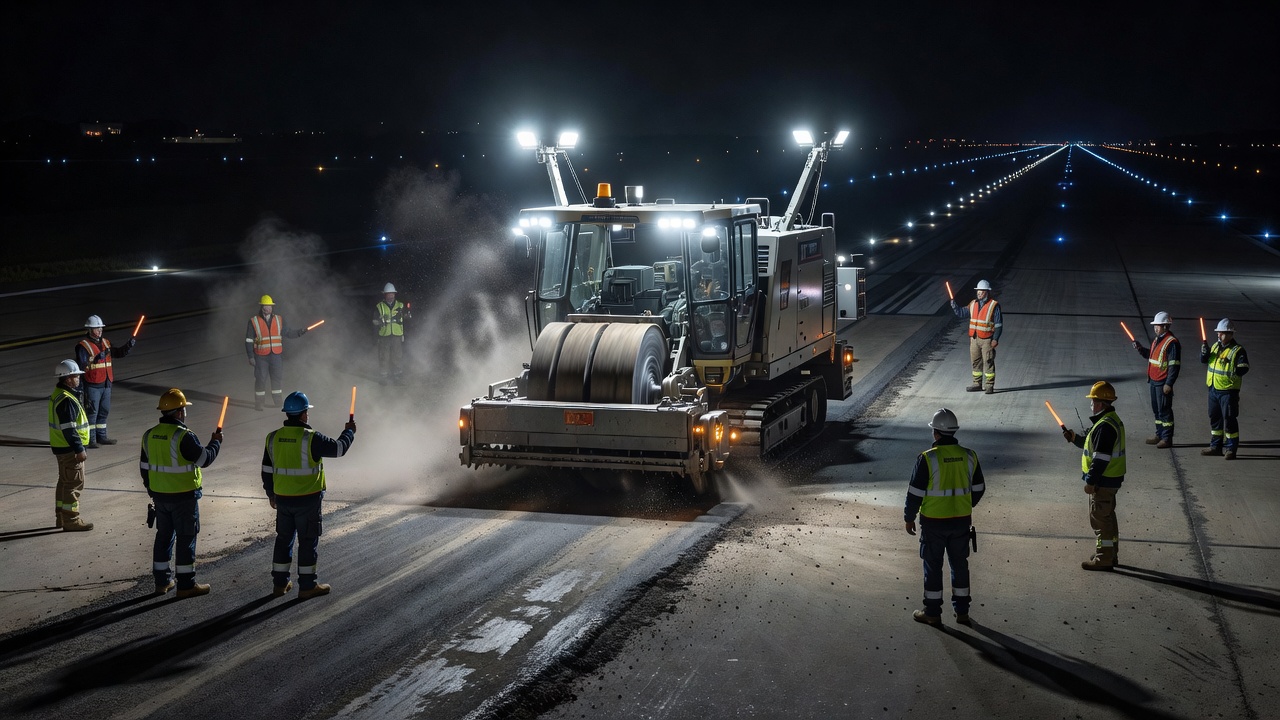
Limited Possession Times
The most significant constraint is limited pavement possession time. Runways are typically available for closure only during nighttime hours — often 6-10 hours per shift (e.g., 10 PM to 7 AM). On air carrier airports, runway closures beyond scheduled maintenance windows can cause flight delays, diversions, and significant airline disruption costs. FAA Order 7210.3 (Facility Operation and Administration) requires coordination between airport operators, air traffic control, and airlines at least 72 hours before any runway closure.
Work sequencing for possession-limited projects requires:
Phased construction: Runways are closed in segments rather than full length. The construction is sequenced so that the remaining runway length is adequate for emergency operations (typically 3,000-5,000 ft minimum).
Nightly mobilization and demobilization: All personnel, equipment, and materials must be cleared from the movement area and the pavement restored to operational condition before the morning first departure. Any equipment left on the airside after the possession window expires creates a safety hazard.
Cure time constraints: Materials must achieve sufficient strength for aircraft loading within hours. Rapid-set materials (e.g., high-early-strength HMA using polymer-modified binders, or rapid-set concrete with accelerating admixtures achieving 300-400 psi flexural strength in 4-6 hours) are specified.
Weekend/seasonal closures: Limited full closures may be scheduled during low-traffic periods. Typical full-runway closures are restricted to 48-72 hours on weekends at medium-hub airports, or extended seasonal windows at general-aviation airports.
Foreign Object Debris (FOD) Control
FOD control is a critical safety requirement during airport pavement rehabilitation. Loose pavement material, construction debris, tools, and equipment components on active movement areas can be ingested into aircraft engines or damage tires, causing catastrophic failures. ICAO Doc 9137 (Airport Services Manual, Part 8 — Operational Services) and FAA AC 150/5210-24 (Airport Foreign Object Debris Management) provide guidance for FOD prevention during construction.
FOD control measures during rehabilitation include:
Continuous mechanical sweeping: Walk-behind sweepers and truck-mounted rotary broom sweepers operate continuously behind milling and paving operations.
Magnets and vacuum systems: Magnetic sweepers remove ferrous debris. Industrial vacuum systems remove fine debris and foreign objects.
Magnet-mediated sweeping vehicles: Purpose-built FOD-control vehicles (e.g., FOD*BOSS) use high-power magnets and collection systems operating at 5-10 mph.
Pre-flight FOD walks: Before opening the runway after nightly possession, a formal FOD walk is performed — typically 5-10 people walking shoulder-to-shoulder across the full width, scanning the surface for debris.
Tool control: All tools are accounted for using shadow boards with foam cutouts and tethers. Lost-tool protocols require possession time extension until the tool is recovered.
Material storage: Stockpiles are located outside the runway strip. Material transport routes avoid crossing active taxiways unless under escort.
Safety and Operational Constraints
FAA AC 150/5370-2G (Operational Safety on Airports During Construction) establishes mandatory safety standards for airfield construction. Key constraints for rehabilitation projects:
Runway Safety Area (RSA) protection: No construction equipment or material storage within the RSA (150-500 ft beyond runway end depending on design code) without waiver.
Taxiway closure restrictions: At least one taxiway route to each runway must remain available. Full taxiway systems are not closed simultaneously.
Instrument Landing System (ILS) critical areas: Construction equipment within ILS critical and sensitive areas can cause signal interference and must be coordinated with air traffic control and navigation aids specialists.
Lighted signage: Temporary runway closure markings require FAA-approved lighting — red lights at closure points, barricades with flashing lights, and temporary taxiway centerline lights for rerouted traffic.
Wildlife hazards: Open trenches, ponding water, and fresh milling operations attract birds and wildlife. Wildlife mitigation measures per FAA AC 150/5200-33 (Hazardous Wildlife Attractants on or Near Airports) are required.
Emergency access: Firefighting vehicles must have access to all aircraft movement areas at all times. Temporary haul roads may be required to maintain access.
Material Selection for Possession-Constrained Projects
The limited possession time dictates material selection. For hot-mix asphalt rehabilitation on airport runways:
High-early-strength HMA: Uses PG 76-22 or PG 82-22 polymer-modified binder with a compaction temperature of 300-325°F. The mix achieves 90% of target density within 2 hours of laydown and can open to aircraft within 4 hours at ambient temperatures above 50°F.
Rapid-set HMA: Uses specialized binder systems with chemical additives that accelerate strength gain. Some proprietary systems can accept aircraft loading within 2-3 hours of placement.
Recycling-based approaches: CIR and FDR have significant schedule advantages. The recycled base layer does not require structural strength for aircraft loading until the HMA wearing surface is placed in a subsequent shift. The HMA surface course, placed the following night, only needs to be 1.5-2 inches thick — minimizing cooling time.
Precast concrete panels: For concrete rehabilitation, precast prestressed panels can be placed and grouted within a single shift, opening to traffic within 6-8 hours. The Sink (2014) ACRP Report 133 on precast pavement systems documented successful application at Chicago O’Hare, Newark Liberty, and other major airports.
Rehabilitation Design and Specifications
Rehabilitation design is performed using FAA FAARFIELD (FAA Rigid and Flexible Iterative Elastic Layer Design) software, which is the required program for all FAA-funded airport pavement projects. FAARFIELD is based on elastic layer theory and uses the cumulative damage concept (Miner’s hypothesis) to compute design thickness based on traffic load spectra.
Overlay Design in FAARFIELD
For asphalt overlay design on existing flexible pavements, FAARFIELD uses the following process (per FAA AC 150/5320-6G Figure 5-3):
Define existing pavement structure: Input existing layer types and thicknesses from as-built records, GPR survey, or test pits.
Assign effective structural condition: Based on PCI and FWD results, FAARFIELD reduces the effective structural coefficient of existing layers. Pavements in good condition (PCI > 70) retain 80-100% effective value; fair condition (PCI 55-70) retains 50-80%; poor condition (PCI < 55) retains 25-50%.
Evaluate structural life: FAARFIELD computes the CDF of the existing pavement for projected traffic. CDF > 1.0 means the pavement has exceeded its design life.
Design overlay: FAARFIELD computes the required overlay thickness in 0.5-inch increments using an iterative approach, adjusting the overlay thickness until the CDF at the bottom of the critical pavement layer is less than 1.0.
For asphalt overlay on existing rigid pavements, the existing concrete slab is evaluated using FWD to determine load transfer efficiency (LTE). If LTE > 70%, the concrete is treated as a structural layer with a reduced modulus; if LTE < 70%, the concrete is treated as a cracked/broken layer or rubbleized.
Construction Specifications
Rehabilitation specifications follow standard FAA P-401 (HMA) or P-501 (PCC) specifications unless project-specific modifications are needed for possession-constrained construction. Key specification elements for rehabilitation projects:
Milling tolerances: Surface tolerance of ±0.125 inches (3 mm) over 10 feet (3 m) after milling per FAA specification Item P-603.
Tack coat: SS-1, SS-1h, or CSS-1 emulsion applied at residual rate of 0.05-0.15 gal/sy depending on surface condition. For milled surfaces, higher application rates (0.10-0.15 gal/sy residual) are used.
Compaction: HMA overlays on runways require 96-98% of theoretical maximum density (Rice density) per FAA P-401. For thin lifts (1.5-2 inches), rolling patterns must be carefully optimized to achieve density within temperature windows.
Surface tolerance: After overlay, surface variation shall not exceed ±0.125 inches (3 mm) when tested with a 16-foot straightedge per FAA Item P-401 Section 3.5.
Friction testing: Runway friction testing per FAA AC 150/5320-12C is required before opening. Continuous friction measuring equipment (CFME) such as the Saab Friction Tester (SFT) or GripTester must achieve minimum Mu values per ICAO Annex 14.
FAA Item Specifications for Rehabilitation
FAA Item
Description
Application
P-101
Preparation of subgrade
For partial reconstruction with subgrade treatment
P-152
Excavation and embankment
For reconstruction requiring grade changes
P-208
Aggregate base course
For base restoration in reconstructed areas
P-401
Plant mix bituminous pavements
HMA overlay and inlay up to 6-inch depth
P-402
In-place bituminous pavement recycling
CIR and FDR projects
P-501
Portland cement concrete pavement
Whitetopping and unbonded concrete overlay
P-502
Precast concrete pavement
Rapid replacement of concrete panels
P-603
Cold planning (milling)
Mill and inlay, surface preparation for overlay
P-609
Crack repair
Before overlay or surface treatment
P-610
Joint sealing
Before overlay on concrete pavements
P-620
Runway grooving
After overlay for friction restoration
Post-Rehabilitation Inspection and Monitoring
Rehabilitation projects require systematic post-construction inspection and ongoing performance monitoring to ensure the treatment achieves its intended service life.
Acceptance Inspection
Per FAA AC 150/5370-10 (Standards for Specifying Construction of Airports), acceptance inspection includes:
Thickness verification: Core samples at 1 per 500 square yards minimum per P-401 Section 4.5. Average thickness must equal or exceed design thickness with no individual core more than 0.5 inch below design.
Density testing: Nuclear density gauge or core bulk specific gravity at 1 per 600 square yards per lift. Minimum 96% of Rice density.
Smoothness testing: 16-foot straightedge surface profile per P-401 Section 3.5. Maximum deviation of 0.125 inches (3 mm). Areas exceeding tolerance require diamond grinding or removal and replacement.
Friction testing: Runway friction coefficient measured using CFME per ICAO Annex 14 and FAA AC 150/5320-12C. Minimum average friction of 0.5 (Mu) at 40 mph is required for runways.
Pavement marking inspection: Reflectivity, color, thickness, and dimensional accuracy per FAA AC 150/5340-1.
Performance Monitoring
After rehabilitation, the pavement enters a new lifecycle phase. Performance monitoring per FAA AC 150/5380-7B includes:
PCI survey at 3-year intervals: The first PCI survey should be performed 2-3 years after rehabilitation to establish the initial post-rehabilitation condition baseline.
FWD testing at 5-year intervals: Structural evaluation to track modulus deterioration over time and identify when the next rehabilitation cycle should be planned.
IRI measurement at 3-year intervals: Ride quality monitoring to detect developing roughness before it affects operations.
Friction testing at 6-month intervals: Runway friction monitoring per FAA AC 150/5320-12C requirements for FAR Part 139 airports. Friction deterioration signals the need for surface restoration.
Pavement Management System Updates
Rehabilitation data must be entered into the airport pavement management system (APMS) or FAA PAVEAIR system, including:
Treatment type, date, and cost
Design parameters (overlay thickness, mix design)
Acceptance test results
Revised design life and expected rehabilitation cycle
Updated pavement structure layer inventory
The APMS uses this data to update deterioration curves and optimize the timing and type of future maintenance and rehabilitation interventions.
Performance Prediction
The expected service life of rehabilitation treatments depends on treatment type, structural adequacy, construction quality, loading, and climate.
Expected Service Lives
Based on FAA, ACRP, and industry performance data:
Rehabilitation Type
Expected Service Life
Typical Extended Life
Thin HMA overlay (1.5-2 in)
8-12 years
10-15 years with preventive maintenance
Structural HMA overlay (3-6 in)
15-20 years
20-25 years with preventive maintenance
Mill and inlay (2-4 in)
10-15 years
12-18 years with maintenance
Hot in-place recycling
8-12 years
10-15 years with slurry seal
Cold in-place recycling + overlay
15-20 years
20-25 years
Full-depth reclamation + overlay
15-25 years
20-30 years
Unbonded concrete overlay
20-30 years
30-35 years
Whitetopping (6-8 in)
20-25 years
25-30 years
Diamond grinding
8-12 years
10-15 years with joint sealing
Deterioration Modeling
Post-rehabilitation pavement deterioration follows an S-shaped curve similar to new construction but with an initially higher condition (starting PCI typically 90-95 for overlay, 85-90 for recycling treatments). The rate of deterioration is influenced by:
Structural adequacy: Pavements designed with CDF < 0.5 at design traffic show 30-50% slower deterioration than those designed at CDF = 1.0.
Load magnitude and frequency: Heavy aircraft such as Boeing 777-300ER and Airbus A380 cause exponentially greater structural damage per pass compared to narrow-body aircraft. The FAA equivalent annual departures (EAD) concept in FAARFIELD accounts for this mix.
Climate factors: Freeze-thaw cycles, precipitation, and temperature extremes accelerate deterioration. Airports in freeze-thaw zones (ACI Climate Zones I-IV) experience 1.5-2x faster surface deterioration than those in non-freeze regions.
Construction quality: Pavements achieving > 96% compaction show 20-30% longer service life than those at 92-94% compaction.
Maintenance effectiveness: Timely crack sealing and surface treatments during the first 5-7 years after rehabilitation can extend service life by 30-50%.
Performance Feedback for Future Rehabilitation Planning
Performance data collected through post-rehabilitation monitoring feeds back into the pavement management system’s deterioration models, allowing more accurate prediction of optimal rehabilitation timing for the next cycle. This closed-loop process — inspection, analysis, treatment, monitoring, and re-analysis — is the foundation of effective pavement management as defined in FAA AC 150/5380-7B and ICAO Airport Pavement Management System (APMS) guidance.
Airport Cooperative Research Program (ACRP) Report 44 provides a comprehensive framework for integrating pavement management into overall airport asset management, including rehabilitation performance tracking, budget optimization, and lifecycle cost minimization across the entire pavement network.
Frequently Asked Questions
Pavement rehabilitation is the process of restoring or increasing the structural capacity of an existing airport pavement to extend its service life. It includes engineered interventions such as hot-mix asphalt overlays, concrete overlays, milling and inlay, cold in-place recycling, full-depth reclamation, whitetopping (concrete overlay on existing asphalt), and partial reconstruction. Rehabilitation is triggered when PCI drops below 55-70, IRI exceeds operational thresholds, or structural testing (FWD) shows inadequate load-carrying capacity for current or projected aircraft traffic.
Pavement maintenance consists of routine activities that preserve the existing pavement and slow its rate of deterioration — crack sealing, chip sealing, pothole patching, joint sealing, and minor surface repairs. Maintenance does not increase structural capacity. Rehabilitation involves structural interventions that add load-carrying capacity or restore significant lost structural value — overlays, milling and replacement, recycling, whitetopping, or partial-depth reconstruction. Rehabilitation is more costly but extends service life by 10-20+ years. Reconstruction is the complete removal and replacement of all pavement layers down to the subgrade.
Per FAA AC 150/5380-7B and ASTM D5340, PCI values range from 0 (failed) to 100 (excellent). PCI 70-100 is good — preventive maintenance is sufficient. PCI 55-70 is fair — rehabilitation should be considered and planned. PCI 40-55 is poor — structural rehabilitation is typically required. PCI below 40 is very poor to failed — major rehabilitation or reconstruction is needed. Many airport pavement management systems use PCI 55-60 as the threshold for triggering rehabilitation planning and PCI 40 as the threshold for mandatory intervention.
The main rehabilitation types include: (1) Asphalt overlay — placing new HMA over existing pavement, with or without milling for grade control. (2) Mill and inlay — removing a specified depth of existing material (typically 2-4 inches) and replacing with new HMA. (3) Concrete overlay — unbonded concrete overlay on existing concrete, or whitetopping on asphalt. (4) Cold in-place recycling (CIR) — milling 3-5 inches, treating with foamed asphalt or emulsion, and re-laying as a new stabilized base layer followed by HMA surface. (5) Full-depth reclamation (FDR) — pulverizing the full asphalt layer and portion of base, stabilizing with cement or asphalt, and overlaying. (6) Partial reconstruction — removing and replacing selected deteriorated layers while retaining usable lower layers.
Lifecycle cost analysis (LCCA) for airport pavements is governed by FAA Order 5100.38C and AC 150/5320-6G. LCCA compares alternative rehabilitation strategies over a 20-40 year analysis period using net present worth (NPW) calculations. All direct costs (initial construction, future maintenance and rehabilitation, salvage value) and indirect costs (user delay costs, operational disruption) are included. A 4% discount rate is standard for FAA-funded projects. The alternative with the lowest total NPW is typically selected, subject to performance and risk evaluation.
Airport pavement rehabilitation is subject to unique constraints not found in highway applications. Limited possession times — runways may only be available for 6-10 hours per night, often from midnight to 6 AM. Full closures may only be possible during low-traffic seasons. Strict FOD (foreign object debris) control requirements mandate continuous sweeping and inspection. Safety zones around active taxiways require temporary barrier systems. Pavement surface friction must meet ICAO Annex 14 standards immediately after construction. Lighted signage, runway edge lights, and instrument landing system (ILS) sensitive areas must be protected. Emergency vehicle access must be maintained at all times.
The Falling Weight Deflectometer (FWD) is the primary nondestructive test device for airport pavement structural evaluation per FAA AC 150/5320-6G Appendix C. FWD applies an impulse load simulating an aircraft landing gear (typically 12,000-60,000 pounds) and measures the resulting pavement deflection basin using geophones. Deflection data is analyzed using backcalculation to determine in-situ layer moduli of the surface, base, subbase, and subgrade layers. This data is then used in FAARFIELD software to design overlay thickness requirements. FWD evaluation identifies weak layers, void detection, and load transfer efficiency at joints in rigid pavements.
FAA AC 150/5320-6G Section 4.10 specifies surface preparation requirements for overlays: (1) Full-depth repairs of localized failures must be completed prior to overlay. (2) Cracks wider than 3 mm (0.125 in) must be sealed. (3) The existing surface must be cleaned of debris, oil, and rubber deposits. (4) A tack coat is applied to existing asphalt surfaces at a rate of 0.05-0.15 gal/sy. (5) For concrete pavements receiving asphalt overlays, a stress-absorbing membrane interlayer (SAMI) or bond breaker is typically required. (6) Milling may be needed to remove surface irregularities, restore crown and grade, and improve bond conditions. (7) Existing pavement must be structurally adequate — any failed areas require repair before overlay placement.
Need pavement rehabilitation planning?
TarmacView provides comprehensive pavement inspection data to support rehabilitation decision-making. Our AI-driven distress detection helps identify critical areas requiring structural intervention. Contact our team for a demo.
Reconstruction is the complete removal and replacement of a pavement structure from subgrade up, performed when the pavement has reached terminal condition and ...
Reconstruction is the complete removal and replacement of a pavement structure from subgrade up, performed when the pavement has reached terminal condition and ...
Preventive maintenance is a planned strategy of cost-effective treatments applied to pavements in good-to-fair condition to slow deterioration and extend servic...
29 min read
Pavement maintenance
Airport infrastructure
+3
Cookie Consent We use cookies to enhance your browsing experience and analyze our traffic. See our privacy policy.