Soil Nail Wall
Soil nailing is an in-situ ground reinforcement technique where closely spaced steel bars are grouted into a soil slope or excavation face as construction proce...
23 min read
structures
geotechnical
+4
Retaining walls are engineered earth-retaining structures that hold back soil or rock from buildings, bridge approaches, roadways, and airport facilities, preventing erosion and providing grade separation. Wall condition — cracking, tilting, bulging, drainage failure, corrosion, and facing deterioration — is a recurring inspection item under FHWA and AASHTO protocols. Covers wall types (gravity, cantilever, counterfort, anchored, MSE, soil nail, sheet pile), distress modes, drainage systems, inspection criteria, repair methods, and FHWA/AASHTO design guidance.
{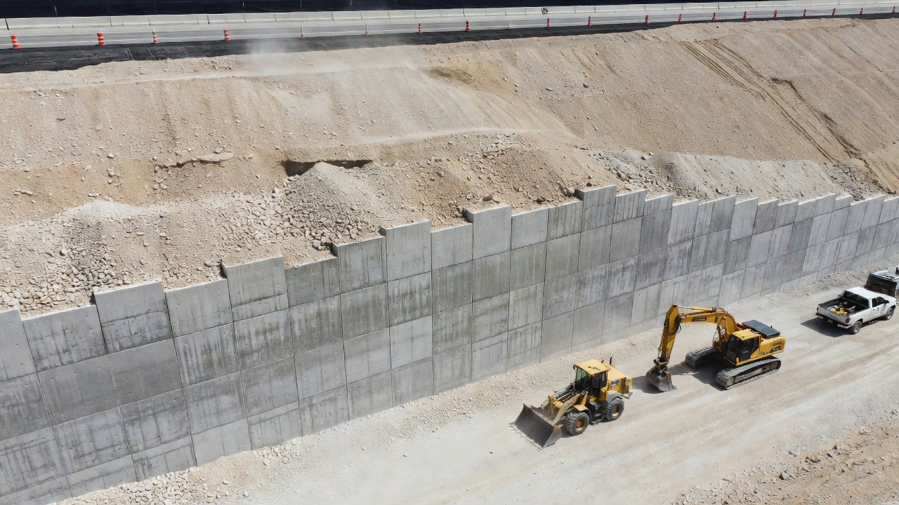
A retaining wall is an engineered earth-retaining structure designed to hold back soil, rock, or other unconsolidated materials at a slope steeper than the material’s natural angle of repose. Retaining walls are fundamental components of transportation infrastructure, providing grade separation — the maintenance of a difference in elevation between two ground surfaces — while resisting lateral earth pressures, surcharge loads from vehicles or adjacent structures, and hydrostatic forces from groundwater. The structure functions by transferring these lateral forces to a foundation system through its self-weight, flexural resistance, or a reinforced soil mass.
The primary functions of retaining walls in infrastructure include: (1) supporting vertical excavations for roadway cuts and fills, allowing highways and railways to traverse sloped terrain without excessive earthwork; (2) proventing erosion of embankment slopes by armoring the cut face against rainfall, runoff, and freeze-thaw action; (3) protecting adjacent structures from slope instability and landslide movement; (4) creating usable land on sloped sites for airport aprons, building pads, parking structures, and industrial facilities; (5) supporting bridge approaches as abutments that retain the approach fill while transferring bridge loads to foundations; and (6) providing channel confinement for rivers and drainage channels to control flood flows and prevent bank erosion.
Retaining walls are classified by their structural behavior and construction method into seven primary types: gravity walls, cantilever walls, counterfort walls, mechanically stabilized earth (MSE) walls, anchored walls, soil nail walls, and sheet pile walls. Each type has distinct load-resistance mechanisms, height ranges, cost profiles, and appropriate applications. The selection of wall type depends on retained height, soil conditions, groundwater regime, available right-of-way, construction access, service life requirements, and economic considerations.
{{
Gravity retaining walls resist lateral earth pressure entirely through their own self-weight and the weight of any soil bearing on the wall’s base or heel. These walls are massive concrete or stone masonry structures with typical base width to height ratios of 0.5 to 0.7. A gravity wall for a 4-meter retained height would require a base width of 2.0 to 2.8 meters. The wall cross-section is trapezoidal — wider at the base and narrower at the top — with the minimum top width governed by construction tolerances and frost protection requirements, typically 300 mm for unreinforced concrete.
Gravity walls rely on the weight of the wall material and the weight of soil on the heel to generate stabilizing moments that resist overturning. The wall must satisfy three stability criteria per AASHTO LRFD: (1) overturning — factored stabilizing moments must exceed factored overturning moments by a minimum ratio of 2.0 for service loads and 1.5 for strength loads; (2) sliding — factored horizontal resisting force (friction between base and foundation soil plus passive resistance at the toe) must exceed factored driving lateral force by a minimum ratio of 1.5; and (3) bearing capacity — maximum vertical pressure at the toe must not exceed the allowable bearing capacity of the foundation soil, with the resultant force located within the middle third of the base width to prevent tension at the heel.
Gravity walls are most economical for low to moderate heights — typically 1.5 to 6 meters. Above 6 meters, the material volume required makes them uneconomical compared to cantilever or MSE alternatives. Gravity walls are common for roadway retaining applications, landscaping features, and historical or architectural settings where a massive stone appearance is desired. Crib walls and gabion walls are variants of gravity walls that use interlocking timber, concrete, or wire mesh baskets filled with stone to achieve weight while providing drainage and flexibility.
Cantilever retaining walls are reinforced concrete structures consisting of a vertical stem and a horizontal base slab — typically an L-shaped or inverted T-shaped cross-section. The stem cantilevers from the base, and the base includes a toe projecting forward and a heel projecting backward beneath the retained fill. The wall resists lateral earth pressure through flexural resistance — the stem bends under soil pressure, and the base distributes vertical loads to the foundation. The weight of soil bearing on the heel contributes to overturning resistance.
Cantilever walls are the most common type of concrete retaining wall in transportation infrastructure for heights ranging from 3 to 9 meters. Above 9 meters, cantilever walls become uneconomical as stem moments require excessive reinforcement and section depth, and counterfort walls become preferable. Typical dimensions for a cantilever wall include: stem thickness at the base of 7 to 10 percent of wall height, stem thickness at the top of 200 to 300 mm, base width of 0.4 to 0.7 times wall height, toe projection of 20 to 33 percent of base width, and heel projection of 25 to 40 percent of base width.
The structural design of cantilever walls per AASHTO LRFD Section 11 involves: (1) computing active earth pressure using Rankine or Coulomb theory based on soil friction angle and wall friction; (2) calculating stem moments from lateral earth pressure and any surcharge loads — the stem is designed as a cantilever beam fixed at the base; (3) designing flexural reinforcement in the stem for maximum moment at the base-to-stem junction; (4) checking shear capacity at the stem-base connection — shear typically governs at the base for walls taller than 6 meters; (5) designing temperature and shrinkage reinforcement in exposed faces; (6) sizing the base slab reinforcement for toe pressure reaction and heel load from soil weight; (7) verifying development length for reinforcement bars at the stem-base intersection; and (8) detailing construction joints and drainage provisions including weep holes through the stem.
Counterfort retaining walls are cantilever walls with the addition of thin vertical concrete webs — called counterforts — placed at regular intervals (typically 3 to 6 meters center-to-center) on the back side of the stem. The counterforts connect the stem to the base slab, creating a T-beam action where the stem acts as a continuous slab spanning horizontally between counterforts, and the counterforts themselves act as vertical cantilever beams transmitting forces to the base. This structural system significantly reduces the stem bending moments and reinforcement compared to a plain cantilever wall of the same height.
Counterfort walls are selected for heights exceeding 8 to 10 meters, where a plain cantilever wall would require excessively thick stems and heavy reinforcement. The counterforts effectively convert the wall from a one-way cantilever system to a two-way slab system, reducing stem thickness by 30 to 50 percent compared to an equivalent cantilever design. A typical counterfort wall for a 12-meter height would have a stem thickness of 400 to 500 mm (versus 900 to 1200 mm for a plain cantilever), counterfort thickness of 300 to 400 mm, and counterfort spacing of 4 to 6 meters.
Counterfort walls have a higher construction complexity than plain cantilever walls due to the formwork and reinforcement detailing required for the counterfort-stem-base junctions. However, for tall walls, the material savings in concrete and steel typically offset the increased labor cost. Counterfort walls are used in deep highway cuts, railway retaining applications, bridge abutments for tall approaches, and waterfront structures. Buttress walls are the opposite configuration — counterforts placed on the exposed (front) face of the wall rather than the back side, used where space behind the wall is constrained or architectural expression is desired.
Mechanically Stabilized Earth (MSE) walls are composite gravity retaining structures that use facing elements, soil reinforcements, and select granular backfill to form a coherent reinforced soil mass capable of supporting substantial loads. The reinforced soil mass acts as a gravity structure — its self-weight resists lateral pressures from earth, surcharges, and seismic events. MSE walls are the most prevalent retaining wall type in modern US transportation infrastructure, accounting for over 60 percent of new retaining wall construction annually per FHWA statistics.
The MSE wall concept was developed by French engineer Henri Vidal in the 1960s, with the first commercial Reinforced Earth® wall constructed in France in 1966. The technology was introduced to the United States in 1972, and the first US highway installation was on California State Route 39 in 1974. Since then, MSE walls have been constructed for heights exceeding 40 meters at some mining and infrastructure projects. The economic advantage of MSE walls over conventional reinforced concrete walls increases with height — cost savings of 30 to 50 percent or more compared to cantilever walls at moderate heights.
MSE walls rely on the tension-resisting mechanism of soil reinforcement placed in layers within the backfill. The reinforcement restrains soil deformation by developing pullout resistance through friction and bearing against the soil particles. This creates a composite material with apparent cohesion in the reinforced zone — the reinforced soil mass behaves as a coherent gravity block with its own internal stability. The three essential components work together as described in the section below.
{{
Anchored retaining walls are thin structural wall elements — typically soldier piles with lagging, sheet piles, or cast-in-place concrete — stabilized by post-tensioned ground anchors (tiebacks) drilled into the retained soil or rock mass behind the wall. The anchors are installed at an angle (typically 15 to 30 degrees below horizontal), drilled through the wall face into stable ground, grouted in place, and tensioned to provide active lateral support. The tensioning pre-compresses the retained ground, creating a zone of increased stress that reduces wall deflection.
Anchored walls are used for deep excavations in urban environments, landslide stabilization, steep cut slopes, and retrofit of existing failing walls. The key advantage is that anchors allow construction of economical thin walls at significant heights — up to 15 to 20 meters is common, and deeper excavations are possible with multiple anchor rows. A typical anchored wall for a 12-meter excavation might use three rows of anchors at vertical spacings of 3 to 4 meters, each anchor providing 300 to 1000 kN of design load depending on ground conditions.
The design of anchored walls per AASHTO LRFD Section 11 and FHWA-RD-97-130 (Ground Anchors and Anchored Systems) involves: (1) determining anchor spacing and inclination based on wall geometry and retained height; (2) computing anchor design loads from lateral earth pressure distribution and required factor of safety; (3) sizing the anchor bond length (grouted zone) based on ground-to-grout bond strength parameters — bond stress values range from 0.3 to 1.0 MPa in soil and 0.5 to 2.0 MPa in rock; (4) designing the anchor tendon (typically high-strength steel strands or bars) for tensile capacity; (5) verifying global stability of the anchored wall system including potential failure surfaces extending behind the anchor zone; (6) designing the wall facing to span between anchor rows; and (7) specifying corrosion protection per PTI (Post-Tensioning Institute) requirements — encapsulated double-corrosion protection is standard for permanent anchors.
Soil nail walls are in-situ reinforced soil structures constructed by installing passive steel bars (nails) into the retained ground as excavation proceeds from top to down. The nails are typically 20 to 40 mm diameter deformed steel bars, installed into drilled holes at a slight downward inclination (10 to 20 degrees), and fully grouted along their length. A shotcrete facing (100 to 150 mm thick) with welded wire mesh is applied to the excavated face to provide surface support. Soil nail walls are constructed from the top down — each excavation lift of 1 to 2 meters is followed by nail installation, shotcreting, and advancement to the next level.
Soil nails are passive elements — they are not tensioned after installation. Load is developed in the nails as the retained ground deforms during subsequent excavation lifts. The nail-soil interaction generates pullout resistance through the grout-to-ground bond along the nail length. The system functions as a coherent reinforced soil mass, similar in behavior to MSE walls but constructed in-situ rather than built from the bottom up.
Soil nail walls are most suitable for cut slopes in soil conditions that can stand unsupported for short periods (typically 1 to 2 meters) during excavation. They are widely used for highway cut stabilization, bridge abutment wing walls, tunnel portal excavations, and landslide repairs. Maximum practical height is typically 15 to 20 meters, though taller walls have been constructed with multiple nail rows. Soil nail walls are generally more economical than anchored walls for moderate heights due to the elimination of anchor hardware, stressing operations, and corrosion protection systems.
The FHWA design manual for soil nail walls (FHWA GEC-7, Soil Nail Walls Design Manual) specifies design procedures including: (1) determining nail length based on internal stability analysis using a limit equilibrium approach with potential failure surfaces passing through the reinforced zone; (2) computing nail pullout capacity from grout-ground bond stresses; (3) verifying external stability (overturning, sliding, bearing capacity); (4) designing the shotcrete facing for flexure and punching shear at nail heads; and (5) providing permanent drainage behind the facing — FHWA GEC-7 calls for through-facing weep drains at 5 to 10 foot spacing to prevent hydrostatic pressure buildup that drives shotcrete debonding.
Sheet pile walls are continuous walls of interlocking steel, vinyl, or precast concrete piles driven into the ground to create a vertical earth retention system. The piles are driven using vibratory or impact hammers and interlock along their edges to form a continuous barrier. Sheet pile walls resist lateral earth pressure through bending resistance of the pile section and, where used, tieback anchors or brace systems. In cantilever configuration, the wall acts as a vertical beam fixed in the ground below the excavation level.
Steel sheet piles are the most common type, manufactured in standard sections including Z-type, U-type, and flat web profiles. Section modulus values range from 1,200 to 4,500 cm³/m of wall, with typical pile lengths of 6 to 20 meters. Vinyl sheet piles are used for low-height applications (up to 3 meters) where chemical resistance is needed or where aesthetics require a colored wall. Concrete sheet piles are prestressed and used for marine structures and permanent walls in aggressive environments.
Sheet pile walls are used for: (1) temporary excavation support in foundation construction and utility trenches; (2) cofferdams for bridge pier construction in water; (3) flood walls and levee systems; (4) waterfront structures including quay walls, dock walls, and seawalls; (5) cutoff walls for groundwater control; and (6) landslide stabilization in soft ground. Sheet pile walls are advantageous where rapid installation is required, where vibration is acceptable, and where the wall must be watertight.
Design of sheet pile walls per AASHTO and FHWA methodology involves: (1) computing lateral earth and water pressures — water pressure often dominates in waterfront applications; (2) determining cantilever embedment depth required for fixity against rotation and lateral movement — typical embedment depth is 1.2 to 1.5 times the exposed height for cantilever walls; (3) sizing the pile section modulus from maximum bending moment; (4) verifying global stability of the retained ground; and (5) designing anchor systems if required — anchored sheet pile walls use one or two rows of tieback anchors to reduce pile section requirements and wall deflection.
The facing of an MSE wall serves three functions: (1) containing the backfill at the exposed face to prevent soil raveling; (2) transferring reinforcement load from the reinforcement strips or grids into the soil mass through the connection to the facing; and (3) providing architectural finish and weathering protection. Facing elements are typically precast concrete panels in standard cruciform (5 ft × 5 ft), rectangular (5 ft × 10 ft), or square geometries. Panel thickness ranges from 100 to 200 mm depending on wall height, with thicker panels required for tall walls and architectural finishes.
The facing panels have embedded connection devices for attaching the soil reinforcement — typically bolted cleats, loop connectors, or slot-and-key systems for steel strips, and PVC sleeve connections for geosynthetic straps. Panels are placed on levelling pads of lean concrete or compacted granular material to provide uniform bearing. The panels are separated by bearing pads or compressible joints at the connection points to accommodate differential movements between adjacent panels during backfill placement and service.
Alternative facing types include: (1) wire mesh facings (TerraTrel® and GeoTrel® systems) — galvanized steel wire mesh baskets that form a flexible, vegetated face; (2) full-height concrete panels — used where architectural treatments such as ashlar stone, brick, or formliner finishes are required; (3) block facings — modular concrete blocks that interlock without mechanical reinforcement connections, used in low-height segmental retaining walls; and (4) welded wire facings — used for temporary structures or steep reinforced slopes where facing loads are low.
Soil reinforcements are the tension-resisting elements that create the composite reinforced soil mass. Two categories exist: extensible reinforcements (geosynthetics) and inextensible reinforcements (steel strips and grids).
Steel strip reinforcements are typically 50 mm (2 inch) wide by 4 mm thick galvanized steel strips with high-adherence (HA) ribbing — periodic deformations rolled into the strip surface to increase soil-to-strip bond. Strips are placed at vertical spacings of 500 to 750 mm and lengths varying from 0.7H at the top to a minimum of 0.7H at the base, where H is wall height. The minimum strip length is typically 3 meters, and the maximum is controlled by the retained soil zone. Connections to the facing are made through bolted cleats or loop connections. Steel grid reinforcements (ladder-type) use transverse bars welded to longitudinal members to provide increased pullout capacity from passive bearing resistance on the transverse bars.
Geosynthetic strip reinforcements (GeoStrap®) consist of high-tenacity polyester fibers encased in a polyethylene sheath, offering corrosion resistance in aggressive environments where galvanized steel would deteriorate. Geosynthetic reinforcement is extensible — it elongates more than steel under load, which affects the location of the maximum tension line within the reinforced mass. Extensible reinforcements typically require longer reinforcement lengths (0.8H to 1.0H) compared to steel reinforcements (0.7H), and the facing must be designed to accommodate greater deformations.
The reinforcement pullout capacity is the critical design parameter — it controls the required length and spacing. Pullout capacity depends on the effective overburden pressure, reinforcement width, coefficient of interaction (soil-to-reinforcement bond), and length of reinforcement embedded beyond the critical failure surface. Coefficients of interaction range from 0.8 to 1.0 for steel strips in granular backfill and 0.5 to 0.9 for geosynthetics depending on soil type.
Select backfill is the granular fill material placed within the reinforced zone of an MSE wall. The gradation, plasticity, electrochemical properties, and durability of the backfill are critical to MSE wall performance. The ideal select backfill is free-draining granular material with: (1) maximum particle size of 100 mm (4 inches); (2) not more than 15 percent passing the No. 200 sieve (0.075 mm); (3) plasticity index (PI) of 6 or less; (4) minimum friction angle of 34 degrees determined by direct shear testing; (5) low electrochemical aggressivity — resistivity of 3,000 ohm-cm or more, pH between 5.5 and 10, chloride content less than 100 ppm, and sulfate content less than 200 ppm.
The backfill material must be classified per the Unified Soil Classification System (USCS) as GW, GP, GM, SW, or SP — well-graded or poorly-graded gravels and sands with low fines content. On-site soils that meet these criteria can be used if they are processed to achieve the required gradation. Marginal backfill with higher fines content (up to 50 percent passing No. 200 sieve) can be used in some proprietary MSE systems with longer reinforcement lengths and spacings, but this requires additional design consideration and reduced corrosion service life assumptions per FHWA.
Recycled materials — including crushed concrete, reclaimed asphalt pavement (RAP), and recycled glass — can be used as MSE backfill when tested and approved by the engineer. Lightweight fill — including lightweight aggregate, low-density cellular concrete (LDCC), and foamed glass aggregate — is used where the MSE wall foundation requires reduced bearing pressure. Lightweight materials reduce vertical stress on soft foundation soils and can reduce wall settlement by 50 percent or more compared to conventional granular fill.
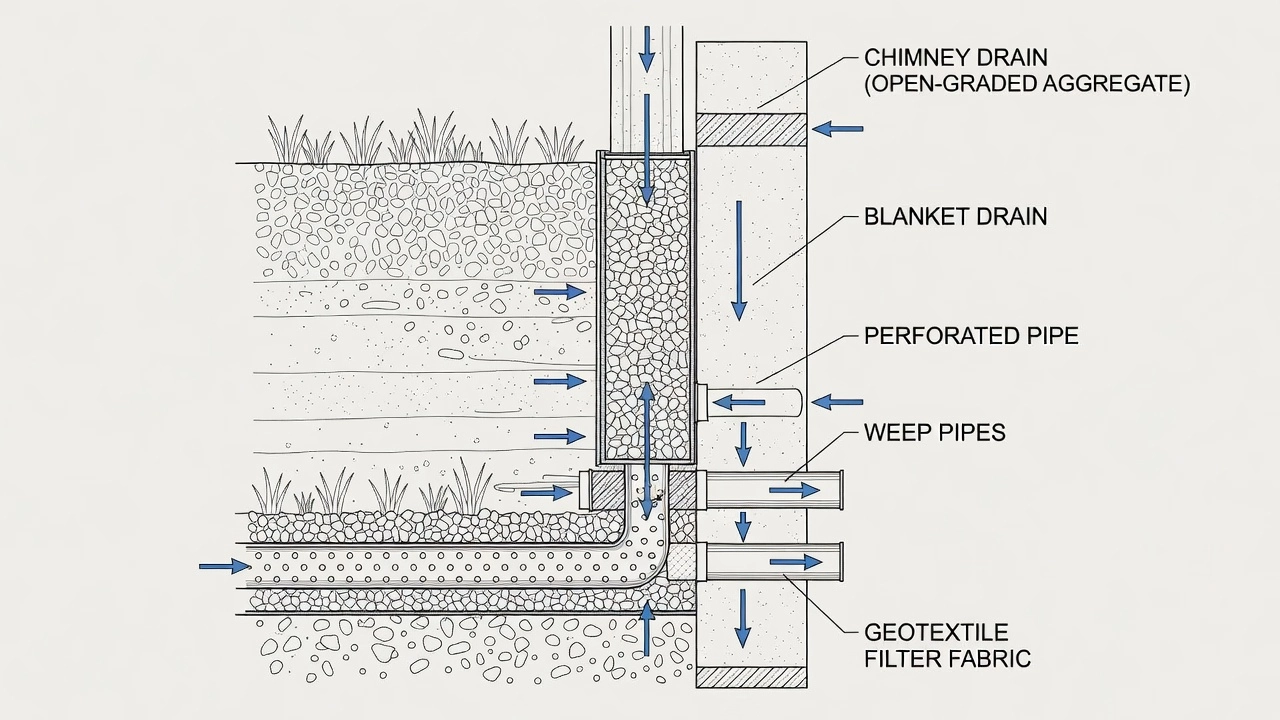
Drainage is the single most critical factor in retaining wall performance. Hydrostatic pressure from water accumulating behind a wall is the primary cause of retaining wall failure, capable of increasing lateral forces by 100 to 300 percent compared to drained conditions. AASHTO LRFD Section 11.10.8 explicitly makes wall drainage a design requirement — it is not optional. The standard drainage system for permanent retaining walls consists of a three-component hierarchy: chimney drain, blanket drain, and weep holes.
The chimney drain is a vertical drainage layer placed immediately behind the wall facing. It consists of AASHTO M 43 No. 57 open-graded aggregate (typically 25 to 4.75 mm stone) or a geocomposite drainage panel (dimpled HDPE sheet or three-dimensional polymer mesh wrapped in a nonwoven geotextile). The chimney drain collects water percolating downward through the backfill and routes it to the blanket drain at the base. The chimney extends from the top of the wall to the blanket drain at the base, with a minimum thickness of 300 mm for aggregate drains or 25 mm for geocomposite panels.
The blanket drain is a horizontal drainage layer placed along the base of the wall, extending from the heel of the base slab or the back of the chimney drain rearward into the retained fill. The blanket drain intercepts water that flows through the chimney drain and routes it to discharge points. A perforated PVC or HDPE pipe (typically 150 to 200 mm diameter) is placed within the blanket drain to collect and convey water to discharge outlets. The blanket drain minimum thickness is 300 mm of AASHTO No. 57 aggregate wrapped in an AASHTO M 288 Class 2 nonwoven geotextile filter to prevent soil migration and clogging.
Weep holes (also called weep drains or through-wall drains) are short PVC pipes set through the wall facing to daylight collected water by gravity. Standard weep holes are 2 to 4 inch (50 to 100 mm) diameter schedule 40 PVC pipes set at a 2 to 5 percent downward slope through the facing. Each weep is wrapped in an AASHTO M 288 Class 2 nonwoven geotextile filter sock or surrounded by a graded gravel pack per AASHTO M 43 to prevent soil migration into the drain. The outlet projects 150 to 300 mm (6 to 12 inches) beyond the facing face to prevent staining and is terminated with a splash block or riprap apron.
Weep hole spacing per FHWA-NHI-10-024 is typically 5 to 10 feet (1.5 to 3 meters) horizontally and 3 to 8 feet (1 to 2.5 meters) vertically, with closer spacing in zones of expected high seepage. Weeps are always placed at the lowest point of the wall to ensure complete drainage. The bottom weep row must be located at or near the base of the wall, immediately above the grade beam or levelling pad.
If the drainage system is absent, clogged, or undersized, hydrostatic pressure behind the wall will increase lateral forces to the point of failure. The FHWA study by Loehr et al. (2008) found that 72 percent of retaining wall failures studied had inadequate drainage as a primary or contributing cause. The Brahmaputra River retaining wall failure in India (2012) and the MSD Landfill wall failure in the US (2002) both had drainage as a critical factor. Surface drainage — including grading the backfill surface to direct runoff away from the wall top and providing a paved ditch or swale at the wall toe — is a complementary requirement to subsurface drainage.
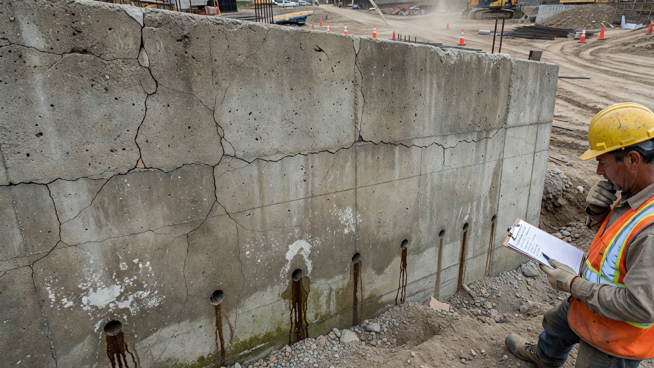
Cracking is the most visible distress indicator in concrete retaining walls. Cracks are classified by orientation and pattern: horizontal cracks near the stem-to-base junction indicate flexural overstress from excessive lateral pressure or inadequate reinforcement; vertical cracks may result from thermal expansion, shrinkage, or differential foundation settlement; diagonal cracks typically indicate shear overstress or differential movement; pattern cracking (map cracking) indicates surface shrinkage or material deterioration; and crack branching — multiple cracks radiating from a point — indicates concentrated stress from a localized defect.
Per FHWA retaining wall inspection protocols, crack widths exceeding 0.3 mm (1/64 inch) for aesthetic reasons and 0.5 mm (1/32 inch) for structural evaluation are considered significant. Cracks that extend through the full thickness of the wall (through-wall cracks) are more serious than surface cracks. Active cracks (those that continue to widen over time) are identified by crack monitoring — installing glass tell-tales, crack gauges, or digital displacement sensors and measuring at regular intervals. Crack movement exceeding 2 mm per year is considered progressive and warrants structural review.
Tilting (also called leaning or rotation) is the rotation of the retaining wall about its base, resulting in out-of-plumb condition of the wall face. Tilting is measured as the horizontal displacement of the wall top divided by the wall height, expressed as a percentage or in units of H/X. A tilt of 1 percent of wall height (e.g., 40 mm tilt for a 4-meter wall) is noticeable and warrants investigation. A tilt exceeding 2 percent is considered significant and requires structural evaluation per FHWA criteria. Tilting exceeding 5 percent typically indicates incipient failure.
Tilting is caused by: (1) overturning moment exceeding the resisting moment, typically from undrained hydrostatic pressure or surcharge overload; (2) base sliding — lateral translation of the entire wall due to inadequate friction or passive resistance; (3) foundation bearing failure — rotation due to excessive toe pressure exceeding foundation bearing capacity; (4) deep-seated global instability — a failure surface passing beneath the wall through the foundation soils; and (5) construction issues — inadequate compaction of backfill, insufficient embedment, or incorrect base geometry.
Bulging is the outward deformation of the wall face between supports — commonly observed in MSE walls (facing bulging between reinforcement levels), anchored walls (between anchor rows), and sheet pile walls (between anchor or brace points). Bulging indicates internal distress — the soil reinforcement has reached its tensile or pullout capacity, or the facing has exceeded its flexural capacity between reinforcing elements. Bulging in MSE walls typically occurs when reinforcement vertical spacing exceeds the panel flexural capacity, or when the backfill is poorly compacted.
Bulging is measured as the horizontal deviation of the wall face from a straight edge or string line placed between supports. A bulge exceeding 25 mm (1 inch) is considered significant for MSE walls with concrete panel facings. Bulging exceeding 50 mm requires structural evaluation. Bulging at the toe of the wall is particularly serious as it indicates loss of base restraint or base sliding.
Facing deterioration includes concrete spalling, scaling, delamination, and surface disintegration. Spalling — the detachment of surface concrete in flakes or chips — exposes reinforcement to corrosion and reduces the structural section. Scaling — the loss of surface mortar exposing coarse aggregate — indicates freeze-thaw damage or chemical attack from deicing salts. Delamination — separation of concrete layers parallel to the surface — results from reinforcement corrosion pressures or construction cold joints.
Deterioration is assessed by: (1) visual inspection — recording area and depth of spalling, scaling, and delamination; (2) sounding — tapping the concrete surface with a hammer to identify hollow-sounding areas indicating delamination; (3) measuring depth of deterioration with a probe; (4) testing concrete strength using rebound hammers or core sampling; and (5) petrographic analysis to identify deterioration mechanisms where freeze-thaw, alkali-silica reaction (ASR), or sulfate attack is suspected.
Corrosion of steel reinforcement is the primary durability concern for concrete retaining walls and MSE walls with steel soil reinforcement. Corrosion occurs when chlorides from deicing salts or marine environments penetrate the concrete cover or when the backfill contains aggressive chemicals. The corrosion process produces rust products that occupy 6 to 10 times the volume of the original steel, generating expansive stresses that crack and spall the concrete cover.
For MSE walls, galvanized steel reinforcement has a design life of 75 to 100 years in non-aggressive backfill per AASHTO and FHWA criteria. In aggressive environments (high chloride, low resistivity, low pH), the galvanized coating is depleted more quickly, and additional corrosion protection is required — including thicker galvanizing (85 microns minimum), epoxy coating, or use of geosynthetic reinforcement (GeoStrap polyester strips) which is non-corrodible. The FHWA MSE wall design procedure uses a sacrificial thickness model for steel reinforcement — the steel strip is designed with a 1.5 to 2 mm sacrificial thickness allowance that is consumed by corrosion over the design life.
Inspection of corrosion involves: (1) visual detection of rust staining on concrete panel faces; (2) spalling at reinforcement locations; (3) cover meter surveys to measure concrete cover over reinforcement; (4) half-cell potential mapping to identify active corrosion zones — potentials more negative than −350 mV vs. Cu/CuSO4 indicate greater than 90 percent probability of active corrosion; (5) chloride content testing from powder samples at reinforcement depth — chloride levels exceeding 0.05 percent by weight of concrete trigger corrosion initiation; and (6) rebar exposure and visual inspection in advanced cases.
Drainage failure is the inability of the wall drainage system to relieve hydrostatic pressure behind the wall. Indicators include: (1) blocked or missing weep holes — weeps that do not flow during or after rainfall; (2) water staining on the wall face — vertical rust-colored or dark staining below weep locations; (3) saturated backfill at the wall top — visible water ponding or saturated soil behind the wall; (4) efflorescence — white mineral deposits on the wall face from water migrating through the concrete; (5) vegetation growth at weep locations — roots penetrating drain pipes; and (6) ice damage — freeze-thaw spalling around weep holes in cold climates.
Drainage failure is the most preventable cause of retaining wall failure — maintenance of functional drainage systems through regular inspection and cleaning is one of the most cost-effective infrastructure asset management practices. The FHWA recommends that weep holes be cleaned annually in areas with high sediment loads, and that post-storm inspections verify drainage function after any rainfall event exceeding 50 mm (2 inches) in 24 hours.
Other significant distresses include: Settlement — vertical downward movement of the wall relative to the retained ground or adjacent structures, caused by foundation soil consolidation or scour of supporting material; Scour — removal of foundation soil at the wall toe by flowing water, common in creek-side and drainage channel retaining walls; Joint separation — opening of joints between precast facing panels in MSE walls, indicating reinforcement pullout or soil mass deformation; Vegetation damage — root penetration of facing joints and drainage system; and Impact damage — from vehicle collisions, debris impact, or construction equipment.
Retaining wall inspection is governed by the FHWA-CFLHD Retaining Wall Inventory and Condition Assessment Protocol and individual state DOT retaining wall management programs. The inspection program includes two levels:
Level 1 — Inventory and General Inspection: Creates a wall inventory record including location, wall type, dimensions, year built, ownership, design drawings, and geotechnical conditions. The general inspection is a visual walk-around assessment documenting all visible distresses and assigning an initial condition rating. Level 1 inspections are conducted at 2-year intervals for routine walls and annually for walls in high-consequence locations (adjacent to highways, railroads, occupied buildings).
Level 2 — Detailed Inspection: Conducted when Level 1 inspection identifies significant defects (rating 4 or lower in any category). Includes quantitative measurements of tilt (inclinometers, theodolite surveys), crack mapping (crack width gauges, photographic documentation), material sampling (concrete cores, backfill samples, reinforcement coupons), drainage flow testing, groundwater monitoring, and structural analysis using design documents. Level 2 inspections may require specialized equipment including bucket trucks for access to tall walls, confined space entry for drainage structure access, and geotechnical instrumentation for monitoring movement.
The FHWA-CFLHD protocol uses a 0-to-9 condition rating scale:
| Rating | Condition | Description |
|---|---|---|
| 9 | Excellent | No defects or isolated minor defects only |
| 8 | Very Good | Some minor defects — no reduction in performance |
| 7 | Good | Minor defects — some reduction in performance |
| 6 | Satisfactory | Widespread minor or isolated moderate defects |
| 5 | Fair | Some moderate defects — performance affected |
| 4 | Poor | Widespread moderate or isolated major defects |
| 3 | Serious | Major defects — serious threat to stability |
| 2 | Critical | Major defects — immediate corrective action needed |
| 1 | Imminent Failure | Wall at imminent risk of collapse |
| 0 | Failed | Wall has failed |
Walls rated 4 or lower require a corrective action plan and increased inspection frequency. Walls rated 3 or lower require structural review by a licensed professional engineer. Walls rated 2 or lower may require traffic restrictions or emergency closure depending on consequence of failure.
A comprehensive wall inspection per FHWA protocol addresses: (1) Wall identification — unique ID, location coordinates, type, dimensions, year built; (2) Site conditions — drainage patterns, adjacent structures, traffic exposure, scour potential; (3) Facing condition — cracking, spalling, scaling, staining, joint condition, connection condition; (4) Wall alignment — tilt measurement at multiple points along wall, bulge measurement, settlement at top; (5) Drainage system — weep hole function, pipe condition, outlet condition, filter fabric condition if visible; (6) Reinforcement — corrosion, exposure, connection integrity; (7) Foundation — scour, undermining, settlement, toe erosion; (8) Retained ground — settlement cracks, sinkholes, slope instability, vegetation; (9) Surcharge loads — unauthorized fill, vehicle loads, structures adjacent to wall top; and (10) Photographic documentation — overall wall photos, defect close-ups, photo logs with location mapping.
Retaining walls at bridge approaches serve as abutments — the end support structures that retain approach embankment fill and transfer vertical bridge loads to the foundation soil. The abutment typically consists of a backwall (retaining the approach fill behind the bridge), a stem (supporting the bridge bearing), and a footing (distributing loads to the foundation). Wing walls extend laterally from the abutment to retain the approach embankment fill at the sides of the bridge.
MSE walls are the most common abutment type for modern highway bridges, accounting for over 50 percent of new bridge abutment construction. The MSE abutment consists of reinforced earth fill with precast concrete facing panels on the front face. The bridge superstructure bearings bear on a bearing shelf cast on top of the MSE mass or on discrete bearing pads on the MSE wall cap. MSE abutments offer: (1) cost savings of 20 to 40 percent compared to conventional concrete abutments; (2) rapid construction — walls can be erected at 5 to 10 meters per day; (3) tolerance for settlement — MSE masses accommodate up to 100 mm of total settlement; (4) elimination of piles in competent foundation soils; and (5) increased stability — the reinforced soil mass provides a wider base for load distribution.
The interface between the abutment and the bridge approach pavement is a critical performance zone. Differential settlement between the MSE abutment and the approach embankment causes the bridge approach bump — a vertical offset at the bridge-pavement transition that creates vehicle impact loads and ride quality deterioration. Approach settlement panels and approach slabs (reinforced concrete slabs spanning from the bridge seat to a sleeper slab in the approach pavement) are used to manage this transition.
Inspection of abutment retaining walls focuses on: (1) abutment movement — both horizontal (tilt) and vertical (settlement) measured from reference points on the abutment cap; (2) bearing condition — corrosion, cracking, or displacement of bridge bearings; (3) approach slab condition — cracking, settlement, or undermining at the bridge end; (4) wing wall condition — separation from abutment, tilt, drainage; (5) scour at abutment toe — particularly for abutments in stream channels; and (6) drainage at the abutment-backfill interface — the critical zone where water accumulation causes backfill erosion and settlement.
{{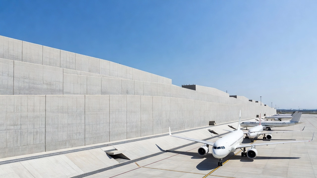
Retaining walls at airports are used to support aircraft aprons, taxiway fills, runway extensions on sloped terrain, access road embankments, drainage channel walls, and security perimeter walls. Airport retaining walls face unique requirements beyond typical transportation retaining walls due to aircraft loading, safety zones, and FOD prevention.
Aircraft loading on retaining walls occurs when walls are located adjacent to aircraft movement areas (taxiways, aprons). Live load surcharge from aircraft landing gear can be substantial — the Boeing 777 main gear load is 145 kN per wheel with tire pressures exceeding 1.5 MPa. Per ICAO Annex 14, Volume I (Aerodrome Design and Operations), retaining walls near operational areas must be designed for these concentrated loads and located behind the runway/taxiway strip safety area. Where walls must be within obstacle limitation surfaces, they require frangible design — the wall must break away or collapse under aircraft impact to minimize damage to the aircraft.
FOD prevention is a critical consideration — any loose stones, concrete fragments, or failed wall elements that could fall onto aircraft movement areas constitute Foreign Object Debris (FOD), a serious aircraft safety hazard. Airport retaining walls must be inspected regularly to identify spalling, loose panels, or drainage stones that could become FOD. FAA Advisory Circular AC 150/5300-13C requires that airport retaining walls in operational areas be designed with positive FOD prevention features including sealed joints, flush connections, and secondary containment for drainage stone.
Drainage at airport retaining walls is particularly critical because water accumulation on adjacent pavements creates hydroplaning hazards and reduces pavement friction. The wall drainage system must discharge water away from aircraft movement areas, typically into the airport stormwater collection system rather than onto adjacent pavements. Frost penetration design is required in cold climates — walls must be designed with frost depth protection to prevent frost heave that could displace wall panels and create pavement elevation irregularities.
ICAO design guidance for airport retaining walls is provided through: ICAO Annex 14 (obstacle limitation surfaces, safety areas); ICAO Aerodrome Design Manual (Doc 9157) Part 3 (Pavements) and Part 6 (Frangibility); and individual national standards including FAA AC 150/5300-13C, FAA AC 150/5320-5D (Drainage Design), and FAA AC 150/5370-10H (Standard Specifications for Construction of Airports).
The most common and cost-effective repair intervention is drainage improvement. Existing clogged weeps are cleaned using water jetting or mechanical rodding, and additional weeps are drilled if spacing is insufficient. Foundation toe drains — perforated pipes in gravel trenches at the wall toe — are installed to intercept water that has already accumulated behind the wall. In severe cases, the wall is retrofit with a new chimney and blanket drain system by excavating behind the wall top and installing geocomposite drainage panels or aggregate drains connected to new weep outlets.
Tieback anchors are post-tensioned ground anchors installed through the existing wall face to provide supplemental lateral support. A hole is drilled through the wall at a 15 to 30 degree downward angle, extending into stable soil or rock behind the failure zone. A high-strength steel tendon (strand or bar) is inserted, the bond length is grouted, and the anchor is tensioned to a proof load (typically 133 percent of design load) then locked off at 100 percent of design load. The anchor head bears on a steel bracket plate or concrete reaction block cast on the existing wall face.
Tieback anchors are effective for stabilizing tilting walls, bulging walls, and landslide repair. They provide immediate load resistance — unlike passive systems that require deformation to mobilize resistance. The FHWA recommends permanent anchors be designed for corrosion protection per PTI requirements with at least two independent barriers between the tendon and the ground.
Soil nail retrofit involves installing passive steel bars through the existing wall face into the retained ground using the same top-down process as new construction. The nails are grouted along their full length and terminated at a shotcrete facing or steel bracket on the existing wall face. Soil nailing is effective for walls where the retained ground conditions are suitable for self-supporting short-term excavations — typically granular soils or stiff clays.
Micropile underpinning transfers wall loads to deeper competent bearing strata through small-diameter (100 to 300 mm) drilled and grouted piles. Micropiles are installed through the existing wall footing or immediately adjacent to the wall, connected to the wall through a grade beam or pile cap. Micropiles are particularly effective for walls that have failed due to foundation bearing capacity insufficiency — the wall continues to settle or tilt because the foundation soil lacks capacity. Micropiles bypass the weak foundation soils and transfer loads to rock or dense sand/gravel strata.
Structural shotcrete is applied to deteriorated concrete wall faces to restore section thickness, protect reinforcement, and provide new structural capacity. The deteriorated concrete is removed by hydrodemolition or chipping to sound concrete. New reinforcement (welded wire mesh or bars) is doweled into the existing wall. Shotcrete is applied in layers to the required thickness (typically 75 to 200 mm). Surface drainage provisions are restored including new weep holes drilled through the shotcrete layer.
Where wall distress is beyond repair — severe reinforcement corrosion, extensive cracking, significant tilting exceeding 5 percent — partial or full reconstruction is required. The approach involves: (1) removing the failed wall sections; (2) stabilizing the retained ground to prevent additional movement during reconstruction — temporary tieback anchors or soil nails may be needed; (3) preparing the foundation — correcting any bearing capacity deficiencies, installing drainage; (4) constructing the new wall — using the same or improved wall type based on failure analysis; and (5) restoring site drainage and surface grading.
Compaction grouting — injection of stiff, low-slump cementitious grout under pressure — fills voids behind the wall and densifies loose backfill. Chemical grouting uses low-viscosity chemical solutions that penetrate fine soil pores and harden to create a cemented soil mass. Grouting is used for void filling behind MSE walls where backfill has eroded, and for ground improvement to increase bearing capacity and reduce settlement. Grouting is typically combined with other stabilization methods and requires careful control to avoid damaging the wall or adjacent structures from excessive grout pressures.
Retaining wall design and inspection in the United States is governed by the following primary documents:
AASHTO LRFD Bridge Design Specifications — Section 11 (Abutments, Piers, and Walls) provides the primary design criteria for all retaining wall types including loads, resistance factors, stability criteria, and serviceability requirements. Section 10 (Foundations) covers foundation design including bearing capacity, settlement, and seismic considerations. Section 3 (Loads) includes lateral earth pressure, surcharge, hydrostatic, and seismic load definitions.
FHWA-NHI-10-024 — Design and Construction of Mechanically Stabilized Earth Walls and Reinforced Soil Slopes — The comprehensive MSE wall design manual covering basic concepts, component selection, internal stability, external stability, seismic design, drainage, and construction specifications. Used as the standard reference for all MSE wall projects on the National Highway System.
FHWA GEC-7 — Soil Nail Walls Design Manual — Design and construction guidance for permanent and temporary soil nail walls including nail spacing, length, grouting, facing design, drainage, and corrosion protection.
FHWA-CFLHD Retaining Wall Inventory and Condition Assessment Guide — The standard protocol for retaining wall inventory creation and condition assessment used by state DOTs for asset management programs. Provides the condition rating scale (0 to 9), inspection checklists, and reporting formats.
FHWA-HI-95-038 — Manual for Design and Construction of Bridge Approach Slopes and Abutments — Design guidance for approach fills, abutment types, settlement control, and the bridge approach bump problem.
AASHTO M 288 — Geotextile Specification for Highway Applications — Classification and specification for geotextiles used in retaining wall drainage, filtration, and separation applications.
AASHTO M 43 — Standard Sizes of Coarse Aggregate — Gradation requirements for drainage aggregate used in chimney drains, blanket drains, and filter layers.
Design life for permanent retaining walls is 75 years per AASHTO LRFD criteria, with 100-year service life specified for major structures and bridge abutments. Minimum factors of safety per AASHTO LRFD (using Allowable Stress Design format): 1.5 against sliding, 2.0 against overturning, 3.0 against bearing capacity failure. Using Load and Resistance Factor Design (LRFD), the corresponding load factors for Earth Pressure (EH) are 1.50 for maximum and 0.90 for minimum, and resistance factors for sliding (φτ) is 0.80 for sand and 0.70 for clay, overturning (φt) is 0.90, and bearing resistance (φb) is 0.45 to 0.55 depending on analysis method.
Seismic design per AASHTO LRFD Section 11 and FHWA seismic design guidelines uses the Mononobe-Okabe method for computing dynamic earth pressures. The seismic coefficient (kh) is taken as 0.5 times the peak ground acceleration (PGA) for walls that can tolerate displacement, and 1.0 times PGA for walls where displacement is limited. Permanent displacement is calculated using the Richards-Elms sliding block method, with allowable displacement typically set at 50 to 200 mm depending on wall type and consequence of failure.
The asset management of retaining walls has become an increasing focus for state DOTs following FHWA initiatives on infrastructure resilience. Many states have implemented retaining wall management programs using the FHWA-CFLHD protocol to inventory walls, assess condition, assign risk priority ratings, and allocate maintenance and replacement budgets. NCHRP Synthesis 365 and NCHRP Project 12-58 have provided additional guidance on retaining wall asset management, condition assessment protocols, and performance prediction models.
TarmacView provides AI-powered infrastructure inspection tools to detect retaining wall distress including cracking, tilting, drainage failure, and facing deterioration from visual data. Automate your wall condition assessments and streamline FHWA-compliant reporting.
Soil nailing is an in-situ ground reinforcement technique where closely spaced steel bars are grouted into a soil slope or excavation face as construction proce...
An abutment is the end support structure of a bridge that retains the approach embankment, transfers superstructure loads to the foundation, and accommodates th...
Geotextiles are permeable synthetic fabrics used in pavement and geotechnical applications for separation (preventing subgrade-aggregate mixing), filtration (co...