Retroreflectivity is the property of a surface to reflect light back toward its source with minimal scattering, achieved through glass beads in pavement markings or microprisms in signs. It is essential for night and low-visibility operations on airfields. Covers measurement via retroreflectometer, specification standards, degradation mechanisms, and inspection compliance.
Retroreflectivity of Pavement Markings and Signs
1. Optical Principle of Retroreflection
Retroreflectivity is an optical phenomenon wherein a surface directs incident light predominantly back toward the originating source, with minimal scattering in other directions. This behavior is fundamentally distinct from diffuse reflection, where light scatters uniformly in all directions, and from specular (mirror-like) reflection, where light reflects at an equal angle to the incident angle. In retroreflection, the surface preferentially returns light along the same axis from which it arrived, making the surface appear bright to an observer located near the light source — a geometry that precisely matches the relationship between a pilot in an aircraft cockpit, the landing lights or headlights, and the pavement markings or signs ahead on the airfield.
The photometric quantity that quantifies retroreflectivity is the coefficient of retroreflected luminance, denoted as RL. The unit of measurement is millicandelas per square meter per lux (mcd/m²/lx). This value expresses the luminance (brightness) of the marking as perceived by the observer, per unit of illuminance falling on the marking from the light source. A higher RL value indicates a brighter, more visible marking under the same lighting conditions.
The optical principle relies on two primary physical mechanisms for engineered retroreflection: refraction and internal reflection within spherical glass beads (used in pavement markings), and total internal reflection within microprismatic structures (used in sign sheeting). Both mechanisms achieve the same fundamental outcome — returning light to its source — but through different optical pathways optimized for their respective applications.
The geometry of retroreflection is defined by two critical angles. The observation angle is the angle between the incident light beam (from headlight to marking) and the reflected light beam (from marking to observer’s eye). In standardized measurement, this is set at 2.29 degrees for pavement markings (EN 1436) and varies for sign sheeting depending on the viewing distance. The entrance angle is the angle between the incident light beam and the perpendicular (normal) to the marking surface. For pavement marking measurement, this is set at 1.05 degrees relative to the road surface plane. These specific angular conditions replicate the real-world geometry of a pilot in an aircraft cockpit looking 30 meters ahead at a marking illuminated by the aircraft’s own lighting system.
2. Glass Bead Retroreflectivity in Pavement Markings
The retroreflectivity of airfield pavement markings is achieved through the controlled application of small, transparent glass beads onto the wet marking material during the application process. These beads, typically ranging from 100 to 1400 micrometers (0.1 to 1.4 mm) in diameter, function as microscopic spherical lenses that collect incoming light from landing lights or headlights, refract it into the bead, reflect it off the back surface of the bead (or the bead-binder interface), and refract it again as it exits back toward the source.
Bead Size and Refractive Index
The optical performance of glass beads depends critically on two material properties: size distribution and refractive index (RI) . Glass beads used in airfield markings typically have a refractive index between 1.5 and 1.9. Standard beads with RI of 1.5 are the most common and provide adequate retroreflectivity for general applications. However, for airport markings where maximum night visibility is required — particularly on high-speed runways and at low-visibility operations — Type III beads (RI ≥ 1.7) and Type IV beads (RI ≥ 1.9) are specified. These higher-index beads produce brighter retroreflection because the greater refractive power focuses incoming light more efficiently onto the rear reflecting surface of the bead.
The size of glass beads is selected based on the marking material type, application method, and desired optical performance. Larger beads (600-1400 µm) generally produce higher initial retroreflectivity because they present a larger optical surface area for light collection. However, smaller beads (100-300 µm) can achieve better packing density and may be more resistant to dislodgement by tire action. Most airfield marking specifications require a graded distribution of bead sizes to optimize both retroreflectivity and durability. The ASTM D1155 standard governs the quality testing of glass beads, including requirements for roundness (minimum 70-80% true spheres), refractive index, size grading, and freedom from foreign material.
Bead Embedment Depth
The depth to which glass beads embed into the marking material is perhaps the single most critical factor determining retroreflectivity performance. Each bead must be partially submerged in the wet marking binder (paint, thermoplastic, or epoxy) such that approximately 50-60% of the bead diameter is exposed above the surface. If beads embed too deeply (over 70% submerged), light cannot enter the bead effectively because the incident angle at the air-to-bead interface is too high, and the bead becomes ineffective. If beads embed too shallowly (less than 40% submerged), they are poorly anchored and will be quickly dislodged by aircraft tires, jet blast, or snowplow operations, resulting in rapid retroreflectivity loss.
The embedment depth is controlled by the drop-on rate (the quantity of beads applied per unit area), the viscosity and thickness of the wet marking film, and the timing of bead application relative to the curing of the marking material. Beads applied too early will sink completely into thin paint films, while beads applied too late will not adhere. Modern self-propelled striping equipment uses precision bead dispensers that synchronize bead drop with paint application speed, ensuring uniform bead distribution and optimal embedment.
Bead Coating and Treatment
To improve adhesion and optical performance, glass beads may receive surface treatments. Silane coupling agents are applied to improve the chemical bond between the glass bead surface and organic marking binders such as epoxy, polyurea, or thermoplastic. This treatment significantly reduces bead loss under traffic wear. Some specialty beads receive moisture-resistant coatings that prevent the formation of a water film over the bead surface, which would otherwise interfere with light refraction and reduce wet retroreflectivity. For applications requiring enhanced wet-night visibility, manufacturers produce “wet-reflective” beads that incorporate optical elements — such as a reflective layer at the bead back or special crystalline structures — designed to function even when submerged in a water film.
3. Microprismatic Retroreflectivity for Sign Sheeting
While pavement markings rely on glass bead technology, airport signs — including mandatory instruction signs (runway holding position), information signs (taxiway direction, location), and runway distance remaining signs — achieve retroreflectivity through microprismatic retroreflective sheeting. This technology uses precisely engineered arrays of microscopic prismatic structures, typically based on the corner cube geometry, to achieve retroreflection through total internal reflection rather than refraction.
Corner Cube Microprism Design
A microprismatic retroreflector consists of an array of corner cube elements — three mutually perpendicular reflective surfaces meeting at a single apex, forming the corner of a cube. When light enters the sheeting from the front, each incident ray encounters one of these corner cubes and is reflected sequentially off all three surfaces. The triple reflection reverses the direction of the light ray, causing it to exit the sheeting along a path parallel to — but opposite from — its entry direction. Because the reflection is achieved through total internal reflection within the prismatic material, no metallic reflective coating is required, and the optical efficiency is exceptionally high.
The density of microprismatic elements in modern sign sheeting is remarkable: high-performance sheeting can contain over 50,000 individual corner cube elements per square centimeter, each precisely molded into the surface of a transparent polymeric film. The prismatic layer is typically made from acrylic resin or polycarbonate, selected for its optical clarity, durability, and UV stability. The sheeting is then laminated to an aluminum sign substrate and covered with a protective transparent top film that contains UV absorbers and provides weather resistance.
ASTM D4956 Sheeting Types for Airfield Signs
The performance classification of retroreflective sheeting for traffic control signs, including airfield signs, is governed by ASTM D4956 Standard Specification for Retroreflective Sheeting for Traffic Control. This standard defines multiple sheeting types based on retroreflective performance, durability, and construction:
For airfield applications, ICAO Annex 14 requires that signs intended for night use shall be retroreflective or illuminated. For non-illuminated signs, Type IX or Type XI microprismatic sheeting is typically specified by FAA Advisory Circular AC 150/5345-44 (Specification for Runway and Taxiway Signs). These high-intensity sheeting types provide the wide observation angles needed for pilots to read signs from various approach angles during taxiing, and they maintain performance across the full range of incident angles encountered in airfield operations.
Glass Bead vs. Microprismatic Comparison
Glass bead reflectors offer omni-directional retroreflection (performance is relatively uniform regardless of the rotation angle of the surface), lower cost, and proven durability in abrasive environments. However, they have lower peak retroreflectivity and narrower effective angular range. Microprismatic sheeting provides 3-5 times higher retroreflectivity, superior performance at wider observation angles, and better thin-edge appearance. The trade-off is higher cost and some vulnerability to angular sensitivity — microprismatic sheeting loses retroreflectivity more rapidly at extreme entrance angles compared to glass bead sheeting. For critical airfield applications where maximum visibility is required — such as runway holding position signs — microprismatic sheeting has become the standard.
4. Measurement of Retroreflectivity
The measurement of retroreflectivity requires specialized instruments called retroreflectometers, which simulate the geometric relationship between a light source, the marking or sign, and the observer. These instruments must conform to strict optical geometries defined by international standards to produce legally valid, reproducible measurement data.
The 30-Meter Measurement Geometry
Both ASTM E1710 (Standard Test Method for Measurement of Retroreflective Pavement Marking Materials) and EN 1436 (Road Marking Materials — Performance Requirements for Road Markings) define the 30-meter geometry as the standard condition for measuring pavement marking retroreflectivity. This geometry simulates a pilot looking 30 meters (approximately 100 feet) ahead at a marking illuminated by the aircraft’s own lights.
Under this geometry, the measurement parameters are:
Observation angle (α) : 2.29° — the angle between the incident light beam and the reflected beam entering the observer’s eye. This corresponds to the vertical separation between a light source mounted at 0.65 m height and an observer eye height of 1.2 m, at a viewing distance of 30 m.
Entrance angle (β) : 1.05° — the angle between the incident light and the pavement surface plane. This represents the slight downward tilt of the light beam relative to the horizontal.
Illuminance on the marking: Standardized to produce a known illumination level at the measurement point.
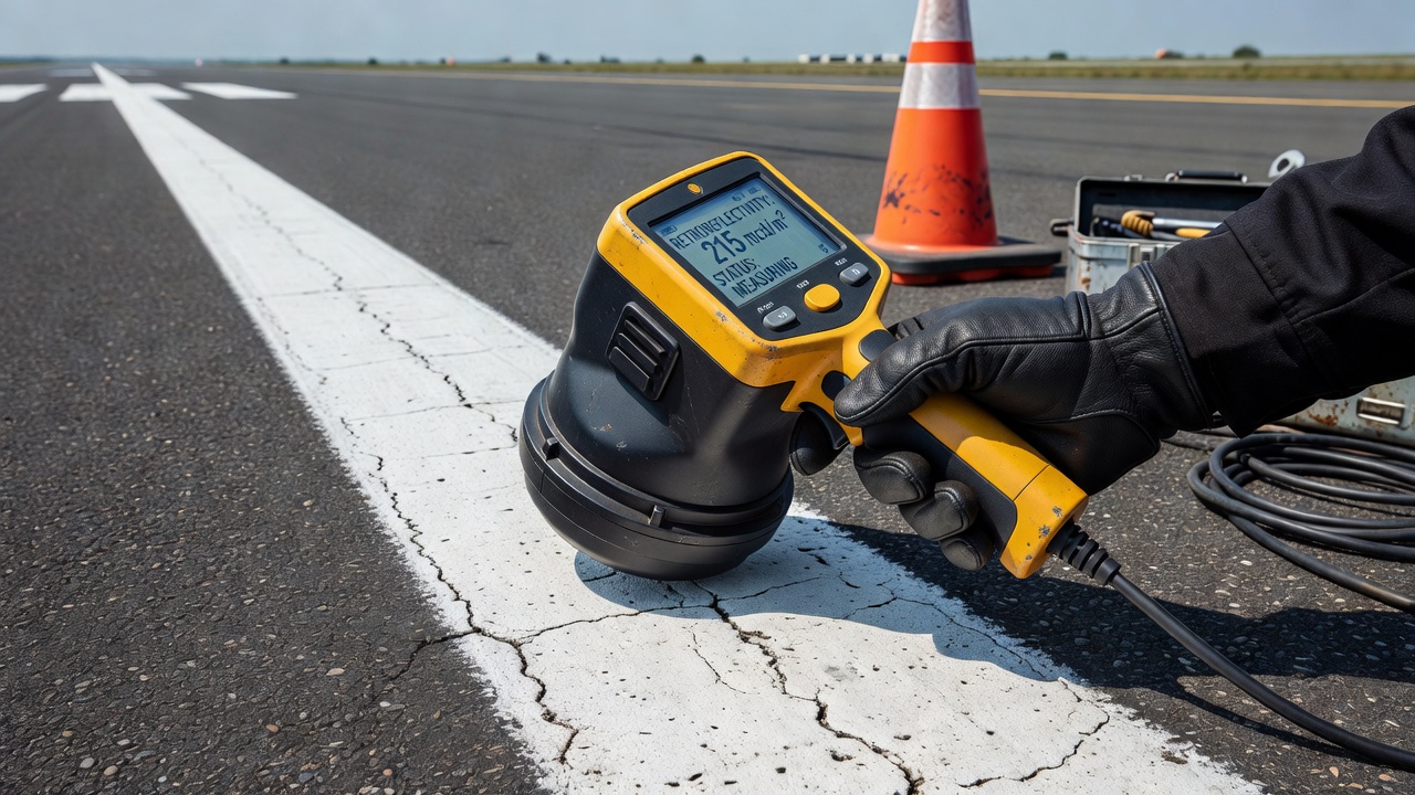
Portable Handheld Retroreflectometers
Handheld retroreflectometers are the primary instruments for static spot-check measurements of pavement markings. These devices are placed directly on the pavement marking surface, and the measurement aperture is aligned with the marking. The instrument houses an internal light source and photodetector arranged to replicate the 30-meter geometry at a compact scale. Within the instrument, fiber optics and precision optics reproduce the correct observation and entrance angles, allowing accurate measurement in a field-portable form factor.
Modern handheld instruments, such as the RoadVista Stripemaster 3 and the QualiRLQD, can measure both the nighttime retroreflection coefficient (RL) and the daytime luminance coefficient under diffuse illumination (Qd) in a single pass. The Qd measurement is important because it quantifies how bright the marking appears under daylight conditions — a marking with good RL but poor Qd may appear washed out during daytime. These instruments also record GPS coordinates of each measurement point, allowing the creation of spatial databases of marking condition.
Measurement procedure per ASTM E1710 requires that:
The measurement surface must be clean and dry (for dry retroreflectivity measurement).
The instrument is placed on the marking and leveled using built-in bubble levels.
A measurement is taken and recorded. Multiple readings (typically 3-5) are averaged for each test location.
The instrument is calibrated before each use using a reference standard plaque with known RL value.
Mobile Retroreflectometry Systems
For network-scale assessment of airfield markings, mobile retroreflectometers mounted on vehicles provide dramatically higher data collection efficiency. These systems, such as the Laserlux G7 and the Sightline Mobi, are front-mounted or roof-mounted on inspection vehicles and take continuous measurements at 400 readings per second while traveling at speeds up to 100 km/h. The instrument projects a laser or light beam onto the pavement ahead of the vehicle at the standard 30-meter geometry and measures the returned light intensity using synchronized detection.
Mobile systems provide several advantages over handheld instruments. They capture complete coverage of every marking on the airfield rather than isolated spot checks, they eliminate traffic control requirements for measurement operations, and they generate comprehensive GIS-mapped datasets showing retroreflectivity variation across the entire airfield. According to Sightline, which has conducted nearly 4 million retroreflectivity scans across US airports, mobile assessment data shows that only 5% of airfield marking data falls below minimum FAA levels, while approximately 31% is marginal and over half is in good or excellent condition. This data demonstrates that targeted maintenance based on actual measurement can save significant costs compared to fixed-interval repainting schedules.
Sign Retroreflectivity Measurement
For airport signs, retroreflectivity is measured using portable retroreflectometers designed for sign sheeting, such as the RoadVista 933 Goniometer System. These instruments measure the coefficient of retroreflection (RA) in units of candela per lux per square meter (cd/lx/m²) , using standardized observation angles of 0.2° and 0.5° and entrance angles of -4° and +30° per ASTM E810 and ASTM D4956. The sign retroreflectometer is placed against the sign face, and a series of measurements are taken at defined points across the sign area to ensure uniform sheeting performance.
5. Retroreflectivity Specifications and Standards
ICAO Annex 14 Standards
The International Civil Aviation Organization (ICAO), through Annex 14 to the Convention on International Civil Aviation, Volume I — Aerodrome Design and Operations, establishes the international baseline for retroreflectivity requirements. ICAO does not prescribe specific numeric RL values in micromoles, but requires that all markings intended for use at night shall be retroreflective. The underlying Standard (Chapter 5, Visual Aids) states that markings must be “conspicuous and of a color that contrasts with the pavement on which they are applied” and must “be retroreflective so as to be visible at night.”
For signs, ICAO Annex 14 requires that “signs shall be retroreflective and/or illuminated.” This applies specifically to mandatory instruction signs (red background with white inscription), information signs (black with yellow inscription for location, yellow with black inscription for direction), and runway distance remaining signs. ICAO also specifies that the retroreflective properties must be maintained throughout the service life of the sign.
FAA Advisory Circulars and 14 CFR Part 139
In the United States, the Federal Aviation Administration (FAA) provides more specific retroreflectivity guidance. 14 CFR Part 139.311(d) requires that certificate holders must properly maintain each marking, sign, or lighting system, including “cleaning, replacing, or repairing any faded, missing, or nonfunctional item.” The FAA has further operationalized this requirement through advisory circulars.
FAA AC 150/5370-10H (P-620) — Standards for Airfield Pavement Marking Materials — defines the minimum retroreflectivity values for newly applied airfield markings. The specification requires:
Initial RL for white markings: minimum 250 mcd/m²/lx
Initial RL for yellow markings: minimum 175 mcd/m²/lx
Daytime luminance Qd for white markings: minimum 130 mcd/m²/lx
Daytime luminance Qd for yellow markings: minimum 100 mcd/m²/lx
These values apply to markings measured using the ASTM E1710 geometry at the time of application. The FAA further specifies that markings must maintain retroreflectivity above minimal levels throughout their service life, and that airports shall have a maintenance program that ensures compliance.
FAA AC 150/5345-44L specifies the retroreflectivity requirements for airfield signs, requiring that sheeting used for non-illuminated signs meet the performance levels of ASTM D4956 Type IX or Type XI. FAA AC 150/5345-39E provides the specification for L-853 Runway and Taxiway Retroreflective Markers — the raised retroreflective markers used in addition to painted markings on some airfields.
European Standard EN 1436
In Europe, EN 1436 — Road Marking Materials — Performance Requirements for Road Markings provides the governing specification. This standard defines a comprehensive classification system for marking performance, including retroreflectivity (RL), luminance (Qd), skid resistance (SRT), and color. For airport markings, national aviation authorities such as EASA adopt EN 1436 with aviation-specific amendments.
EN 1436 defines the following RL classes for dry pavement markings:
Class R0: No requirement (unclassified)
Class R1: RL ≥ 100 mcd/m²/lx (low performance)
Class R2: RL ≥ 150 mcd/m²/lx (minimum for most roads)
Class R3: RL ≥ 200 mcd/m²/lx (standard for high-speed roads)
Class R4: RL ≥ 300 mcd/m²/lx (high performance)
Class R5: RL ≥ 500 mcd/m²/lx (very high performance)
For airfield applications, aviation authorities typically require Class R3 or better for runway markings and Class R2 or better for taxiway markings. EN 1436 also defines wet retroreflectivity classes (RW1 through RW4) for markings tested under continuous water film conditions.
6. Retroreflectivity Degradation Mechanisms
Retroreflectivity is not a permanent property — it degrades progressively over the service life of a marking or sign through several distinct mechanisms. Understanding these degradation pathways is essential for effective maintenance planning.
Glass Bead Loss
The most significant cause of retroreflectivity degradation in pavement markings is bead loss — the physical dislodgement of glass beads from the marking binder. Beads are held in place by the mechanical grip of the surrounding marking material. As aircraft tires roll over markings during taxi, takeoff, and landing, the shear forces exerted on exposed beads gradually work them loose. The rate of bead loss is highest in the wheel path zones of runways and taxiways, where tire contact is concentrated. Research by the University of Washington Washington State Transportation Center (TRAC) has shown that retroreflectivity in heavy-traffic areas can decline by 50-70% in the first six months after application, even as markings in low-traffic areas maintain acceptable levels for 12-24 months.
Snowplow blade contact is a particularly aggressive mechanism on airfields in cold climates. Snowplow blades scraping across marking surfaces can dislodge or fracture large percentages of exposed beads in a single pass. Jet blast from aircraft engines, especially at takeoff power, creates high-velocity exhaust streams that can erode marking surfaces and remove beads from areas behind runway thresholds and at taxiway hold points. The FAA’s Airport Pavement Paint Study (New Hampshire DOT, 2020) found that bead loss and reflectivity are not linearly correlated — markings can retain significant bead populations while still losing retroreflectivity due to surface contamination.
Surface Wear and Abrasion
Beyond bead loss, the marking material itself undergoes abrasive wear from tire action. The marking thickness decreases over time as the binder material is worn away, reducing the number of beads that can be retained. For paint markings applied at 15-20 mils (0.38-0.51 mm) dry film thickness, the usable life is typically 12-24 months before wear reduces the marking to a level where bead retention is compromised. For thermoplastic markings applied at 90-125 mils (2.3-3.2 mm), useful life can extend to 3-5 years. For epoxy or polyurea markings, service life can reach 5-8 years depending on traffic and environmental conditions.
Dirt and Rubber Accumulation
Contamination buildup on marking surfaces is a major factor in retroreflectivity degradation that is often underestimated. Aircraft tires deposit thin layers of rubber on runways, particularly in touchdown zones where rubber build-up from landing aircraft accumulates. This rubber layer, combined with dirt, fuel residue, deicing fluids, and atmospheric deposits, forms a film that coats glass beads and prevents light from entering them. Even beads that remain physically intact become optically ineffective when covered by a contaminant film.
The FAA requires that airports conduct rubber removal on runways when rubber accumulation exceeds specified limits. Rubber removal operations — using high-pressure water blasting or chemical solvents — can restore marking retroreflectivity to near-original levels if the underlying marking material and beads are still intact. Regular cleaning of markings as part of airfield maintenance programs can extend the effective life of markings significantly without the cost of reapplication.
UV Degradation and Binder Aging
Ultraviolet (UV) radiation from sunlight causes photochemical degradation of organic marking binders. The binder material becomes brittle, develops micro-cracks, and loses adhesion to both the underlying pavement and the embedded glass beads. This process accelerates bead loss as the cracked binder can no longer hold beads securely. UV degradation is more severe in high-altitude airports and those in equatorial regions. Additives such as UV stabilizers and HALS (hindered amine light stabilizers) are incorporated into modern marking materials to slow this degradation.
For sign sheeting, UV degradation manifests as yellowing, loss of transparency, and embrittlement of the protective top film. This reduces both the retroreflective performance and the overall appearance of the sign. ASTM D4956 requires accelerated weathering testing (xenon arc per ASTM G155) to qualify sheeting for 3-year, 7-year, 10-year, or 12-year durability ratings depending on the sheeting type.
7. Inspection and Compliance Monitoring
Regulatory Inspection Requirements
Under 14 CFR Part 139, airports serving commercial air carriers must conduct regular inspections of all airfield markings and signs. These inspections are part of the broader airport certification inspection program and are documented in the Airport Certification Manual (ACM). FAA inspectors review marking condition during Part 139 safety inspections, and discrepancies related to faded or non-reflective markings are among the most frequently cited violations.
The FAA has increasingly emphasized objective measurement over subjective visual assessment. Effective December 21, 2018, FAA AC 150/5370-10H P-620 formalized the minimum retroreflectivity requirements for airfield markings, moving beyond the previously subjective “clearly visible” standard. Airports are now expected to use retroreflectometers to quantify marking condition and document compliance.
Inspection Intervals and Methodology
Best practice for airfield marking retroreflectivity inspection follows a tiered approach:
Daily visual inspection: Airfield personnel conduct visual checks of marking condition during daily airfield safety inspections, noting any obviously faded, worn, or contaminated areas.
Quarterly quantitative assessment: Markings are measured using a portable retroreflectometer at representative locations — typically the midpoint and ends of each runway marking zone (threshold, centerline, touchdown zone, and aiming point), plus each taxiway centerline and hold position marking.
Annual comprehensive assessment: A full airfield marking assessment using mobile retroreflectometry, covering 100% of runway and taxiway markings, generating a GIS-based compliance map.
Data Management and Compliance Documentation
Modern retroreflectivity inspection programs generate large datasets. Each measurement point is geotagged with GPS coordinates, time-stamped, and recorded with the measured RL value, temperature, and marking type. This data is imported into an asset management system (AMS) that tracks retroreflectivity trends over time, enabling predictive maintenance decisions. The data also serves as documented evidence of compliance during FAA Part 139 inspections.
Sightline’s airfield marking assessment service, which has collected data at numerous US airports, reports that airports using measurement-based maintenance programs reduce marking expenditures by an average of 40-50% compared to fixed-interval repainting, because they only repaint markings that actually require restoration rather than following arbitrary calendar schedules.
8. Dry vs. Wet Retroreflectivity
The Challenge of Wet Conditions
Wet retroreflectivity — the ability of a marking to remain visible when covered by a continuous water film — represents a fundamentally different and more challenging performance requirement than dry retroreflectivity. When water covers a standard pavement marking, it fills the gap between the glass beads and creates a smooth refractive interface that eliminates the retroreflective effect. Light from headlights enters the water film and passes over the beads without being focused back toward the source. This effect is so pronounced that wet retroreflectivity of standard markings can drop to 10-20% of dry values — a marking that measures 300 mcd/m²/lx when dry may measure only 30-50 mcd/m²/lx when wet.
Wet-Reflective Marking Technology
Specialized wet-reflective markings address this problem through several design approaches:
Higher refractive index beads (RI ≥ 1.9) are less susceptible to water film interference because the greater refractive power can overcome the optical disruption caused by the water layer. Structured markings incorporate surface textures — such as raised profiles or ribs — that create elevation differences sufficient to protrude beads above the water film thickness. Multi-layer systems use a base layer of standard beads with a top layer of larger, higher-index beads that extend above the maximum water film thickness.
Studies by the Federal Highway Administration (FHWA) have shown that premium wet-reflective markings can maintain RL values of 150-250 mcd/m²/lx under wet conditions, compared to 30-50 mcd/m²/lx for standard markings. For airfield applications where operations continue in rain and low-visibility conditions, wet-reflective markings are increasingly specified for runways, particularly at airports conducting Category II and Category III low-visibility operations.
Measurement of Wet Retroreflectivity
EN 1436 specifies the method for wet retroreflectivity measurement. A continuous water film is applied to the marking surface at a controlled rate (typically 1 mm/min) to achieve complete coverage. The retroreflectometer measures RL while the water film is maintained. The measurement must be completed within a defined time window to ensure consistent water film conditions. The wet retroreflectivity class (RL-wet) determined by this method provides a performance rating under simulated rain conditions.
9. AI-Based Retroreflectivity Estimation
Computer Vision-Assisted Assessment
Recent advances in computer vision and deep learning are enabling new approaches to retroreflectivity assessment that complement traditional retroreflectometer measurements. Researchers at multiple institutions — including the University of Washington, Texas A&M Transportation Institute, and the Turner-Fairbank Highway Research Center — have developed methods for estimating retroreflectivity from high-resolution pavement imagery captured by airfield inspection vehicles.
These AI-based systems work by training convolutional neural networks (CNNs) on large datasets of pavement marking images with corresponding retroreflectometer measurements. The networks learn to identify visual features correlated with retroreflectivity — including color saturation, surface texture, bead visibility, and wear patterns — and then predict RL values from new images. The best-performing models have demonstrated correlation coefficients (R²) of 0.85-0.93 between predicted and measured RL values, approaching the accuracy of handheld retroreflectometers.
Mobile Phone-Based Systems
Lower-cost approaches using smartphone cameras and machine learning have been developed for rapid screening. These systems use the phone’s flash as a light source and the camera as a detector, with the fixed geometry between flash and camera lens approximating retroreflectometer conditions when the phone is held at a defined distance and angle from the marking. While less accurate than professional retroreflectometers, these systems can provide useful screening data for prioritizing more detailed inspections.
AI for Predictive Maintenance
The most impactful application of AI in retroreflectivity management is predictive modeling of degradation curves. By training machine learning models on historical retroreflectivity data combined with traffic counts, environmental data (temperature, precipitation, UV exposure), and marking material specifications, AI systems can forecast how retroreflectivity will decline over time for specific marking types at specific locations. This enables airports to move from reactive maintenance (responding to failures) to predictive maintenance (scheduling remarking before thresholds are breached, but not prematurely).
The TRAC study at the University of Washington found that while degradation curves show significant variability due to application quality differences, environmental conditions, and measurement uncertainty, AI models incorporating these factors can reduce the uncertainty band by 40-50% compared to simple time-based predictions. The Transportation Research Board (TRB) has identified AI-based pavement marking condition assessment as a priority research area (RES2025-09).
10. Remarking Triggers and Threshold-Based Maintenance
Establishing Action Thresholds
Effective retroreflectivity management requires clear action thresholds — the RL values below which marking restoration is triggered. These thresholds are established based on regulatory requirements, operational needs, and economic optimization. For airfield markings, typical thresholds are:
Marking Type
Action Level (RL, mcd/m²/lx)
Priority
Runway centerline (white)
< 150
High
Runway threshold markings (white)
< 150
High
Runway touchdown zone (white)
< 120
Medium
Taxiway centerline (yellow)
< 100
Medium
Hold position markings (yellow)
< 100
High
Apron markings
< 80
Low
These thresholds are typically set at approximately 50-60% of the initial minimum specification values, representing the level at which pilot visibility becomes significantly degraded.
Types of Remarking Triggers
Remarking decisions are triggered by one or more of the following conditions:
Threshold-based triggers occur when measured retroreflectivity drops below the defined action level at any point on the marking. This approach ensures markings never become dangerously under-performing anywhere in the network.
Age-based triggers initiate remarking when markings reach a predetermined age limit, even if retroreflectivity measurements have not yet fallen below thresholds. This is a fallback for airports without measurement programs.
Interval-based maintenance follows a fixed calendar schedule regardless of condition. While simple to administer, this approach typically results in over-maintenance (markings repainted when still serviceable) or under-maintenance (markings failing before scheduled replacement).
Risk-based triggers incorporate consequence of failure into the threshold definition. Markings on high-speed runways used for low-visibility operations have lower action thresholds than markings on low-traffic taxiways, reflecting the higher safety consequence of marking failure in critical areas.
Cost Optimization Through Assessment-First Strategies
Industry data consistently shows that airports using assessment-first maintenance strategies — measuring retroreflectivity before deciding which markings to repaint — achieve substantial cost savings. Sightline’s analysis of nearly 4 million retroreflectivity scans at US airports found that only 5% of marking data falls below minimum FAA levels, meaning that 95% of markings are at least minimally compliant. Another 31% of data is in the marginal range (above the minimum but approaching it), and the remainder is in good or excellent condition.
In practice, this means that an airport that repaints all markings on a fixed 2-year schedule is likely repainting 60-70% of markings prematurely — spending money on markings that still have substantial remaining service life. An assessment-first approach would identify the 30-40% of markings that genuinely need restoration, reducing annual marking expenditures by 40-50% while actually improving safety by ensuring that the markings that need attention receive it promptly.
Nashville International Airport (BNA) documented savings of $350,000 per year by implementing an assessment-first approach to airfield marking maintenance, repainting only the markings that fell below retroreflectivity thresholds rather than following a fixed schedule. Charlotte Douglas International Airport reported similarly significant reductions in marking costs combined with measurable improvements in marking condition consistency.
Lifecycle Cost Modeling
Lifecycle cost analysis for airfield markings considers not just the cost of application but also the time-value of retroreflectivity degradation. A marking material with higher initial cost but slower degradation rate may offer lower lifecycle cost than a cheaper material that requires more frequent reapplication. For example, standard waterborne paint at $0.50 per linear foot with 18-month service life has a lifecycle cost of $0.33/ft/year. Epoxy marking at $1.50 per linear foot with 7-year service life has a lifecycle cost of $0.21/ft/year — a 36% reduction despite higher upfront cost. When the cost of traffic control, application mobilization, and downtime during repainting are included, the premium materials become even more cost-effective.
Summary
Retroreflectivity is the enabling technology that makes airfield pavement markings and signs visible at night and in low-visibility conditions. Through the optical principles of spherical glass beads in markings and microprismatic structures in signs, incident light from aircraft landing lights and headlights is returned to the pilot’s eyes, providing the critical visual cues needed for safe ground navigation. The property is quantified as the coefficient of retroreflected luminance (RL) in mcd/m²/lx, measured using retroreflectometers conforming to the 30-meter geometry of ASTM E1710 and EN 1436.
ICAO Annex 14 and FAA regulations establish compliance requirements for retroreflectivity, with specifications for minimum initial values (250 mcd/m²/lx for white, 175 mcd/m²/lx for yellow) and maintenance programs to ensure markings remain above threshold levels throughout their service life. Degradation occurs through bead loss, surface wear, contamination, and UV aging — each of which can be managed through appropriate inspection and maintenance programs.
Modern best practice for retroreflectivity management includes mobile retroreflectometry for network-scale assessment, AI-based condition prediction for proactive maintenance planning, and assessment-first strategies that target limited maintenance resources to the markings that genuinely need restoration. This approach measurably improves safety outcomes while reducing maintenance costs by 40-50% compared to fixed-interval repainting schedules.
Related terms: Pavement marking, Runway marking, Taxiway marking, Sign sheeting, Glass beads, Retroreflective marker, Visual aids, Night operations, Low-visibility operations, Airport inspection, FAA Part 139 compliance, ICAO Annex 14.
Frequently Asked Questions
Retroreflectivity is the ability of a pavement marking to reflect light from an aircraft's landing lights or headlights back toward the pilot, making the marking appear bright at night. This is achieved by embedding tiny glass beads into the marking material. The beads act as optical lenses that collect incoming light and redirect it back to the source. The coefficient of retroreflected luminance (RL) quantifies this property in millicandelas per square meter per lux (mcd/m²/lx). Higher RL values mean brighter, more visible markings at night.
Retroreflectivity is measured using a retroreflectometer, an instrument that simulates the geometry of a pilot in an aircraft cockpit viewing a marking 30 meters ahead. The measurement follows the 30-meter geometry defined by ASTM E1710 and EN 1436, with an observation angle of 2.29° and an entrance angle of 1.05°. The instrument emits a controlled light beam onto the marking and measures the amount of light returned to the detector. Measurements can be taken with handheld devices for spot-checking or with mobile systems mounted on vehicles for continuous, high-speed network surveys at speeds up to 100 km/h.
ICAO Annex 14 requires that all runway and taxiway markings intended for night use be retroreflective. In the United States, FAA Advisory Circular AC 150/5370-10H (P-620) defines minimum retroreflectivity levels for airfield pavement markings, typically requiring white markings to maintain RL values above 250 mcd/m²/lx and yellow markings above 175 mcd/m²/lx initially. For signs, ICAO mandates that all mandatory instruction signs and information signs intended for night use be retroreflective or illuminated. FAA AC 150/5345-44 specifies that airfield signs must meet ASTM D4956 retroreflective sheeting requirements, typically Type III, IV, IX, or XI depending on the application.
Retroreflectivity degrades over time due to several mechanisms. Glass bead loss occurs when the binder holding beads in the marking material erodes from tire action, snowplow blades, or jet blast. Surface wear from aircraft tires and ground vehicles abrades both the marking material and exposed beads. Dirt and rubber accumulation from tire deposits obscures beads and reduces light transmission. Ultraviolet (UV) radiation from sunlight causes the binder material to become brittle and crack, leading to bead loss. The degradation rate depends on traffic volume, environmental conditions, marking material type, and the quality of the initial application.
Dry retroreflectivity is measured when the pavement marking surface is clean and dry, representing optimal night visibility. Wet retroreflectivity is measured when a continuous water film covers the marking, simulating rain conditions. When water covers standard pavement markings, it forms a film over the glass beads that prevents light from entering them properly, drastically reducing retroreflectivity — often by 80-90% compared to dry conditions. Wet-reflective markings use specially designed beads with higher refractive indices or optical structures that protrude above the water film, maintaining retroreflectivity even in rain. These are increasingly specified for high-speed runways and low-visibility operations.
Ensure Your Airfield Markings Are Compliant
Retroreflectivity compliance is essential for safe night and low-visibility operations. Our team can help you assess, measure, and maintain your airfield pavement markings and signs to meet ICAO and FAA standards. Contact us for a consultation or schedule a demo of our advanced inspection solutions.
Specular Reflection (Mirror-like Reflection) in Optics
Specular reflection is the mirror-like reflection of light from an optically smooth surface, obeying the law of reflection and enabling clear image formation. I...
Reflectance is the ratio of reflected to incident radiant flux on a surface, crucial in optics, remote sensing, materials science, and aviation for understandin...
A retroreflector is an optical device that reflects light or electromagnetic waves back toward their source, regardless of the incident angle, within a design r...
7 min read
Optics
Road Safety
+3
Cookie Consent We use cookies to enhance your browsing experience and analyze our traffic. See our privacy policy.