Bridge Scour — Assessment and Monitoring
Scour is the erosion or removal of streambed or bank material around bridge foundations (piers and abutments) due to flowing water, the leading cause of bridge ...
31 min read
Bridges
Bridge Inspection
+4
Riprap is a layer of loose, angular stone or concrete blocks placed around bridge piers, abutments, and channel banks to armor the streambed against scour erosion. FHWA HEC-23 and HEC-18 provide design procedures for riprap size, gradation, layer thickness, and filter requirements. Riprap condition — displacement, settlement, weathering, undercutting — must be regularly inspected under NBIS/SNBI protocols using B.C.10 Channel Protection Condition Rating. Covers riprap design methodology, placement methods, inspection criteria, common failure modes, and alternative scour countermeasures including articulated concrete blocks, gabion mattresses, grout bags, and partially grouted riprap.
{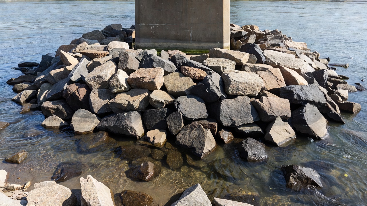
Riprap (also spelled rip rap or rock riprap) is a permanent, engineered layer of loose, angular stone or precast concrete armor units placed on streambeds, riverbanks, or around bridge foundations to protect against erosion and scour caused by flowing water. The term originates from the riprapping or rapping sound of stones being placed. In hydraulic engineering, riprap is formally defined as a sloping protective layer of large, angular, durable stone designed to resist the hydrodynamic forces of flow, waves, and ice.
The primary purpose of riprap around bridge structures is to armor the streambed against local scour — the removal of sediment from around piers and abutments by the horseshoe vortex and downflow that develop at the upstream face of a pier obstruction. Scour is the leading cause of bridge failure in the United States, responsible for more than 60 percent of all bridge collapses according to FHWA data. The catastrophic failure of the Schoharie Creek Bridge in New York on April 5, 1987, which cost 10 lives, was attributed directly to inadequate riprap protection around bridge piers. The National Transportation Safety Board (NTSB) found that over a period from 1953 to 1987, much of the riprap was removed by high flows, and the New York State Thruway Authority had failed to maintain adequate riprap. This event triggered a fundamental shift in how riprap is designed, inspected, and maintained nationwide.
Riprap is the most widely used scour countermeasure for bridges in the United States due to its simplicity, cost-effectiveness, availability, and proven performance record. It functions through several mechanisms: (1) the weight and mass of individual stones resist direct hydraulic lift and drag forces; (2) angular stone shapes create interlocking friction that distributes loads across the layer; (3) the porous nature of the layer dissipates flow energy and reduces near-bed velocities; and (4) the flexible blanket conforms to minor bed deformations without losing integrity, exhibiting what researchers call a “self-healing” capability where displaced stones rearrange to form a new armor layer.
Riprap is applied at bridge piers, abutments, approach embankments, culvert outlets, headwalls, wingwalls, and channel banks adjacent to bridge structures. The FHWA Hydraulic Engineering Circular No. 23 (HEC-23), Bridge Scour and Stream Instability Countermeasures: Experience, Selection, and Design Guidance, Third Edition, is the primary design reference for riprap in the United States. Supplementing HEC-23 are FHWA HEC-18 (Evaluating Scour at Bridges, Fifth Edition) and NCHRP Report 593 (Countermeasures to Protect Bridge Piers from Scour, 2007), which provide the most current sizing equations and performance data.
{{
Riprap design is a multi-parameter engineering process governed by hydraulic conditions, geometric constraints, material properties, and economic considerations. The design methodology is detailed in FHWA HEC-23 Design Guideline 11 (Riprap) and NCHRP Report 593 Appendix C.
The fundamental design parameter for riprap is the median stone diameter D50 — the stone size for which 50 percent of the material by weight is smaller. D50 is determined from the approach flow velocity, flow depth, pier geometry, and channel characteristics. The HEC-23 pier riprap sizing procedure uses the following relationship:
Vdes = K1 × K2 × Vavg
where Vdes is the design velocity at the pier, K1 is the pier shape factor (1.5 for round-nose piers, 1.7 for square-edge piers), K2 is the pier location factor in the channel (ranging from 0.9 near the bank in straight reaches to 1.7 at the main current around a sharp bend), and Vavg is the average approach velocity upstream of the bridge.
The required D50 is then computed using the Izbash formula:
D50 = Vdes² / (2g (SG - 1))
where g is gravitational acceleration and SG is the specific gravity of the stone (typically 2.60 to 2.75 for granite). For typical bridge pier applications, D50 values range from 0.3 m (12 inches) to 1.2 m (48 inches), with the largest requirements occurring at piers in high-velocity, narrow channels with square-nose geometry.
Alternative sizing methods include the Shields parameter approach for bed shear stress and the Parola stability analysis, which accounts for three-dimensional flow effects, pressure fluctuations, and seepage gradients within the streambed. NCHRP Report 593 validated the HEC-23 pier riprap sizing procedure through laboratory testing at prototype scale and confirmed its adequacy for D50/pier-width ratios up to 0.15, noting that the equations become conservative at higher ratios.
Riprap gradation refers to the distribution of stone sizes within the layer. Well-graded riprap contains a range of sizes that fill the voids between larger stones, creating a dense, interlocking matrix. The standard FHWA gradation criteria require:
| Parameter | Requirement |
|---|---|
| D50 (median size) | Per design calculation |
| D85/D15 (uniformity) | 1.5 to 2.5 |
| D100 (maximum size) | ≤ 1.5 × D50 |
| D15 (minimum size) | ≥ 0.15 × D50 |
| Percent passing D50 | 30–70% |
| Maximum void ratio | 40% |
Well-graded riprap significantly outperforms uniform-sized riprap. A mix where large stones form the structural matrix and smaller stones fill the interstices produces a heavier, more stable mass with lower porosity. This reduces flow penetration into the layer and minimizes winnowing potential — the erosion of finer bed material through voids between stones. The D85/D15 uniformity coefficient must be controlled: too narrow a gradation increases permeability and winnowing risk; too wide a gradation can result in washout of the finer fraction.
The minimum riprap layer thickness is specified as 1.5 times the D50 or the diameter of the D100 (largest stone), whichever is greater, and never less than 350 mm (14 inches). For bridge pier applications, a minimum thickness of 2.0 times D50 is commonly specified to account for the severe turbulence and horseshoe vortex at piers.
Layer thickness serves multiple functions: (1) it ensures that the largest stones are placed in a single layer without protrusion; (2) thicker layers provide sacrificial stone that can be lost to scour without exposing the underlying filter; (3) additional thickness helps prevent winnowing in the absence of a filter, as demonstrated by Chiew (1995) where thick riprap layers sustained partial breakup with a self-healing rearmoring capability; and (4) thicker sections accommodate construction tolerances and stone interlocking.
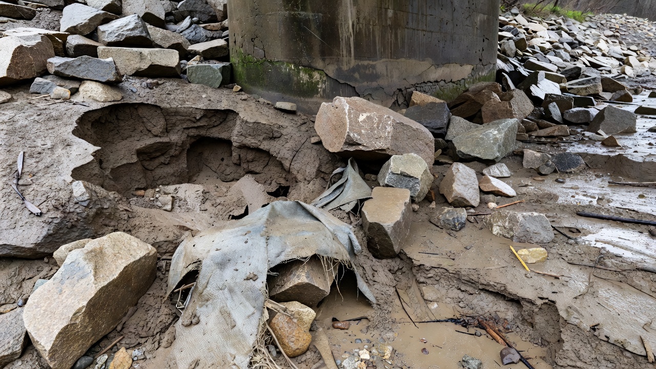
A filter layer is an essential component of any riprap system. Without it, hydraulic gradients caused by flow pressure differentials drive soil piping — the migration of fine soil particles through the voids between riprap stones. As waves and currents impact the riprap, oscillatory pressure gradients pull soil particles out through the interstices, progressively hollowing out the space beneath the armor. This process, known internally as a “translational slide,” leads to sudden collapse of the riprap layer.
Two filter types are used:
Geotextile filter fabric — A woven or non-woven synthetic textile placed directly on the prepared subgrade before riprap placement. The fabric must have an Apparent Opening Size (AOS) small enough to retain the base soil particles (typically AOS No. 70 to No. 100 sieve) while maintaining sufficient permeability to relieve hydrostatic pressure without clogging. The geotextile must extend fully beneath the riprap layer and be securely sealed against the pier face to prevent material loss at the structure-stone interface. FHWA testing by Parker et al. (1998) demonstrated that geotextile extending two-thirds of the distance to the periphery of the riprap produced the best performance; full coverage to the edge sometimes promoted edge failure as the fabric was exposed and torn.
Granular stone filter — A layer of smaller, clean, durable stone placed between the base soil and the riprap armor. The filter D50 must be designed to retain the underlying soil while remaining hydraulically permeable. Minimum granular filter thickness is 150 mm (6 inches) or three times the filter D50, whichever is greater. Granular filters are preferred in environments with high bedload transport (dune-type bedforms) where geotextile may be abraded or torn by moving sediment.
The lateral extent of riprap around a pier must cover the zone of influence of the horseshoe vortex. Per HEC-23 and confirmed by Bertoldi et al. (1996), the riprap should extend at least two pier widths laterally from the pier face in all directions. For wall piers or pile bents skewed to the flow, the extent is further increased by a skew factor Ka based on pier length, width, and skew angle.
Vertically, riprap should be placed flush with the streambed for pier protection and extended from the bottom of the footing up to the ambient bed level unless design scour depths exceed the layer thickness, in which case the riprap extends below the maximum expected scour depth. The toe of the riprap at the layer edge must be keyed into the streambed to prevent undermining and edge failure propagation.
{{
Riprap placement must be executed with care to achieve the designed performance. Three primary placement methods are recognized:
Dumped placement — The most common method for subaqueous placement. Stone is dumped from trucks, barges, or cranes directly onto the prepared filter layer. The stone is dumped in controlled lifts to prevent segregation of the gradation and damage to the underlying geotextile. Drop heights must be limited to prevent impact damage to filter fabrics — typically less than 1.5 m (5 ft) above the placement surface. Dumped riprap tends to settle and rearrange under hydraulic action, eventually achieving a stable configuration.
Individual stone placement — Used where precise grading or thickness control is required, such as around pier noses or abutment corners. Stones are individually positioned by excavator bucket or crane to achieve tight interlocking against the structure face. This method produces the densest, most stable configuration but is significantly more labor-intensive and costly.
Hand-placed riprap — Used for architectural slopes or where access is restricted. Stones are hand-positioned to achieve uniform appearance and maximum interlock. Hand placement is typically specified for visible slopes near bridge abutments or in park settings where aesthetics are a consideration.
Construction considerations include: (1) verifying that the geotextile is continuous and free of tears or folds; (2) ensuring no stones larger than D100 are included in the mix; (3) achieving the specified layer thickness across the full extent; (4) keying the riprap toe to prevent undermining; (5) forming a smooth transition at the edge of the riprap layer rather than an abrupt vertical face; and (6) performing a post-construction survey to document as-built conditions as a baseline for future inspections.
Riprap condition assessment is a mandatory element of the National Bridge Inspection Standards (NBIS) biennial bridge inspection program in the United States. Under the 2022 FHWA Specifications for the National Bridge Inventory (SNBI), riprap is evaluated under Item B.C.10 — Channel Protection Condition Rating.
Bridge inspectors evaluate the following riprap deficiencies during routine inspection:
Displacement — Stones that have moved from their original position, either individually or as a group. Displacement is the most common riprap defect and the primary indicator of incipient failure. Causes include high-velocity flows, ice action, debris impact, vandalism, and settlement of the underlying bed. Displacement is measured by the distance stones have moved from the designed position; stones displaced by more than one stone diameter are typically considered significant.
Undermining — Erosion of the bed material at the edge or toe of the riprap layer, causing a loss of support that leads to progressive edge failure. Undermining is identified by a visible gap between the riprap edge and the natural streambed, slumping of edge stones, or a scour hole adjacent to the riprap toe.
Settlement — Vertical downward movement of the riprap surface due to compaction, loss of underlying filter or soil support, or consolidation of the subgrade. Settlement is measured as the difference from the as-built or design elevation. Significant settlement reduces the effective thickness of protection and may expose the filter layer at the original design elevation.
Weathering and Deterioration — Physical or chemical degradation of riprap stones. Weathering includes cracking, spalling, scaling, exfoliation, and rounding from abrasion. Stone quality is assessed by specific gravity (minimum 2.5), absorption (maximum 2 percent), and freeze-thaw durability. Stones that have degraded to less than 50 percent of their original mass or that break under light hammer blows are considered failed.
Vegetation Growth — Woody vegetation, trees, and large shrubs growing through the riprap layer. Root systems displace stones, create voids, and provide pathways for soil piping. While some grass and small plants can add stability, woody vegetation with root diameters exceeding 25 mm (1 inch) within the riprap layer is considered a defect. Vegetation also obstructs visual inspection of stone condition and displacement.
Filter Fabric Exposure — Geotextile visible at the riprap surface due to stone displacement, settlement, or inadequate coverage. Exposed fabric is subject to ultraviolet degradation (typically within 6 months of exposure), abrasion by transported sediment, and tearing by debris impact. Any visible fabric exposure is a defect requiring prompt repair.
Riprap inspection relies primarily on visual observation from the bridge deck, from the channel banks, and — where depths permit — from wading or boat-based inspection. The inspector records the presence, extent, and severity of each defect type across the riprap installation. Underwater inspection may be required where riprap extends below the water surface; this is typically conducted by divers or using underwater cameras and sonar.
Key inspection actions include: (1) comparing current riprap condition to as-built records and previous inspection documentation; (2) measuring displacement, undermining depth, and settlement using graduated rods, tapes, or laser rangefinders; (3) assessing stone soundness by hammer testing exposed stones above the waterline; (4) documenting vegetation type, density, and root size; (5) recording the percentage of filter fabric exposure; and (6) noting any changes in channel alignment, aggradation, or degradation that may affect riprap performance.
Scour vulnerability classification (A/B/C/D/U per FHWA) is updated based on riprap condition findings. Bridges with riprap in poor condition and high flow exposure are classified as Scour Critical (U) , requiring a Plan of Action (POA) per NBIS requirements.
Under the FHWA SNBI, Item B.C.10 — Channel Protection Condition Rating evaluates riprap and other channel protection countermeasures on a 0-to-9 numerical scale:
| Code | Condition | Description |
|---|---|---|
| N | Not Applicable | No channel protection exists or bridge does not cross water |
| 9 | Excellent | Isolated inherent defects only |
| 8 | Very Good | Some inherent defects |
| 7 | Good | Some minor defects |
| 6 | Satisfactory | Widespread minor or isolated moderate defects |
| 5 | Fair | Some moderate defects; bridge and approach roadway not threatened |
| 4 | Poor | Widespread moderate or isolated major defects; bridge/approach threatened |
| 3 | Serious | Major defects; bridge or approach seriously threatened; monitoring or load restriction needed |
| 2 | Critical | Major defects; severely threatened; frequent monitoring and corrective action needed |
| 1 | Imminent Failure | Bridge closed due to channel condition |
| 0 | Failed | Beyond corrective action; bridge replacement required |
Defect severity definitions per SNBI: Minor — damage initiated but not yet significant; Moderate — damage significant but strength/performance not affected; Major — strength and/or performance affected; Inherent — characteristic of material, not damage.
Defect extent definitions: Isolated — one or a few concentrated locations; Some — more than isolated, less than widespread; Widespread — present in many separate areas.
Riprap rated 4 (Poor) or lower requires more frequent monitoring, typically annually or after each significant flood event (>2-year recurrence interval). Riprap rated 3 (Serious) or lower may require load restrictions, corrective action, or bridge closure depending on the threat level to the structure. The B.C.09 Channel Condition Rating (which evaluates the natural channel, not the protection) is coded separately and can be affected by aggradation, degradation, debris, bank erosion, and channel migration.
Research by Chiew (1995), Lim and Chiew (1996), and Melville et al. (2006) has identified five distinct riprap failure modes:
Shear Failure — The riprap stones are entrained by the flow because they are too small or too light to resist the downflow and horseshoe vortex forces generated at the pier. Shear failure occurs when the applied hydraulic shear stress exceeds the critical shear stress of the stones. The condition is exacerbated by high flow velocities, narrow pier shapes that concentrate flow, and steep approach angles. Prevention requires adequate D50 sizing using the HEC-23 procedure.
Winnowing Failure — The finer underlying bed material is eroded through the voids or interstices between riprap stones. This occurs when the riprap gradation is too open (high void ratio) or the riprap layer is too thin to provide a sufficient hydraulic gradient barrier. Winnowing can occur even when the stones themselves are stable and adequately sized. Prevention requires a properly designed filter layer (geotextile or granular) and sufficient riprap layer thickness.
Edge Failure — Scouring at the periphery of the riprap layer where it meets the natural streambed. The contrast between the rough, erosion-resistant riprap and the erodible natural bed creates a localized scour hole at the interface. This scour undermines the edge stones, which then roll into the scour hole, exposing additional edge stones to the same process. Edge failure propagates inward progressively. Prevention requires adequate lateral extent (minimum two pier widths), toe keying, and periodic edge stone replacement.
Bedform-Induced Failure (Embedment) — Under live-bed conditions, migrating bedforms (dunes and ripples) pass the pier, causing the riprap layer to settle and degrade as the bed level fluctuates. When the trough of a dune passes, the riprap stones lose support and settle downward. This is the dominant failure mode under live-bed conditions and can cause riprap to degrade by 0.2 to 0.4 times the flow depth. The riprap layer can embed entirely into the bed sediment, losing its protective function. Prevention requires placing the riprap deeper than the expected dune trough amplitude — the maximum bedform trough depth below ambient level is approximately 0.2 times the depth of flow (Karim 1999, van Rijn 1984).
Total Disintegration — The complete breakup and dispersal of the riprap layer, typically resulting from a combination of the above modes acting in sequence. Once initiated, failure accelerates exponentially as displaced stones increase flow turbulence and expose adjacent stones. Research by Lim and Chiew showed that total disintegration occurs when the applied hydraulic power exceeds the self-healing ability of the riprap layer.
The Schoharie Creek Bridge failure demonstrates all failure modes in sequence: (1) progressive displacement of riprap stones by repeated high flows over 34 years (shear and edge failure); (2) winnowing of the glacial till foundation material through the voids in the remaining riprap; (3) undermining of the riprap at the pier edge; and (4) eventual collapse of the pier when the spread footing lost bearing support from the eroded foundation soils.
When riprap is not feasible — due to excessive stone size requirements, unavailability of quality stone, difficult placement conditions, or environmental constraints — alternative scour countermeasures are available:
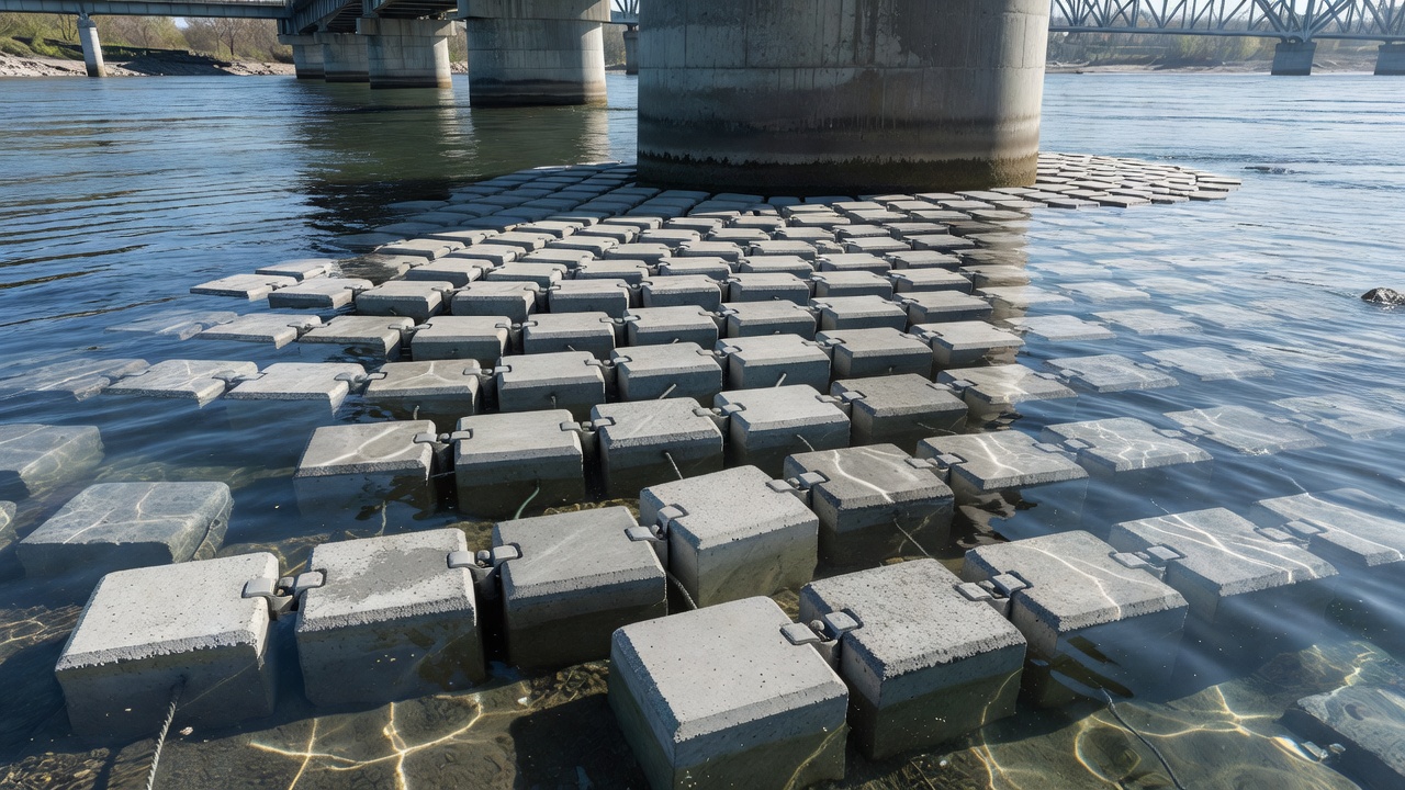
ACBs are preformed concrete blocks interconnected by cables or geometric interlock, forming a flexible mat that conforms to bed movements while maintaining continuous protective cover. ACB design follows HEC-23 Design Guideline 16 using a Factor of Safety (FS) method based on moment balance analysis:
SFT = SFB × XC × XM
where SFT is the target factor of safety, SFB is the base factor of safety (1.2–2.0 depending on application), XC is the consequence of failure multiplier (1.0–2.0), and XM is the hydraulic model uncertainty multiplier (1.0–2.0). A minimum FS of 1.2 is used for revetment; 1.5–1.7 for bridge piers and abutments; and 1.8–2.0 for overtopping spillways.
ACBs offer advantages over riprap: (1) uniform block thickness ensures consistent coverage; (2) cable interconnection prevents individual block displacement; (3) open-cell designs allow vegetation for aesthetic and ecological integration; (4) quantified design safety factor; and (5) no stone quality limitations. Limitations include higher material cost, specialized installation equipment, and difficulty of repair after damage.
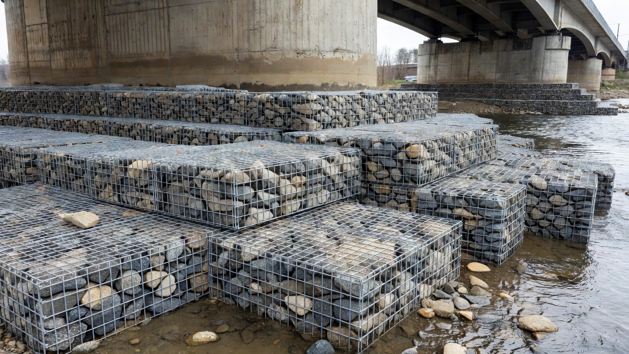
Gabion mattresses are rectangular wire mesh baskets, typically 0.3 m thick, filled with stone and laced together to form a continuous mattress. Gabion mattresses provide a semi-flexible, permeable armor layer. Design follows HEC-23 Design Guideline 15 and NCHRP Report 593 Appendix F.
Gabion mattress limitations include: (1) wire mesh corrosion in aggressive environments — galvanized wire may last 10–15 years; PVC-coated wire extends this to 25–30 years; (2) vulnerability to ice and debris damage that cuts or abrades the mesh; (3) limited flexibility compared to loose riprap; and (4) difficulty of inspection of stone inside the baskets. Gabions are most appropriate for channel bank stabilization rather than pier scour protection.
{{
Partially grouted riprap consists of conventional riprap with voids partially filled with cementitious grout — typically filling 30–40 percent of the void space. The grout binds the stones at their contact points while maintaining flexibility and permeability. This technique originated in Germany (Bundesanstalt für Wasserbau, BAW) and has been adopted in the United States through NCHRP Report 593.
Partially grouted riprap provides: (1) significantly higher resistance to shear failure than loose riprap of the same stone size — up to 2–3 times the critical shear velocity; (2) reduced stone displacement without eliminating permeability; (3) improved hydraulic efficiency (lower Manning’s n); and (4) protection against winnowing. The primary disadvantage is reduced flexibility — once the grout cures, the system cannot self-heal as well as loose riprap. If the grout layer fractures under bed deformation, the fractured sections can detach and fail. Partially grouted riprap is most suitable for critical pier locations where stone displacement is unacceptable and some flexibility is still required.
Grout bags (also called grout-filled fabric mats or grout mattresses) are fabric bags filled with cementitious grout, typically 150–300 mm thick, placed directly on the prepared subgrade. The bags conform to the bed surface and cure to form a continuous, impermeable armor layer. Design follows NCHRP Report 593 Appendix H.
Advantages include: (1) impermeable layer eliminates winnowing entirely; (2) rapid installation — bags can be injected underwater using grout pumps; (3) minimal stone requirement; and (4) smooth surface reduces hydraulic roughness. Disadvantages include: (1) complete rigidity leads to fracture under differential settlement; (2) repair requires removal of large fractured sections; (3) impermeability can cause uplift pressures to build beneath the mattress if not properly vented; and (4) UV degradation of fabric over time.
The GEOMAT grout-filled mattress system uses three layers — woven geotextile bottom, high-strength spacer fabric core, and woven geotextile top — stitched together into mattress panels. When filled with cementitious grout, the system forms a continuous reinforced concrete matrix with controlled thickness (typically 100–200 mm). The system provides high flexural strength, uniform coverage, and rapid installation. Testing in NCHRP Report 593 demonstrated excellent performance at bridge piers for velocities up to 6 m/s.
Riprap maintenance is driven by inspection findings. The following thresholds define action levels:
Routine maintenance — Performed annually or biennially as part of scheduled bridge inspection. Includes removal of woody vegetation (root diameter >25 mm), replacement of individual displaced stones, localized stone addition to restore layer thickness in settled areas, and geotextile repair where fabric is exposed and damaged. Typically triggered by B.C.10 ratings of 6 or 7.
Major maintenance — Performed when riprap displacement exceeds 20 percent of the surface area, layer thickness has reduced below the design minimum in more than 10 percent of the installation, or undermining has progressed more than 0.3 m inward from any edge. Requires mobilization of equipment for stone delivery, placement, and filter repair. Typically triggered by B.C.10 ratings of 4 or 5.
Replacement — Required when riprap is extensively displaced (>50 percent of area), filter layer is compromised across more than 30 percent of the installation, stone quality has deteriorated below specification, or the failure modes have resulted in pier exposure or settlement. Replacement involves removal of existing riprap, subgrade re-preparation, new filter installation, and re-armoring with properly sized stone. Typically triggered by B.C.10 ratings of 0–3.
Post-flood inspection is mandatory after any flood event exceeding the 2-year recurrence interval, per NBIS requirements. Post-flood inspection should compare riprap condition against baseline records and focus specifically on edge displacement, filter exposure, and stone loss on the upstream faces of piers.
While riprap is primarily associated with bridge scour protection, it is also specified for airfield drainage structures under FAA Advisory Circular AC 150/5320-5D, Airport Drainage Design. Riprap is used at culvert outlets, headwalls, energy dissipators, channel transitions, and outfall structures within airport drainage systems.
At airports, riprap must be sized per FAA guidance for the calculated discharge velocity at the drainage structure outlet. The stone must be clean, hard, durable, and resistant to freeze-thaw cycles — typically granite, basalt, or quartzite with specific gravity exceeding 2.60 and absorption less than 2.0 percent. The filter layer (geotextile or granular) is equally critical in airport applications to prevent soil piping from the pavement subgrade layers.
ICAO Annex 14, Volume I (Aerodrome Design and Operations) requires that airport drainage systems be designed to protect pavements and structures from water damage, though it does not prescribe specific riprap design methodology — this is left to national standards (FAA AC 150/5320-5D in the United States). Riprap at airport drainage structures is typically inspected during routine airfield pavement inspections per ICAO Doc 9137, Part 9 (Airport Maintenance Practices), with special attention after heavy rain events that produce high-velocity outflow at culvert outlets.
The same riprap failure modes apply at airport drainage structures as at bridge piers, with the additional risk that failed riprap can become foreign object debris (FOD) on airfield pavements, creating a direct hazard to aircraft operations. Stones displaced from riprap at culvert outlets adjacent to runways or taxiways must be immediately removed and the riprap repaired. This makes regular inspection of airport drainage riprap — particularly after storm events — a safety-critical function for airfield maintenance personnel.
TarmacView provides AI-powered bridge inspection tools to detect riprap displacement, settlement, and scour damage from visual data. Automate your scour countermeasure condition assessments and streamline NBIS reporting.
Scour is the erosion or removal of streambed or bank material around bridge foundations (piers and abutments) due to flowing water, the leading cause of bridge ...
An abutment is the end support structure of a bridge that retains the approach embankment, transfers superstructure loads to the foundation, and accommodates th...
A bridge pier is an intermediate vertical support structure between abutments that transfers superstructure loads to the foundation. Multi-column bents, wall pi...