Dry Pack Mortar
Dry pack mortar is a very stiff, low-water-content cement mortar rammed into confined repair areas (spall pockets, cone bolt holes, narrow slots), achieving hig...
37 min read
Concrete Repair
Airport Pavement Maintenance
+3
Roller-Compacted Concrete (RCC) is a zero-slump concrete placed with asphalt paving equipment and compacted with vibratory rollers, providing a strong, durable pavement at lower cost than conventional PCC. Covers RCC mix design, placement, jointing, surface texture, and inspection for typical RCC distresses.
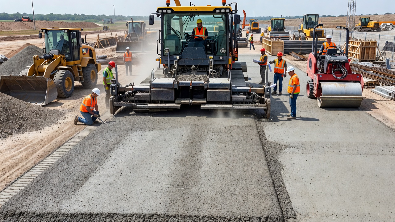
Roller-Compacted Concrete (RCC) pavement is a type of non-reinforced concrete pavement constructed using a zero-slump concrete mix placed with high-density asphalt paving equipment and compacted to final density using vibratory and pneumatic rollers. Unlike conventional portland cement concrete (PCC) pavement, RCC contains no steel reinforcement, no dowel bars, no tie bars, and forms are not required. The material achieves its structural capacity through the physical interlock of densely compacted aggregate particles bound by a hydrated cement paste matrix. The American Concrete Institute (ACI) Committee 327 defines RCC as “concrete compacted by roller compaction — a construction method that uses asphalt-type paving equipment and roller compaction to produce a high-quality, durable concrete pavement.”
The defining characteristic of RCC is its zero-slump consistency — the concrete has a stiff, no-slump appearance similar to damp gravel, with a Vebe consistency typically between 30 and 90 seconds when tested per ASTM C1176. This dry consistency allows the freshly placed concrete to support the weight of compaction rollers immediately after the paver passes, which is essential for the construction process. The RCC mix has a water-to-cementitious materials ratio (w/cm) in the range of 0.30 to 0.45 by mass, significantly lower than the 0.40 to 0.55 range typical of conventional paving concrete. This low w/cm, combined with high compactive effort, produces a dense concrete matrix with very low permeability — typically less than 1,000 coulombs when tested per ASTM C1202 (Rapid Chloride Permeability Test).
Compressive strengths for RCC typically range from 4,000 to 6,000 psi (28 to 42 MPa) at 28 days for standard applications, with strengths up to 10,000 psi (70 MPa) achievable for high-performance mixtures using supplementary cementitious materials. Flexural strengths (modulus of rupture) range from 550 to 800 psi (4 to 6 MPa), which is comparable to or higher than conventional paving concrete for equivalent cementitious content. The elastic modulus of RCC ranges from 4 to 6 million psi (28 to 40 GPa), similar to conventional concrete.
RCC was first developed in the 1970s for the Canadian logging industry, which needed a low-cost, high-strength pavement that could withstand tracked vehicles, massive loads, and hydraulic fluid spills in log-sorting yards. The technology has since expanded worldwide to applications including port and intermodal facilities, military hardstands and tank trails, airport aprons and taxiways, industrial processing yards, highway shoulders and intersections, and municipal streets. The RCC Pavement Council estimates that over 100 million square yards of RCC pavement have been constructed in North America alone since the 1980s.
Key characteristics that distinguish RCC from conventional concrete pavement include:
| Characteristic | RCC Pavement | Conventional PCC Pavement |
|---|---|---|
| Slump | Zero (Vebe 30–90 s) | 1–4 in (25–100 mm) |
| Placement equipment | Asphalt paver (high-density) | Slipform paver or fixed forms |
| Compaction | Vibratory + pneumatic rollers | Internal vibration |
| Steel reinforcement | None | Dowels, tie bars, mesh |
| Joint spacing | 20–40 ft (6–12 m) | 15–20 ft (4.5–6 m) |
| Surface texture | As-rolled or diamond ground | Tined, broom, or grooved |
| Typical cost | 15–30% less than PCC | Baseline |
| Construction speed | 300–500 cy/hr | 100–200 cy/hr |
| Air entrainment | Not effective | Required for freeze-thaw |
The cementitious materials content in RCC is expressed as a percentage of the total dry materials (cement plus aggregates). For wearing course applications, cementitious materials typically constitute 11 to 15 percent of the total dry weight, with 12 to 14 percent being most common. A typical starting point for mix design is 470 to 550 lb of cementitious materials per cubic yard (280 to 330 kg/m³). Type I or Type II portland cement per ASTM C150 is standard. Supplementary cementitious materials (SCMs) including fly ash (Class C or F per ASTM C618) at 15 to 30 percent replacement, ground granulated blast furnace slag per ASTM C989 at 25 to 50 percent replacement, or silica fume per ASTM C1240 at 5 to 10 percent replacement are widely used to improve workability, reduce heat of hydration, lower cost, and enhance long-term strength and durability.
The optimum cementitious content is determined through laboratory testing using the soil compaction method per ACI 327. For a range of cementitious contents (e.g., 11, 13, and 15 percent), moisture-density relationships are established per ASTM D1557 (modified Proctor). At each cementitious content, the optimum moisture content is identified as the water content producing maximum dry density. Cylinders or beams are then compacted at the optimum moisture content for each cementitious level, cured, and tested at the specified age (typically 7, 28, and 90 days) for compressive strength per ASTM C39 or flexural strength per ASTM C78. The required cementitious content is selected from the strength-versus-cementitious-content curve to meet the design flexural or compressive strength plus a margin for variability.
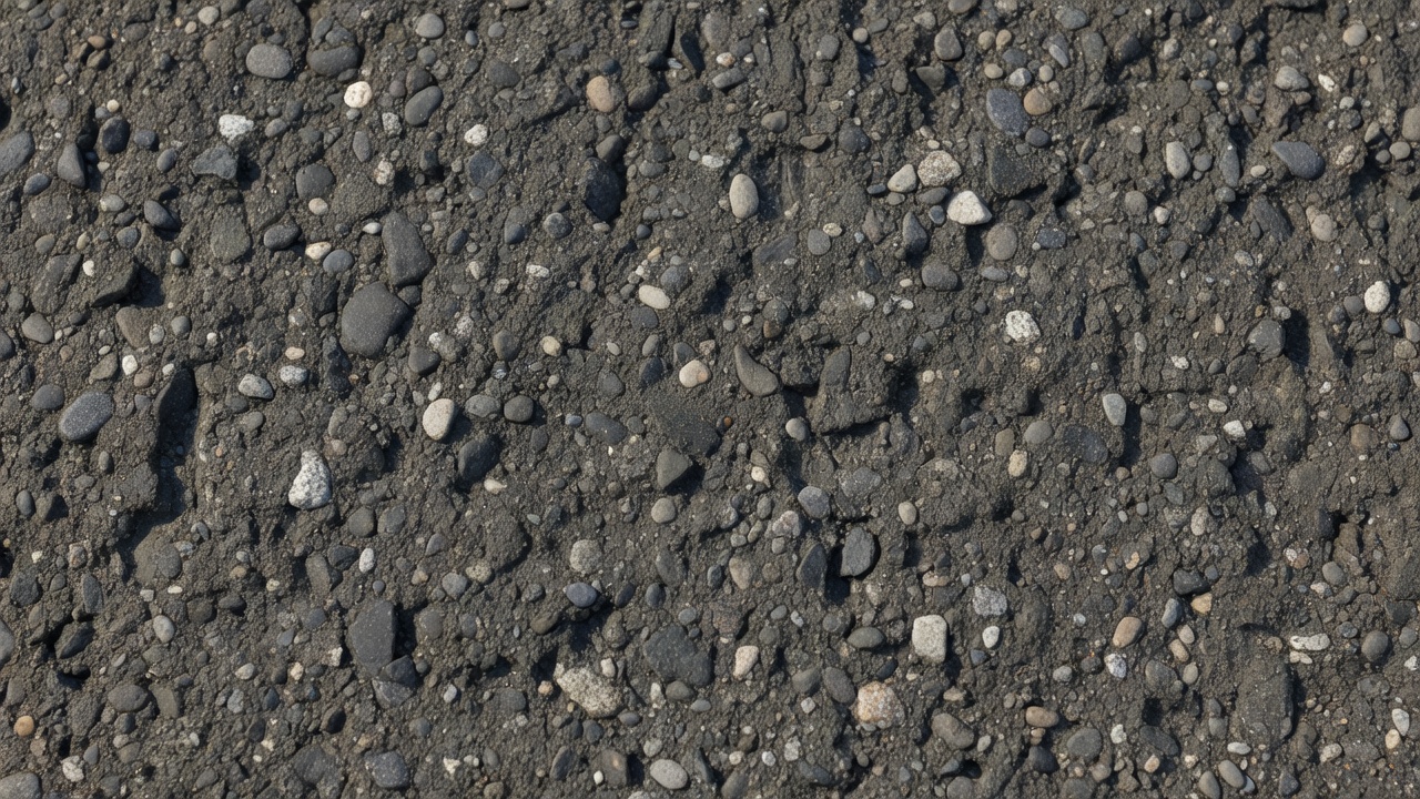
RCC uses dense-graded aggregates that contain a higher percentage of fine aggregate than conventional concrete. The aggregate gradation should approach the 0.45 Power Curve for maximum packing density, which minimizes the void space between particles and reduces the paste volume required. The recommended nominal maximum aggregate size (NMAS) is 3/4 inch (19 mm) for most applications, with 5/8 inch (16 mm) or 1/2 inch (12.5 mm) used where a tighter surface finish is desired. The finer maximum size produces a tighter surface finish that is less prone to wear.
A typical RCC aggregate gradation band per ACI 327 and UFGS 32 13 16.16 follows these limits:
| Sieve Size | Percent Passing (Range) |
|---|---|
| 1 in (25 mm) | 100 |
| 3/4 in (19 mm) | 90–100 |
| 3/8 in (9.5 mm) | 60–85 |
| No. 4 (4.75 mm) | 40–60 |
| No. 16 (1.18 mm) | 20–40 |
| No. 50 (0.30 mm) | 8–22 |
| No. 100 (0.15 mm) | 4–12 |
| No. 200 (0.075 mm) | 2–8 |
The high proportion of particles passing the No. 200 sieve (typically 4 to 8 percent) is essential for producing a workable, compactable mix that achieves a tight surface finish. Crushed aggregate is preferred over rounded gravel because the angular particles provide better aggregate interlock, higher flexural strength, and a more stable surface. For the Portland International Airport RCC project, processed asphalt concrete aggregate (crushed material) was selected specifically because it is less susceptible to segregation during placement and produces higher flexural strengths than rounded gravel.
Water content is the most critical variable in RCC mix design because it determines both the compactability of the fresh concrete and the strength of the hardened concrete. The water content in RCC is expressed as a percentage of the total dry weight (cement plus aggregate), typically ranging from 5 to 8 percent. This corresponds to a water-to-cementitious materials ratio of approximately 0.30 to 0.45 by mass. The exact optimum water content is determined from the moisture-density relationship test (modified Proctor, ASTM D1557), where the water content producing maximum dry density is identified as the optimum moisture content (OMC).
Vebe consistency (ASTM C1176) is the primary measure of RCC workability. The Vebe test uses a cylindrical mold (typically 6-inch diameter for RCC) filled with concrete, mounted on a vibrating table with a transparent plastic disc applying a standard surcharge weight. The Vebe time is the duration in seconds required for the concrete to fully consolidate under combined surcharge and vibration. For RCC pavement mixtures, Vebe times range from 30 to 90 seconds, with the following general guidance:
| Vebe Time | Consistency | Application |
|---|---|---|
| Less than 30 s | Very wet | May not support roller; limited use |
| 30 to 45 s | Plastic | Suitable for thin lifts, moderate compaction |
| 45 to 75 s | Stiff | Optimal for most RCC pavements |
| 75 to 90 s | Very stiff | High compaction effort required; good for thick lifts |
| Greater than 90 s | Extremely stiff | Difficult to compact; not recommended |
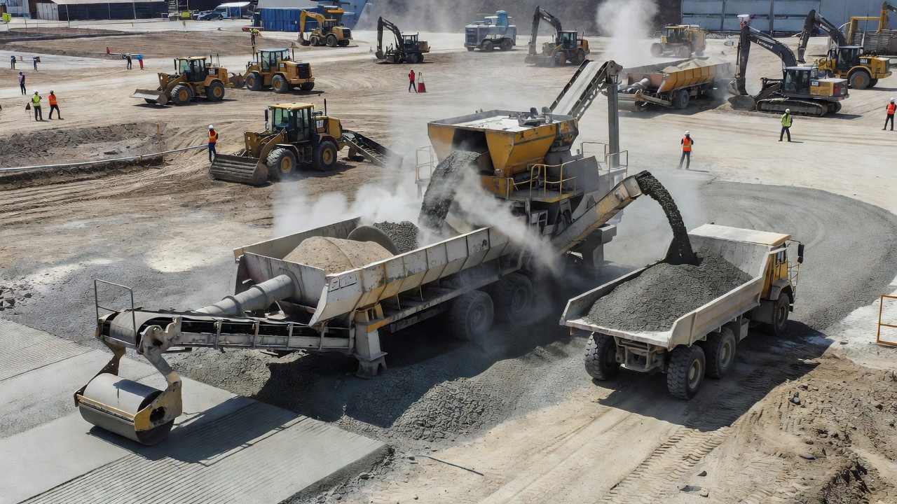
Proper water content at the point of placement is crucial. If the mix is too wet (Vebe under 30 seconds), the roller may sink or cause surface waves. If too dry (Vebe over 90 seconds), the mix cannot be compacted to target density, resulting in high void content, low strength, and poor durability. The target Vebe time must be adjusted for ambient temperature, wind, and evaporation rate, as water loss during transport and placement can increase Vebe time by 10 to 30 seconds. The use of a continuous mixing plant (pugmill) allows precise control of water addition and provides the most consistent RCC production.
The high-density paver is the cornerstone of successful RCC construction. These machines are specifically modified asphalt pavers equipped with tamping bars and vibratory screeds that provide pre-compaction of the RCC before rolling begins. The tamping bars, operating at 800 to 2,000 strokes per minute, impact the concrete and force aggregate particles into a denser arrangement. The vibratory screed operates at 2,000 to 3,500 vpm, further consolidating the material and leveling the surface. Together, these systems achieve a discharge density of 90 to 92 percent of maximum dry density, meaning the paver accomplishes up to 90 percent of the total compaction work.
High-density pavers are typically track-mounted for stability on the RCC surface and for the higher tractive forces required to propel the machine through the stiff concrete. Key features include automatic grade control systems (stringline or laser-based), proportional feed systems to maintain uniform concrete distribution across the full paving width, and screed extensions for variable lane widths. The paver places RCC in lifts of 4 to 10 inches (100 to 250 mm) at widths up to 30 feet (9 m). Production rates of 300 to 500 cubic yards per hour are achievable with a properly sized paver. For lifts exceeding 10 inches, RCC is placed in multiple lifts. A material transfer device (MTD) is recommended between the dump trucks and the paver to provide a continuous, uniform feed and to reduce segregation.
Conventional asphalt pavers (without tamping bars) have been used for RCC placement on smaller projects but are not recommended for lifts over 6 inches (150 mm). They achieve only 85 to 90 percent discharge density, resulting in greater reliance on rolling for compaction. This increases the risk of surface tearing, shoving, and poor ride quality. The U.S. Army Corps of Engineers UFGS 32 13 16.16 specification explicitly requires high-density pavers for military RCC projects.
Aggregate spreaders (modified dozers or graders) have been used for RCC placement on very low-budget projects, but they produce poor surface smoothness, uneven density, and high segregation. Their use is not permitted on military, airport, or highway projects per standard specifications.
Compaction of RCC to achieve 96 to 98 percent of maximum dry density is essential for strength, durability, and surface wear resistance. The compaction process follows a three-stage rolling sequence performed immediately behind the paver.
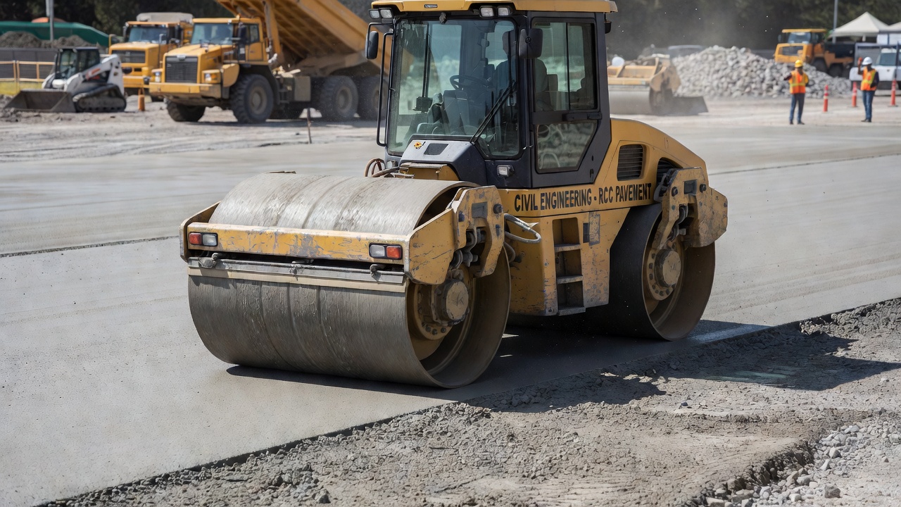
The primary compaction rolling is performed using steel drum vibratory rollers with a minimum static weight of 10 tons (90 kN), with 12 to 15 ton rollers being preferred. These rollers operate in vibratory mode at frequencies of 2,500 to 3,500 vibrations per minute (vpm) with an amplitude setting appropriate for the lift thickness — low amplitude (0.015 to 0.025 inches) for lifts under 6 inches, and higher amplitude (0.030 to 0.050 inches) for lifts of 6 to 10 inches. The rolling pattern typically consists of two to four vibratory passes followed by two to three static passes (vibration off). Each pass overlaps the previous one by 6 to 12 inches. The rolling speed is maintained at 2 to 3 mph (3 to 5 km/h) to ensure adequate compactive effort per pass.
The time window between concrete discharge and final rolling is critical — it should not exceed 60 minutes under normal ambient conditions (70°F, 21°C). In hot, dry, or windy conditions, the allowable window may decrease to 30 to 45 minutes. The end of the allowable time window is defined as the moment when the concrete can no longer be compacted to target density without surface tearing. If the concrete stiffens beyond this point, it must be removed and replaced.
The final rolling stage uses a pneumatic-tired roller (rubber-tired roller) weighing 15 to 30 tons to seal the surface, close any remaining surface voids, and produce a smooth, tight finish. The pneumatic roller operates in static mode, typically making two to four passes at a speed of 3 to 5 mph (5 to 8 km/h). The kneading action of the rubber tires closes surface porosity and embeds any exposed aggregate particles, producing the characteristic dense, tight surface of well-constructed RCC. Tire pressure of 90 to 110 psi is typical.
During construction, field density is monitored continuously using nuclear density gauges in direct transmission mode per ASTM D6938. Testing is performed immediately after each rolling pass to track density gain and determine the required number of passes. The optimum rolling pattern is established during the test section constructed at the start of the project, where the contractor demonstrates the combination of paver speed, roller type, roller passes, and vibration settings that consistently achieves target density.
Transverse contraction joints are the most important joint type in RCC pavement. They are sawed or formed to control the location of cracking as the concrete shrinks during curing and thermal contraction. Joint spacing for RCC is typically 20 to 40 ft (6 to 12 m) for slab thicknesses up to 10 inches. For thicker slabs (10 to 14 inches), joint spacing may be extended to 40 to 60 ft (12 to 18 m), as thicker slabs develop lower tensile stresses from temperature and moisture gradients. The ratio of joint spacing to slab thickness (L/T) typically ranges from 24 to 48 for RCC, compared to approximately 20 for conventional pavement.
Saw cut timing is critical — cuts must be made after the concrete has gained sufficient strength to prevent raveling during sawing but before uncontrolled cracking develops. This timing is typically 4 to 24 hours after placement, depending on ambient temperature, concrete strength development, and lift thickness. In hot weather, sawing may begin as early as 4 hours; in cool weather, it may be delayed to 18 to 24 hours. Early-entry dry-cut saws with diamond blades are preferred for RCC, as they minimize water introduction that could cause surface deterioration. The saw cut depth should be a minimum of T/4 to T/3 of the slab thickness, with T/4 (25 percent) being the minimum recommended by the RCC Pavement Council to provide a controlled crack plane through the full slab depth.
Load transfer at transverse joints in RCC is achieved through aggregate interlock rather than dowel bars. The dense-graded angular aggregate in RCC provides excellent interlock, with load transfer efficiencies typically exceeding 70 percent for tight joints (crack widths less than 0.02 inches). As the joint opens with thermal contraction and drying shrinkage, load transfer efficiency decreases but remains adequate for most heavy-duty applications. No dowel bars are used in RCC pavement, which is a fundamental difference from conventional jointed concrete pavement.
Longitudinal joints in RCC are the construction joints between adjacent paving lanes. Two types exist:
Fresh longitudinal joints occur when the adjacent lane is placed within 60 minutes of the previous lane. In this case, the fresh joint can be rolled in tandem — the roller operates with one drum on the fresh concrete and the other on the adjacent lane — creating a monolithic bond between the two lanes. No joint preparation is required. Cold longitudinal joints occur when more than 60 minutes elapse between lanes. For cold joints, the edge of the first lane is trimmed back 6 to 12 inches to create a clean, vertical face. The trimmed face is cleaned and lightly moistened before the second lane is placed. Cold joints have very limited load transfer (less than 20 percent) and act as a weakened plane where longitudinal cracking can occur if the joint is not properly bonded.
UFGS 32 13 16.16 specifies that RCC pavement lane width should not exceed 20 ft (6 m). If the paving width is greater than 20 ft, intermediate longitudinal contraction joints should be provided at spacing not less than 10 ft.
Joint sealing in RCC is optional and depends on the application. For most industrial and heavy-duty applications, joints are left unsealed. For airport pavements, parking structures, and facilities where water infiltration must be minimized, joints may be sealed with a hot-poured or cold-applied sealant per ASTM D6690 or ASTM D5893. The sealant reservoir is formed by widening the saw cut to the specified dimensions, typically 0.5 inches wide by 1.0 inches deep for the sealant, with the lower portion of the cut serving as the crack inducer.
The surface texture of RCC pavement is fundamentally different from conventional concrete pavement because RCC cannot be tined, broom-finished, or textured in the plastic state. The dry, stiff consistency prevents these operations. Surface texture options for RCC are limited to post-hardened treatments.
The as-rolled surface is the natural finish produced by the paver and roller compaction sequence. It is dense, tight, and smooth but has a mottled appearance with exposed fine aggregate particles. The surface exhibits a slight texture from the roller drums and tires. While adequate for low-speed industrial applications (20 to 30 mph), the as-rolled surface typically does not provide sufficient macrotexture for high-speed traffic or aircraft operations. The mean texture depth (MTD) of as-rolled RCC, measured by the sand patch test per ASTM E965, is typically 0.01 to 0.03 inches (0.2 to 0.8 mm), below the FAA minimum of 0.03 inches for runways and high-speed taxiways.
Diamond grinding is the most reliable method for achieving a high-quality surface texture on RCC. Diamond-tipped grinding heads mounted on a self-propelled grinding machine cut longitudinal grooves 0.06 to 0.10 inches wide at a spacing of 0.20 to 0.25 inches, producing a corduroy-like texture with macrotexture depths of 0.03 to 0.06 inches (0.8 to 1.5 mm). Diamond grinding also improves ride quality by removing surface irregularities, typically reducing the International Roughness Index (IRI) from 100 to 150 inches/mile to 50 to 80 inches/mile. Diamond grinding is standard for RCC airport pavements and highway applications where surface friction and smoothness requirements are most demanding.
Diamond grooving uses narrower, deeper cuts (0.10 to 0.20 inches wide by 0.25 to 0.50 inches deep) at closer spacing (0.50 to 0.75 inches) than diamond grinding. Grooving provides drainage channels that reduce hydroplaning risk and improve wet weather friction. For airport pavements, transverse grooving is common per FAA AC 150/5320-6C. For highways, longitudinal grooving improves directional stability and reduces noise.
Burlap drag is possible on RCC only when surface-active admixtures or retarding sprays are applied to the surface immediately after rolling. These admixtures delay the surface set, allowing a burlap drag to be performed 2 to 4 hours after placement. The resulting texture is similar to conventional concrete’s burlap finish but is shallower and less uniform. This technology is relatively recent (developed in the 2010s) and the long-term durability of the surface texture is still being evaluated.
A thin asphalt concrete overlay (HMA cap) of 1.5 to 3 inches (38 to 75 mm) can be placed over RCC to provide a smooth, friction-textured riding surface. This approach combines the structural strength of RCC with the surface characteristics of asphalt. It is used on some highway projects where the RCC provides the structural pavement and the asphalt provides the wearing course.
Transverse cracking is the most common distress in RCC pavement, particularly when contraction joints are not provided. The cracking results from restrained shrinkage — as the concrete cools and dries after hydration, tensile stresses develop due to subgrade friction and the pavement’s own weight. Natural crack spacing in unjointed RCC ranges from 20 to 40 ft (6 to 12 m) for typical slab thicknesses of 8 to 12 inches. The cracks are generally tight (less than 1/16 inch or 1.5 mm wide) with good aggregate interlock providing load transfer efficiencies of 50 to 80 percent. Wider cracks (greater than 1/8 inch) can develop under severe thermal conditions or on subgrades with high friction, and these wider cracks may experience spalling, water infiltration, and pumping of subgrade fines.
Crack activity is highest during the first 90 days after construction, during which the concrete undergoes the majority of drying shrinkage and initial thermal contraction. After the first year, crack movement stabilizes at approximately ±0.01 to 0.03 inches per 10°F temperature change. For jointed RCC pavements, some intermediate cracking between sawed joints is not uncommon, particularly if the saw cut timing is delayed or the joint spacing is excessive.
Surface wear (abrasion) occurs in RCC pavements exposed to tracked vehicles, steel-wheeled traffic, or snowplows. The surface paste (the thin layer of cement mortar at the surface) can erode, exposing fine aggregate particles that may become dislodged. Severe wear can lead to raveling, where the surface becomes rough and aggregate particles are lost. Surface wear is most pronounced when:
Surface wear is measured in terms of depth of surface loss (typically 0.02 to 0.10 inches per year of heavy traffic) or by visual classification. Diamond grinding the surface removes the weak surface paste and exposes the dense internal matrix, significantly improving wear resistance.
Spalling at joints and cracks is the chipping or breaking of concrete at the edges of the saw cut. Causes include:
Spall severity is classified as low (loss of concrete within 2 inches of the joint, less than 1 inch deep), moderate (2 to 6 inches from the joint, 1 to 2 inches deep), or high (more than 6 inches from the joint, more than 2 inches deep). High-severity spalling at joints may require full-depth repair.
Longitudinal cracking along construction joints indicates poor bond between adjacent paving lanes. It occurs when the time between adjacent lane placements exceeds 60 minutes and the cold joint preparation is inadequate, or when the transverse joint saw cuts do not align at the longitudinal joint. Longitudinal cracks are typically tight but can develop into wider cracks over time, particularly under traffic loading that causes differential deflection across the crack.
Pumping is the ejection of water and fine-grained soil material from beneath the pavement through joints, cracks, or the pavement edge under the action of traffic loading. It occurs when:
Pumping leads to void formation beneath the pavement (loss of support), which increases deflections and accelerates pavement deterioration. It is most common in RCC pavements on fine-grained subgrades without a stabilized base layer.
In-place density testing is the primary acceptance test for RCC pavement. Nuclear density gauges(NDG) calibrated for RCC are used in direct transmission mode per ASTM D6938. The gauge measures wet density, dry density, and moisture content simultaneously through a probe inserted into a predrilled hole in the fresh concrete. Test frequency is typically one test per 500 square yards (420 m²) per lift, with a minimum of four tests per day’s production. Test locations should be randomly selected but distributed across the day’s placement.
The acceptance criterion is percent compaction relative to the maximum dry density (MDD) determined from the modified Proctor test (ASTM D1557). For most specifications:
Core density testing (ASTM C642) on extracted cores provides a secondary check on field density values. Cores are taken at a frequency of approximately one per 1,000 square yards, typically at 7 to 14 days after placement. The core density provides a direct measurement of the hardened concrete density, which should be 95 to 98 percent of MDD.
Pavement thickness is verified by core measurement and by taking depth measurements during construction. The specification tolerance is typically ±0.5 inches (12 mm) from the design thickness. Payment adjustment may apply for deficiencies. Areas where the measured thickness is less than 90 percent of the design thickness require corrective action, which may include removal and replacement or an overlay.
Surface smoothness is evaluated using a 10-ft (3-m) straightedge placed parallel to the pavement centerline. The acceptable deviation is typically ±1/4 inch (6 mm) under the straightedge, with the deviation measured at the deepest point of the gap. For airport pavements, the tolerance may be tightened to ±1/8 inch (3 mm) per FAA standards. Areas exceeding the tolerance require diamond grinding or corrective action. For large projects, an inertial profiler may be used to measure the International Roughness Index (IRI), with target IRI values of 80 to 120 inches/mile (1.3 to 1.9 m/km) for industrial pavements and 40 to 70 inches/mile (0.6 to 1.1 m/km) for highways.
Joint inspection includes verification of:
Visual inspection of the RCC surface documents:
A complete distress survey is performed at 28 days and again at 1 year after construction to establish the baseline condition and monitor crack development.
RCC pavement design for heavy-duty applications follows the same principles as conventional rigid pavement design, modified for the specific material properties of RCC. The primary design inputs are:
For airport pavements, the FAA Advisory Circular 150/5320-6C methodology is used. The pavement is designed as a rigid pavement using the Westergaard edge-loading condition, with the flexural strength of the concrete and the k-value of the subgrade/subbase as inputs. The design procedure yields the required slab thickness for each aircraft type, and the critical aircraft (the one requiring the greatest thickness) governs the design. For the PDX airport project, the design aircraft was the Boeing 727 (gross weight 154,500 lb), yielding a 14-inch RCC section over 4 inches of aggregate base.
For military applications, design follows UFC 3-250-01FA. When transverse joints are provided, a 10 percent thickness reduction is allowed to account for estimated 25 percent load transfer at the joints. Without joints, a free-edge condition is assumed (0 percent load transfer), resulting in thicker sections.
Load transfer in RCC pavements is provided entirely by aggregate interlock at joints and cracks. The dense-graded, angular aggregates used in RCC interlock mechanically when the joint or crack faces are in compression. Load transfer efficiency (LTE) is measured as the ratio of deflection on the unloaded side to deflection on the loaded side of the joint. For tight joints (less than 0.02 inches wide), LTE of 70 to 90 percent is typical. As the joint opens with temperature and moisture changes, LTE decreases to 50 to 70 percent. The FAA requirement for new rigid pavement joints is a minimum LTE of 75 percent. RCC does not use dowel bars, so LTE depends entirely on aggregate interlock.
The first major airport RCC application — Portland International Airport (PDX), constructed in 1985 — has performed well over its service life. The 14-inch RCC parking apron was designed for 700 psi flexural strength and has supported B747, DC-10, B767, and B727 aircraft without structural failure. Surface wear was noted in areas of heavy turning traffic, which was addressed through diamond grinding. The PDX project demonstrated that RCC can meet airport surface tolerance requirements (±0.03 ft elevation, ±1/4 inch per 10 ft straightedge) and provide the durability required for commercial aircraft loading.
Military applications include over 400,000 square yards at Fort Drum (1988), tank hardstands at Fort Hood, equipment shop facilities, and tank trails. The early military RCC pavements showed variable performance, with some projects experiencing surface wear and cracking. Improved construction technology, including high-density pavers, better quality control, and proper jointing, has significantly improved performance for projects constructed since 2000.
RCC and conventional PCC pavement differ in material properties, construction methods, performance characteristics, and cost. The table below provides a comprehensive comparison:
| Property | RCC Pavement | Conventional PCC Pavement |
|---|---|---|
| Mix consistency | Zero-slump (Vebe 30-90 s) | Slump 1-4 in (25-100 mm) |
| Water-cement ratio | 0.30-0.45 | 0.40-0.55 |
| Cementitious content | 11-15% of dry weight (470-550 lb/cy) | 12-16% (470-600 lb/cy) |
| Aggregate gradation | Dense-graded, high fines | Gap-graded or dense-graded |
| Maximum aggregate size | 3/4 in (19 mm) typical | 1.5-2 in (38-50 mm) |
| Compaction method | Vibratory + pneumatic rollers | Internal vibration |
| Placement equipment | Asphalt paver (high-density) | Slipform paver |
| Steel reinforcement | None | Dowels, tie bars, mesh |
| Joint spacing | 20-40 ft | 15-20 ft |
| Load transfer | Aggregate interlock only | Dowel bars + aggregate interlock |
| Surface texture | As-rolled or diamond ground | Tined, broom, or grooved in plastic state |
| Air entrainment | Not effective | Required for freeze-thaw |
| Compressive strength (28d) | 4,000-8,000 psi | 3,500-6,000 psi |
| Flexural strength (28d) | 550-800 psi | 500-700 psi |
| Time to open to traffic | 24-48 hours | 7-14 days |
| Construction speed | 300-500 cy/hr | 100-200 cy/hr |
| Relative cost | 70-85% of PCC cost | Baseline |
| Smoothness (IRI) | 80-150 in/mi (as-rolled); 40-80 in/mi (ground) | 50-80 in/mi |
| Friction (BPN) | 50-60 (as-rolled); 60-75 (ground) | 55-75 |
| Field density acceptance | 96-98% of MDD | Does not apply |
| Core density acceptance | 95-98% of MDD | Does not apply |
RCC is preferred over conventional PCC when:
Conventional PCC is preferred when:
The following standards and guidance documents govern the design, construction, and evaluation of RCC pavements:
| Standard | Title | Applicability |
|---|---|---|
| ACI PRC-327-24 | Roller-Compacted Concrete Pavements — Guide | Comprehensive design and construction guidance |
| UFGS 32 13 16.16 | Roller Compacted Concrete (RCC) Pavement | U.S. military specifications |
| ASTM D1557 | Modified Proctor Compaction | Maximum dry density determination |
| ASTM C1176 | Making and Curing Test Specimens for RCC | Specimen fabrication for lab testing |
| ASTM C1435 | Molding RCC Cylinder Specimens Using Vibrating Hammer | Alternative specimen fabrication |
| ASTM D6938 | In-Place Density by Nuclear Gauge | Field density acceptance |
| ASTM C642 | Density, Absorption, and Voids in Hardened Concrete | Core density testing |
| ASTM C78 | Flexural Strength of Concrete (Third-Point Loading) | Design strength verification |
| FAA AC 150/5320-6C | Airport Pavement Design and Evaluation | Airport pavement design |
| UFC 3-250-01FA | Pavement Design for Roads, Streets, Walks, and Open Storage Areas | Military pavement design |
| ICAO Doc 9157 | Aerodrome Design Manual Part 3 — Pavements | International airport pavement guidance |
The following table summarizes the key quality control parameters for RCC pavement construction per UFGS 32 13 16.16 and ACI PRC-327-24:
| Parameter | Specification | Test Method | Frequency |
|---|---|---|---|
| Maximum dry density (MDD) | Establish per mix | ASTM D1557 | Per mix design |
| Optimum moisture content (OMC) | Establish per mix | ASTM D1557 | Per mix design |
| Field density | 96% minimum of MDD | ASTM D6938 (nuclear) | 1 per 500 sq yd |
| Core density | 95% minimum of MDD | ASTM C642 | 1 per 1,000 sq yd |
| Compressive strength (28d) | 4,000 psi minimum | ASTM C39 (from cores or cylinders) | 3 per 5,000 sq yd |
| Flexural strength (28d) | As designed (typically 550-800 psi) | ASTM C78 | Per project spec |
| Vebe consistency | 30-90 seconds | ASTM C1176 | 1 per 50 cy |
| Slab thickness | ±0.5 in of design | Core measurement | At each core location |
| Surface smoothness | ±1/4 in per 10 ft straightedge | Straightedge | 1 per 500 ft lane |
| Joint depth | T/4 minimum | Depth gauge | 1 per 10 joints |
| Joint spacing | Per design | Tape measure | Every joint |
| Curing compound coverage | Per manufacturer spec | Wet film gauge | Per batch |
Roller-Compacted Concrete pavement is a mature, cost-effective pavement technology that combines the structural performance of concrete with the construction speed of asphalt. Its zero-slump mix, placed with high-density asphalt pavers and compacted with vibratory rollers, produces a dense, high-strength pavement at 15 to 30 percent lower cost than conventional concrete. RCC has been successfully used for airports, military facilities, ports, industrial yards, and highways for over 40 years. The key to successful RCC construction is achieving target density (96 to 98 percent of maximum dry density) through proper mix design, equipment selection, and rolling procedures. While RCC has limitations — primarily in surface texture, jointing control, and the inability to incorporate steel reinforcement — it remains the pavement of choice for large-area, heavy-duty applications where economy and speed of construction are paramount.
Our team provides comprehensive pavement evaluation services including RCC condition surveys, distress identification, density testing, and forensic investigation for airfield and industrial pavements.
Dry pack mortar is a very stiff, low-water-content cement mortar rammed into confined repair areas (spall pockets, cone bolt holes, narrow slots), achieving hig...
Pervious concrete (also called permeable or porous concrete) is a concrete with high interconnected void content (15-35%) allowing water to pass through, reduci...
Fiber-Reinforced Concrete (FRC) contains distributed short fibers (steel, synthetic macro, glass, carbon, natural) to control cracking, improve toughness, and r...