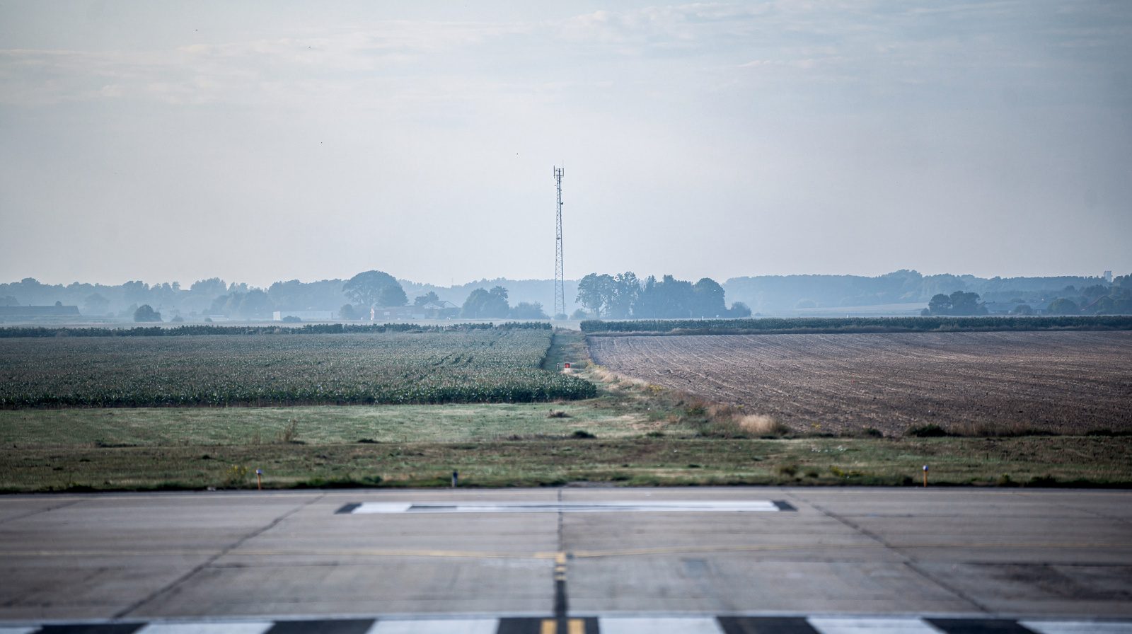
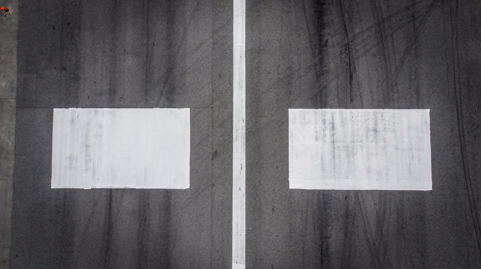
What is a Runway End Safety Area (RESA)?
A Runway End Safety Area (RESA) is a defined, graded, and cleared area located beyond the end of a runway strip, symmetrical about the extended runway centerline. It serves as the last line of physical defence for an aircraft that overruns (exits the far end of the runway during landing or a rejected takeoff) or undershoots (touches down short of the runway threshold). Per the ICAO definition in Annex 14 Volume I, Chapter 1, Aerodromes, the RESA is “an area symmetrical about the extended runway centre line and adjacent to the end of the strip primarily intended to reduce the risk of damage to an aeroplane undershooting or overrunning the runway.”
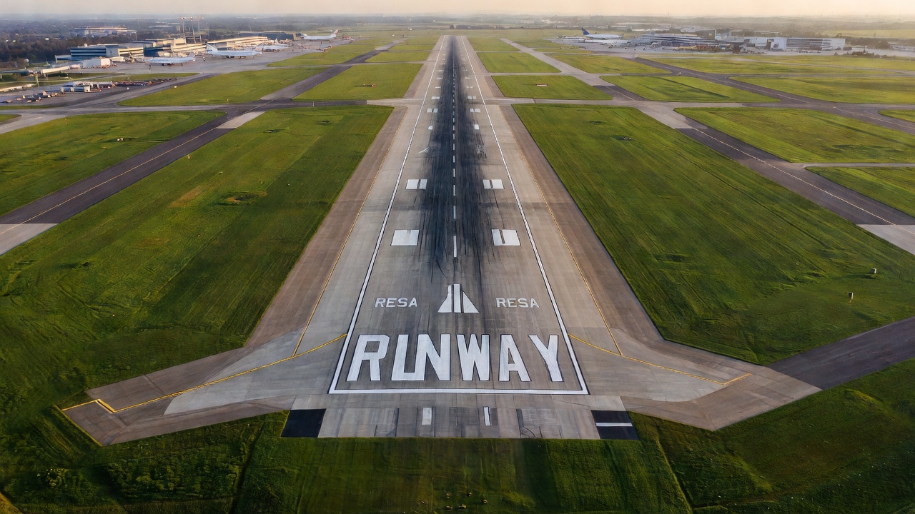
Where used: RESA is a standard element of every runway at civil aerodromes that serve international air traffic. It is referenced in ICAO Annex 14, ICAO Aerodrome Design Manual (Doc 9157, Part 1), national civil aviation regulations, and airport inspection checklists worldwide. RESA condition is specifically inspected during aerodrome certification audits, safety oversight inspections, and runway safety assessments conducted by civil aviation authorities.
Definition and Purpose
The fundamental purpose of a RESA is energy management. When an aircraft overruns the runway pavement, it carries significant kinetic energy. A properly designed and maintained RESA provides a surface that allows the aircraft to decelerate safely by rolling resistance, controlled soil/grass friction, and momentum dissipation without striking hard obstacles, dropping into drainage ditches, or encountering abrupt terrain changes that could cause structural collapse, fuel spill ignition, or occupant injury.
RESA fulfills multiple safety functions simultaneously. It reduces the severity of runway excursions by providing a predictable, load-bearing surface that supports the weight of an aircraft without causing it to sink, tip, or break apart. It supports the movement of rescue and fire fighting (RFF) vehicles, ARFF apparatus must be able to access any part of the runway via the RESA within the required response time of 3 minutes to the midpoint of the furthest runway per ICAO Annex 14 Chapter 9. It also supports snow removal equipment (SRE) during winter operations, allowing snowploughs to turn around and stage at runway ends without encroaching on obstacle limitation surfaces.
RESA also prevents the creation of a step change or vertical drop-off between the runway pavement end and the adjacent terrain. Without a graded RESA, the runway pavement edge could present a vertical face of up to 40-50 cm (the depth of the pavement structure including base and subbase layers) relative to the natural ground level. An aircraft leaving the pavement at speed and encountering such a drop-off would likely suffer landing gear collapse, wing structural failure, or fuel tank rupture. The graded RESA eliminates this hazard by providing a smooth, continuous transition from the paved runway surface to the natural or engineered ground beyond.
RESA Dimensions (ICAO Annex 14, FAA)
RESA dimensional requirements are specified in ICAO Annex 14 Volume I, Chapter 3 (Physical Characteristics), Section 3.4, Runway End Safety Areas. The requirements are classified as Standards (mandatory, using “shall”) and Recommended Practices (advisory, using “should”) and vary according to the Aerodrome Reference Code of the runway.
ICAO Annex 14 RESA Dimensional Requirements
The Aerodrome Reference Code consists of two elements: Code Number (1-4) based on aeroplane reference field length, and Code Letter (A-F) based on wingspan and outer main gear wheel span. RESA length requirements are tied to the Code Number.
| Runway Code Number | RESA Length (Standard, minimum) | RESA Length (Recommended) | RESA Width |
|---|---|---|---|
| Code 1 (Non-Instrument) | 30 m | 80 m | At least twice runway width |
| Code 1 (Instrument) | 60 m | 120 m | At least twice runway width |
| Code 2 | 60 m | 120 m | At least twice runway width |
| Code 3 | 90 m | 240 m | At least twice runway width |
| Code 4 | 90 m | 240 m | At least twice runway width |
The RESA width must extend symmetrically on each side of the extended runway centerline to at least twice the width of the associated runway. For a Code 4E runway of 45 m width, the RESA must be at least 90 m wide (45 m each side of centerline). Where a runway has a stopway or clearway, the RESA requirements still apply beyond those features.
The 90 m / 240 m distinction is critical. To understand the operational logic behind ICAO’s recommended 240 m: this length was derived from statistical analysis of historical overrun events. Data from the Flight Safety Foundation and ICAO’s Runway Excursion Risk Analysis showed that a RESA of 240 m would contain approximately 95% of overrun events for Code 3 and 4 aeroplanes operating in normal conditions. The 90 m minimum, by contrast, covers approximately 60-70% of events. Airports that can only provide a 90 m RESA due to existing infrastructure constraints are expected to justify this through a safety risk assessment and implement mitigating measures, most commonly the installation of an Engineered Materials Arresting System (EMAS).
FAA Runway Safety Area (RSA) Dimensions
The FAA equivalent of RESA is called the Runway Safety Area (RSA), defined in FAA Advisory Circular 150/5300-13B (Airport Design) and FAA Order 5200.8 (Runway Safety Area Program). Unlike ICAO’s code-based system, FAA RSA dimensions are based on the Airplane Design Group (ADG) and Approach Visibility Minimums of the runway’s critical aircraft.
| Aircraft Approach Category | Approach Speed (Vref) | Standard RSA Length Beyond Runway End | Standard RSA Width |
|---|---|---|---|
| Category A & B | Less than 121 knots | 240 m (800 ft) | 120 m (400 ft) |
| Category C & D | 121 knots or greater | 305 m (1,000 ft) | 152 m (500 ft) |
| Category E | Helicopters / special | 305 m (1,000 ft) | 152 m (500 ft) |
FAA Order 5200.8 requires all Part 139 certificated airports to perform an RSA determination for each runway end, documenting the area available and any incompatible land (terrain, drainage structures, roadways, etc.). Where the determined RSA dimensions do not match the standard dimensions, the RSA is classified as nonstandard, and the airport operator must implement the Runway Safety Area Program, which includes identifying mitigation measures, scheduling improvements, and filing progress reports.
RESA at Displaced Thresholds
When a runway threshold is displaced, the area between the displaced threshold and the start of the runway is not available for landing, but may be used for takeoff. ICAO Annex 14 requires that a cleared and graded area of at least 60 m in length be available between the unserviceable area and the displaced threshold. This area effectively functions as a RESA for aircraft that undershoot the displaced threshold during landing.
RESA Grading and Surface Requirements
The physical surface of a RESA must meet strict grading and preparation standards specified in ICAO Annex 14 Section 3.4 and detailed in ICAO Aerodrome Design Manual (Doc 9157, Part 1) Chapter 7. The governing principle is that the RESA surface must be capable of supporting an aeroplane in the event of an overrun or undershoot without causing structural damage to the aircraft and must also support the passage of rescue and fire fighting vehicles.
Longitudinal and Transverse Slopes
| Slope Type | Code 3 and 4 Runways | Code 1 and 2 Runways |
|---|---|---|
| Longitudinal slope (upward, from runway end outward) | Not to exceed 2.5% | Not to exceed 3% |
| Longitudinal slope (downward, from runway end outward) | Not to exceed 5% | Not to exceed 5% |
| Transverse slope (perpendicular to centerline) | Not to exceed 3% | Not to exceed 3% |
These slope limitations are designed so that an aircraft leaving the runway pavement at speed will not encounter a slope change sufficient to cause the nose gear to dig in (causing a pitch-over event) or the main gear to experience asymmetric loading. The 5% downward slope limit addresses the case where the RESA terrain drops away from the runway, if the downward slope is too steep, an aircraft may become airborne briefly after leaving the pavement, then impact the ground with greater force.
Surface Preparation
The RESA surface must be graded and cleared of all material that could present a hazard to an overrunning aircraft or to ARFF vehicles. Specific requirements include:
- Removal of large rocks and debris: The RESA surface must be free of stones, rocks, or loose objects larger than approximately 7-10 cm in diameter, as these could be ingested by aircraft engines, strike the fuselage, or cause tyre failure.
- Turf/vegetation cover: The area must be planted with a stable, erosion-resistant grass cover or equivalent surface treatment. Turf provides rolling resistance that helps decelerate a departing aircraft while preventing soil erosion from jet blast and rainfall.
- Load-bearing capacity: ICAO recommends a California Bearing Ratio (CBR) of 15-20 for the RESA surface, matching the design requirement for the graded portion of the runway strip. This ensures that the surface can support occasional aircraft loading without rutting or failure. The CBR requirement is confirmed in ICAO working papers on Annex 14 compliance (ICAO AP-ADO-TF-5).
- Drainage: The RESA must be graded to prevent water ponding. Standing water in a RESA creates hidden depth hazards (an aircraft may sink into soft saturated soil), wildlife attractant, and frost heave potential in cold climates. A properly graded RESA drains laterally to collector ditches or subsurface drainage systems.
- Frost protection: In cold climate aerodromes, the RESA subgrade must be protected against frost heave that could create uneven surfaces. This may require granular subbase layers or insulation boards similar to those used under the runway pavement structure.
Obstacle Clearance within RESA
Annex 14 Section 3.4.7 states that “the runway end safety area shall, as far as practicable, be clear of all objects except frangible objects that are required to be situated in the area for air navigation purposes.” This is one of the most commonly cited findings during aerodrome safety inspections.
What is permitted in a RESA:
- Frangible visual aids: Approach lighting structures, precision approach path indicator (PAPI) units, and runway end identification lights (REILs) may be located in the RESA provided they are mounted on frangible couplings that will break away on impact with minimal resistance.
- Instrument landing system (ILS) antenna arrays: The localizer antenna is typically located beyond the far end of the RESA, but in constrained situations the glide path antenna or localizer may penetrate the RESA volume. Where permitted, these must be mounted on frangible supports per FAA AC 150/5220-23.
- Perimeter roads and fences: These must be located outside the RESA or, where they unavoidably cross it, designed with frangible gates, breakaway posts, and no raised curbs.
What is prohibited in a RESA:
- Non-frangible structures (buildings, equipment shelters, permanent signs)
- Drainage channels with vertical walls or drop inlets without grated covers
- Roadways with raised curbs or guardrails
- Parking areas, vehicle storage, fuel storage facilities
- Navigation aids with non-frangible supports
- Trees, poles, or utility structures
- Storage of materials or equipment (even temporary)
The ICAO definition of frangible is specified in Annex 14 as “an object of low mass designed to break, distort, or yield on impact so as to present the minimum hazard to an aircraft.” The frangible connection must fail at a load significantly below the structural load that would cause damage to an aircraft striking it.
RESA vs Stopway vs Clearway
These three terms describe distinct areas beyond the runway end, each with a different function in aerodrome design and declared distance calculations.
| Feature | RESA | Stopway | Clearway |
|---|---|---|---|
| Primary function | Safety area for overrunning/undershooting aircraft | Area for aborted takeoff stopping | Area for initial climb after takeoff |
| Load-bearing capacity | Must support aircraft (CBR 15-20) | Must support aircraft (same as runway) | No load-bearing requirement |
| Width | At least 2× runway width | Same width as runway | At least 150 m (narrow at origin, expands) |
| Length counted in declared distances? | No | Yes (in ASDA) | Yes (in TODA) |
| Surface preparation | Graded, cleared, turfed | Paved or prepared surface | Unobstructed airspace, no surface requirement |
| ICAO reference | Annex 14, 3.4 | Annex 14, 3.5 | Annex 14, 3.6 |
Practical distinction: A stopway is a load-bearing area that can be used in the calculation of Accelerate-Stop Distance Available (ASDA), the distance required for an aircraft to accelerate to V1 then stop after an engine failure. A clearway is an airspace area used in the calculation of Take-off Distance Available (TODA), the distance available for the aircraft to climb to 35 ft after takeoff. A RESA is not counted in any declared distance, its sole purpose is safety in the event of a runway excursion.
Obstacle Clearance within RESA
The obstacle environment within and adjacent to the RESA is governed by ICAO Annex 14 Chapter 4 (Obstacle Restriction and Removal) and Chapter 6 (Visual Aids for Navigation). The RESA itself forms part of the approach and take-off obstacle limitation surfaces, and any object that penetrates these surfaces requires specific approval.
Frangible Object Requirements
All objects permitted in the RESA must be frangible. FAA Advisory Circular 150/5220-23 defines frangible connections as structural joints that fail at a load not exceeding 28 kN (6,300 lbf) for approach lighting structures and proportionally lower loads for smaller fittings. The frangible connection must separate cleanly with no protruding sharp edges after failure.
Examples of typical RESA-located frangible installations:
- Approach lighting system (ALS) towers: These are typically lattice structures with frangible base connections spaced at 30 m intervals for 900 m (CAT I) or 300 m (CAT II/III) approach lighting patterns. Each tower must break away when struck by an aircraft without causing structural damage to the wing or fuselage.
- PAPI (Precision Approach Path Indicator) units: The four PAPI light boxes for each runway end are usually located within or adjacent to the RESA. They are mounted on frangible bases that shear off at ground level on impact.
- Runway End Identification Lights (REILs): These synchronized flashing lights are installed at the runway threshold to help pilots identify the runway end. Their frangible mount is typically a low-profile fitting less than 30 cm above ground.
Prohibited Objects and Common Inspection Findings
During aerodrome inspections, the following are frequently cited as non-compliances:
- Construction equipment or materials stored temporarily in the RESA during maintenance works (even overnight storage is prohibited)
- Soil erosion control materials (silt fences, straw bales) left in place after construction work is complete
- Temporary signage or barricades that are not frangible
- Vegetative growth exceeding the allowable height (trees, shrubs, tall grass)
- Drainage structures with exposed vertical walls, open channels, or ungrouted riprap
- Wildlife habitats such as ponds or wetlands that develop naturally within the RESA
- Road signs, light poles, or utility structures on perimeter roads that lean into the RESA volume
The height restriction for objects in a RESA is effectively zero, no object that is not frangible and required for air navigation is permitted above grade level.
RESA Inspection (Grading, Erosion, Foreign Objects, Pavement Condition)
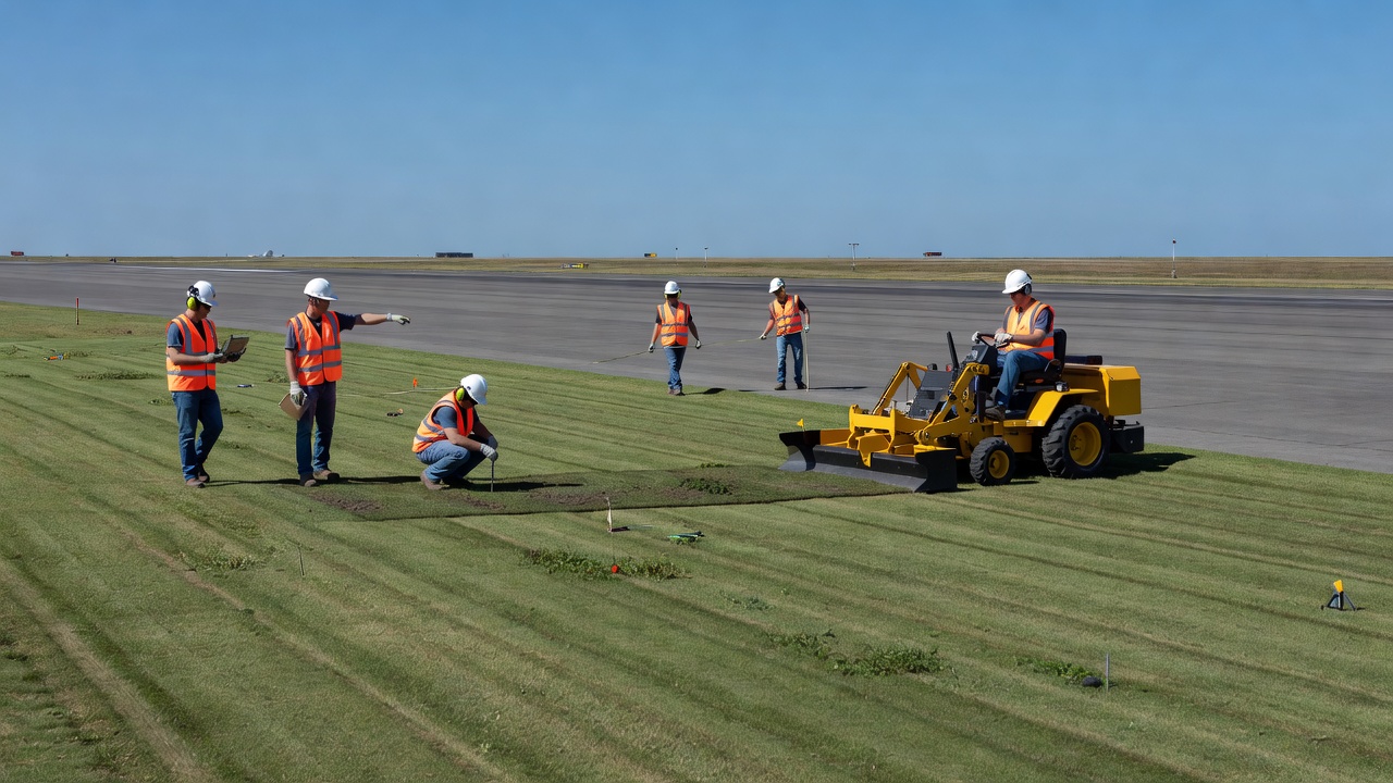
RESA condition inspection is a mandatory component of daily, weekly, and periodic aerodrome inspection programmes as required by ICAO Annex 14 Section 9.2 and national regulations such as FAA Part 139 (Airport Certification). The inspection scope covers four main areas:
Grading Inspection
Inspectors must verify that the RESA surface maintains the required longitudinal and transverse slopes. Over time, erosion, settlement, or construction activity can alter the graded profile. Key checks include:
- Surface uniformity: Visual inspection for depressions, hummocks, ridges, or washboarding that could cause an aircraft to bounce or lose directional control
- Transverse slope verification: Using surveying instruments or laser levels to confirm transverse slopes do not exceed 3% (especially after heavy rainfall or frost thaw)
- Longitudinal slope verification: Checking the upward/downward gradient from the runway end outward against the 2.5% / 5% limits
- Edge transitions: Checking where the RESA meets surrounding terrain, there must be no vertical drop-offs, exposed pipes, or erosion gullies at the perimeter
Erosion Control Inspection
Erosion within the RESA is a common finding at airports in regions with high rainfall, steep adjacent terrain, or poor turf establishment. Erosion gullies, if left unaddressed, can deepen to 30-60 cm within a single wet season, creating a serious hazard for overrunning aircraft.
- Rill and gully formation: Small channels (rills) that concentrate water flow can become deep gullies that would trap an aircraft’s landing gear
- Jet blast erosion: Areas directly behind the runway end often suffer from turf loss due to jet exhaust. Annex 14 recommends that erosion protection measures (turf reinforcement mats, geotextiles, sodding) extend at least 60 m from the runway end and preferably 90 m for Code 4 runways
- Bare soil patches: Any area where vegetation cover is lost must be reseeded or resodded promptly to prevent erosion progression
- Slope instability: Checking for signs of slumping or mass movement on RESA side slopes
Foreign Object Debris (FOD) Inspection
The RESA must be maintained free of FOD. Common FOD sources in the RESA include:
- Debris blown by jet blast from surrounding areas
- Construction debris from nearby works
- Stones and gravel displaced from unpaved access roads
- Vegetative debris (branches, dead grass clumps)
- Wildlife carcasses or nest materials
FAA Advisory Circular 150/5210-24A (Airport Foreign Object Debris Management) requires a daily daylight inspection of all aircraft operating areas including RESAs. FOD found during inspection must be documented by location, type, and quantity, and trend analysis performed to identify recurring sources.
Pavement Condition at Runway-RESA Interface
The transition from rigid/asphalt runway pavement to the graded RESA surface is a critical inspection point. Common issues include:
- Pavement edge spalling or cracking: The exposed edge of the runway pavement at the RESA boundary is vulnerable to freeze-thaw damage, vegetation intrusion, and mechanical damage from snow ploughs
- Pavement overhang: If the RESA surface erodes below the pavement base level, the pavement edge may be left unsupported (overhanging), leading to structural failure under aircraft load
- Seal failure: The joint between the pavement end and the RESA base course must be sealed to prevent water ingress that causes subgrade softening and frost heave
| Inspection Item | Frequency | Method | Common Deficiencies |
|---|---|---|---|
| Grading (slopes) | Annually + after major earthworks | Survey/laser level | Erosion altering transverse slopes |
| Turf/vegetation cover | Monthly (growing season) | Visual inspection | Bare patches, weed infestation |
| Erosion gullies | Weekly (wet season) | Visual inspection | Rill/gully formation depth >10 cm |
| FOD | Daily (daylight) | Walking/driving inspection | Stones, debris, construction waste |
| Frangible objects | Annually | Physical inspection | Corroded frangible couplings |
| Pavement edge | Monthly | Visual + sounding | Spalling, cracking, overhang |
| Drainage | After heavy rain | Visual + flow check | Blocked outlets, ponding |
Engineered Materials Arresting System (EMAS) in RESA
An Engineered Materials Arresting System (EMAS) is a passive aircraft arresting system that can be installed in a RESA when the available distance does not meet the standard requirement. EMAS consists of a bed of lightweight, crushable cellular concrete material that absorbs the kinetic energy of an overrunning aircraft by controlled deformation as the aircraft’s landing gear rolls through the material.
How EMAS Works
The EMAS bed is constructed from blocks of cellular cementitious material with a controlled compressive strength (typically 0.3-0.6 MPa). When an aircraft rolls into the EMAS bed, the landing gear tires crush the cellular concrete, generating a predictable deceleration force that brings the aircraft to a stop. The material is designed so that:
- The deceleration forces do not exceed the structural limits of the aircraft (typically limited to 1.5 g longitudinal deceleration)
- The aircraft remains in the normal (wheels-down) attitude throughout the stop
- The fuselage and wings are not contacted by the arresting material
- The system functions in all weather conditions, rain, snow, ice, standing water
- The system can be restored after a single arrest by replacing the crushed material
EMAS Standards
| Parameter | FAA Specification | ICAO Guidance |
|---|---|---|
| Effective stopping speed | 70 knots for critical aircraft | 70 knots recommended |
| Bed length | Varies by aircraft type (typically 90-180 m) | Equivalent to missing RESA length |
| Bed width | Full RESA width | Full RESA width |
| Bed depth | 0.3-0.6 m (typical) | Per manufacturer design |
| Material | Cellular concrete (crushable) | Cellular concrete or equivalent |
| Load rating | Must stop design aircraft | Must stop critical aircraft |
FAA and ICAO Equivalency
The FAA considers an EMAS installed in accordance with AC 150/5220-22 (Engineered Materials Arresting Systems for Aircraft Overruns) to provide a level of safety equivalent to a standard 305 m (1,000 ft) RSA. This equivalency is critical for airports constrained by terrain, roads, railways, waterways, or existing development that prevents achieving the standard RSA dimensions.
ICAO Annex 14 Section 3.4.17 states that “where a runway end safety area of 240 m cannot be provided, the length recommended in 3.4.15, an arresting system may be installed to compensate for the shorter length.” The arresting system must be designed, tested, and maintained per the specifications in ICAO Aerodrome Design Manual Part 1, Chapter 7.
As of 2025, there are over 130 EMAS installations at airports worldwide, with the majority in the United States (FAA approval) and growing adoption in Europe, Asia, and the Middle East. Major installations include John F. Kennedy International Airport (JFK), Chicago O’Hare (ORD), London City Airport (LCY), and Singapore Changi (SIN).
RESA at Existing Airports (Shortfall Management)
Many existing airports were built before modern RESA standards were adopted (ICAO introduced the 90 m minimum in 1999 and the 240 m recommendation in later amendments). Retrofitting a full-standard RESA at an existing airport often encounters physical constraints:
Common Constraints
- Public roads or highways located near the runway end
- Railway lines running parallel to or crossing near the runway axis
- Water bodies (rivers, lakes, coastal waters) immediately beyond the runway
- Built-up areas (residential, commercial, industrial) that cannot be acquired
- Topography (steep slopes, cliffs, valleys) that prevents economic grading
- Environmental constraints (wetlands, protected habitats, archaeological sites)
Mitigation Measures for RESA Shortfall
Where the full standard RESA cannot be achieved, ICAO Annex 14 requires the airport operator to conduct a safety risk assessment and implement appropriate mitigation measures. The hierarchy of mitigation includes:
- EMAS Installation: The preferred mitigation, provides equivalent safety to a full-length RESA and is recognised by both ICAO and FAA
- Runway end redesign: Shortening the runway pavement to allow more space for RESA (reduces operational capacity but may be the only option for severe constraints)
- Displaced threshold: Moving the landing threshold inward to increase the overrun area available (reduces LDA but not TORA)
- Operational restrictions: Limiting the runway to smaller aircraft, reduced takeoff weights, or specific weather conditions
- Enhanced safety procedures: Implementing runway excursion risk mitigation (ERRM) programmes, additional approach lighting, and crew training
ICAO’s Aerodrome Design Manual Part 1 provides a decision matrix for evaluating RESA shortfall scenarios. The key principle is that a 90 m minimum is the absolute floor for Code 3 and 4 runways, and any RESA shorter than 90 m requires regulatory approval with non-standard conditions.
RESA and Runway Safety
RESA is one component of the broader runway safety ecosystem that includes runway strips, declared distances, obstacle limitation surfaces, and operational procedures. Runway excursions, both overruns and veer-offs, remain the most common type of aviation accident worldwide, accounting for approximately 30% of all commercial aviation accidents annually according to IATA and ICAO data.
Statistical Context
- IATA’s Annual Safety Report indicates that runway excursions constituted 24% of all global aviation accidents in 2023
- Of those, approximately 55% were overruns and 45% were veer-offs
- A properly designed and maintained RESA could potentially mitigate or eliminate casualties in >80% of overrun events according to EASA safety studies
- The presence of an adequate RESA was identified as a contributing factor in the survivability of several high-profile overrun events, including the 2016 Emirates Boeing 777 overrun at Dubai International Airport (DXB)
RESA in Runway Safety Programmes
Airport operators run various runway safety programmes that directly involve RESA management:
- Runway Safety Teams (RST): Multi-stakeholder groups that review excursion risks and RESA condition as part of continuous improvement cycles
- Runway Excursion Risk Reduction (RERR): ICAO’s framework for identifying and mitigating excursion risks, with RESA adequacy as a key performance indicator
- Aerodrome Certification Audits: National aviation authorities review RESA compliance as part of certification renewal, typically every 1-3 years depending on jurisdiction
| Safety Measure | RESA Contribution |
|---|---|
| Overrun prevention | N/A (operational measure, not physical) |
| Overrun consequence mitigation | Primary physical barrier, provides stopping distance |
| Veer-off prevention | RESA side grading minimises roll-over risk |
| Undershoot mitigation | RESA at approach end reduces landing short impact |
| ARFF access | RESA provides vehicle access to all runway parts |
| Snow removal staging | RESA allows equipment turn-around at runway ends |
RESA Maintenance
Maintaining a RESA to its design standard requires an ongoing maintenance programme covering turf, grading, drainage, objects, and surface integrity.
Turf Maintenance
The grass surface of a RESA must be maintained to specific standards:
- Mowing height: Typically maintained at 10-20 cm (4-8 inches). Grass that is too short may not provide adequate erosion protection, grass that is too tall may conceal FOD, drainage defects, or wildlife
- Fertilisation and irrigation: Required in arid climates to maintain vegetative cover. The grass species should be selected for deep root systems, drought tolerance, and compatibility with the local soil and climate
- Re-sodding: Bare patches larger than 1 m² must be re-sodded or hydroseeded within 30 days (per FAA guidance for Part 139 airports)
- Weed control: Invasive species with deep taproots (thistles, dandelions, woody weeds) must be controlled as they create surface irregularities and attract wildlife
Drainage Maintenance
The RESA drainage system (surface grading, swales, subsurface drains) must be kept functional:
- Culvert and outlet clearing: Performed quarterly and after heavy rainfall events
- Swale grading: Checking that surface drainage channels maintain their design cross-section and gradient
- Subsurface drain flushing: Required annually to remove sediment and root intrusion
- Ponding areas: Any area where water stands for more than 24 hours must be investigated and corrected
Grading Restoration
Over time, the RESA profile degrades due to:
- Settlement: Fine-grained soils compact and settle, altering slopes
- Erosion: Surface runoff removes soil from the graded surface
- Cracking in arid soils: Desiccation cracks in clay soils create irregular surfaces
- Vehicle traffic: Maintenance vehicle tracks create ruts that become preferential flow paths for erosion
Periodic re-grading (typically every 3-5 years for turfed RESAs, more frequently in high-erosion environments) is required to restore the design slopes. This involves:
- Topsoil stripping and stockpiling
- Cut and fill to restore longitudinal and transverse grades
- Subgrade compaction to achieve required CBR (15-20)
- Topsoil replacement (minimum 15 cm depth)
- Sodding or hydroseeding
- Fertilisation and watering for establishment
Seasonal Considerations
| Season | Maintenance Focus |
|---|---|
| Spring | Drainage inspection after snowmelt, turf re-establishment, frost heave assessment |
| Summer | Mowing programme, irrigation, erosion control after thunderstorms |
| Autumn | Leaf and debris removal, drainage preparation for winter, final grading |
| Winter | Snow removal staging, frost protection, checking for ice damage to turf |
Record Keeping and Documentation
Maintenance records for RESA must be retained and available for inspection by civil aviation authorities. The following documentation is typically required:
- Daily inspection logs with RESA condition checklists
- Grading survey data (annually or after re-grading)
- Turf establishment records (reseeding dates, species, fertilisation schedule)
- Drainage inspection and maintenance records
- FOD collection logs with trend analysis
- Erosion repair records (date, location, extent, method)
- Frangible object inspection records (condition of frangible couplings, base plates)
These records form part of the aerodrome’s Safety Management System (SMS) documentation and are reviewed during certification audits and safety oversight inspections by the national civil aviation authority.
Frequently Asked Questions
- What is the minimum RESA length required by ICAO?
- For Code 3 and 4 runways (instrument), the minimum RESA length is 90 meters beyond the runway strip end. The recommended length is 240 meters where practicable. For Code 1 and 2 runways, the minimum is 30 meters for non-instrument Code 1 and 120 meters recommended for Code 2. The RESA width must be at least twice the runway width.
- What is the difference between RESA and Runway Safety Area (RSA)?
- RESA is the ICAO term defined in Annex 14, while RSA is the FAA term used in the United States. The FAA RSA extends 1,000 feet (305 m) beyond the runway end and 500 feet (152 m) wide for runways serving Approach Categories C and D aircraft. ICAO's RESA is typically 90 m minimum (up to 240 m recommended) with width of twice the runway width. Functionally both serve the same purpose, providing a cleared, graded area for aircraft that overrun or undershoot.
- Can RESA length be reduced if EMAS is installed?
- Yes. ICAO Annex 14 states that where a RESA of the recommended length (240 m) cannot be provided, an Engineered Materials Arresting System (EMAS) may be installed to compensate for a shorter RESA. The FAA considers an EMAS installed per its specification as equivalent to a standard 305 m (1,000 ft) RSA. The EMAS bed must be designed to stop the critical aircraft entering at 70 knots without causing structural damage.
- What objects are allowed in a RESA?
- Per ICAO Annex 14, the RESA must be cleared and graded and, as far as practicable, clear of all objects except frangible objects that are required to be located in the area for air navigation purposes. No fixed objects other than frangible visual aids (e.g., approach lighting structures) are permitted. Equipment such as ILS localizer antenna arrays must be mounted on frangible couplings per FAA AC 150/5220-23.
- What are the grading requirements for a RESA?
- ICAO Annex 14 specifies that the RESA must have a longitudinal slope not exceeding 2.5% (upward) and 5% (downward), and transverse slopes not exceeding 3%. The surface must be graded to prevent water ponding and to support aircraft and rescue vehicles without causing damage. For Code 3 and 4 runways, the graded portion of the strip extends 75 m each side of the centerline.
This is a reference entry. TarmacView provides drone inspection services and doesn't sell the equipment or materials described in this glossary.