Dynamic Cone Penetrometer (DCP)
The Dynamic Cone Penetrometer (DCP) is a portable field device that measures soil and aggregate strength by recording the penetration rate (mm/blow) of a cone d...
34 min read
geotechnical
pavement
+4
The sand cone test is a volumetric method for determining in-place density of compacted soil by excavating a small hole, weighing the removed soil, and measuring the hole volume with calibrated sand. It is the reference field density method for compaction quality control.
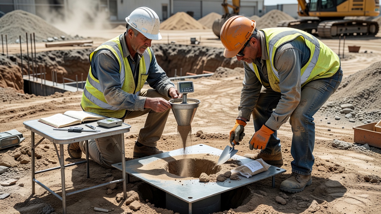
The sand cone test is an in-situ volumetric method for determining the field density and unit weight of compacted soils and soil-aggregate mixtures. The test operates on the principle of sand replacement: a small test hole is excavated in the compacted soil layer, the excavated material is collected and weighed, and the volume of the hole is measured by filling it with calibrated free-flowing sand of known bulk density. From these two measurements — mass of soil removed and volume of the hole — the wet density of the soil is calculated, and after moisture content determination, the dry density and percent compaction are derived.
The sand cone test is standardized under ASTM D1556 — Standard Test Method for Density and Unit Weight of Soil in Place by Sand-Cone Method — and AASHTO T191 — Density of Soil In-Place by the Sand-Cone Method. These standards are technically equivalent and are referenced by construction specifications worldwide. The AASHTO version includes additional guidance specific to transportation agency field operations, including data recording forms and quality control procedures.
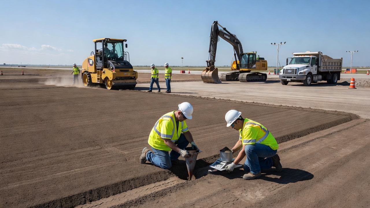
The fundamental purpose of the sand cone test is compaction quality control. Soil compaction specifications are established during the design phase and depend on the anticipated loading conditions. Projects are designed using Proctor compaction tests — standard Proctor (ASTM D698 / AASHTO T99) for general earthworks and embankments, or modified Proctor (ASTM D1557 / AASHTO T180) for pavements and airfields where heavy wheel loads create dynamic forces. These laboratory tests establish the maximum dry density (MDD) and optimum moisture content (OMC) for each soil type. The sand cone test then verifies that the contractor has achieved the specified percentage of MDD in the field — typically 90% to 95% for non-structural areas, 95% to 100% for embankments, and 98% to 100% of modified Proctor for heavily loaded pavement layers.
Beyond compaction acceptance, the sand cone test is used for several other critical purposes. In pavement forensic investigation, the test provides direct measurements of in-place density and moisture content of existing pavement layers, enabling engineers to diagnose performance problems, evaluate whether inadequate compaction contributed to premature failure, and design appropriate rehabilitation strategies. In research applications, the sand cone serves as the reference method for calibrating and validating nuclear density gauges, non-nuclear electromagnetic density gauges, and other rapid field density measurement devices. The sand cone test is also employed in compaction method specification projects where the contractor is required to demonstrate that the achieved density meets or exceeds the specification target.
The sand cone test is suitable for soils and soil-aggregate mixtures that contain particles not exceeding approximately 50 mm (2 inches) in diameter. For soils containing larger particles, the test method requires correction procedures (AASHTO T224) to account for the coarse fraction. The test is not recommended for saturated, highly plastic soils, or for materials where the test hole cannot maintain its shape due to caving or sloughing.
The sand cone apparatus assembly consists of three main components: a container (typically a one-gallon plastic or glass jar), a detachable metal cone with a valve mechanism, and a base plate with a circular opening. The metal cone attaches to the jar and channels sand flow through the valve. The base plate provides a stable template for excavation — it is a flat metal plate, typically 300 mm x 300 mm (12 inches x 12 inches), with a centered circular opening of 165 mm (6.5 inches) diameter. The base plate serves three functions: it defines the excavation boundary, provides a seating surface for the sand cone, and distributes the apparatus weight to prevent disturbance of the test site. Four corner holes accommodate stakes that secure the plate during excavation.
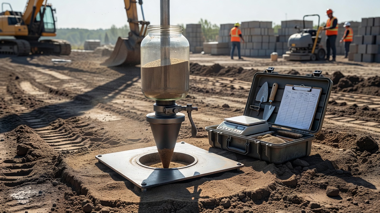
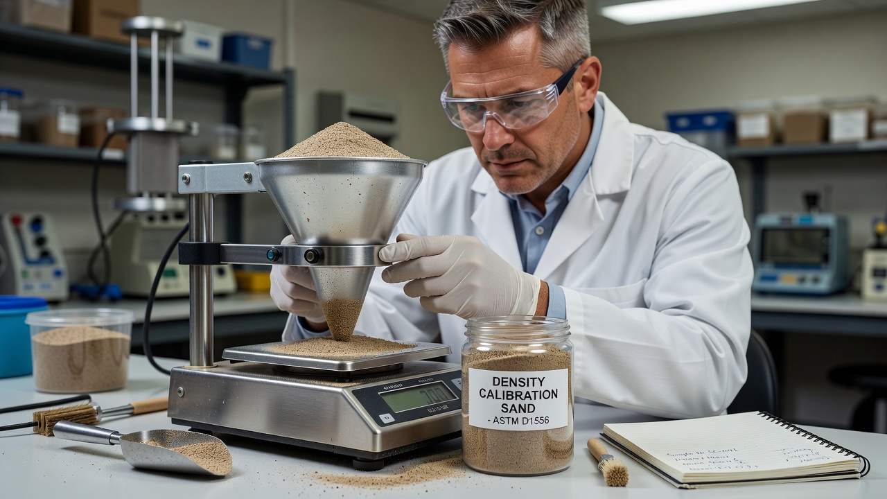
The calibration sand is a critical component. ASTM D1556 specifies that the sand must be clean, dry, free-flowing, and uniform — typically a silica sand passing the No. 10 sieve (2.0 mm) and retained on the No. 40 sieve (0.425 mm). This gradation ensures consistent flow characteristics and a stable bulk density. The sand must be stored in sealed containers to prevent moisture absorption, because even small changes in moisture content alter the sand’s bulk density and introduce systematic error. The bulk density of the sand typically ranges between 1,400 and 1,700 kg/m³ (87 to 106 lb/ft³), depending on the specific gradation and particle shape.
Calibration is performed in two steps. Step One — Cone Correction: The technician fills the apparatus with calibration sand and records the initial weight. The apparatus is inverted onto the base plate, which is placed on a clean, level laboratory surface. The valve is opened, and sand flows into the cone cavity and the gap between the cone rim and the base plate surface. When sand flow stops, the valve is closed, and the apparatus is weighed again. The difference between the initial and final weights is the cone correction — the weight of sand required to fill the cone cavity and base plate gap. This value is unique to each apparatus-base plate pair and must be recalculated if components are interchanged.
Step Two — Bulk Density Determination: A calibration container of known volume (typically 0.028 to 0.057 m³ or 1 to 2 ft³, determined annually per AASHTO T19) is placed on a level surface. The base plate is positioned on top of the calibration container, and the filled apparatus is inverted onto the base plate. The valve is opened, allowing sand to fill both the cone cavity and the calibration container. After flow stops, the valve is closed, and the apparatus is weighed. The net weight of sand that entered the calibration container is calculated by subtracting the cone correction weight from the total weight loss. Dividing this net weight by the container volume yields the bulk density of the sand. The bulk density must be determined to the nearest 0.1 lb/ft³ (1.6 kg/m³) and is recalculated daily or whenever a new bag of sand is opened.
| Calibration Parameter | Description | Reporting Precision |
|---|---|---|
| Cone Correction | Weight of sand to fill cone and base plate gap | Nearest 0.01 lb (5 g) |
| Sand Bulk Density | Weight per unit volume of calibration sand | Nearest 0.1 lb/ft³ (1.6 kg/m³) |
| Calibration Container Volume | Pre-measured volume per AASHTO T19 | Nearest 0.0001 ft³ (2.8 cm³) |
| Calibration Frequency | Daily or with new sand bag | — |
| Sand Gradation | Passing No. 10, retained No. 40 sieve | Per ASTM D1556 |
The sand cone test procedure is divided into five phases: site preparation, excavation, sand filling, weighing, and moisture determination. Each phase requires meticulous attention to detail because errors propagate through the density calculation.
Site Preparation: The technician selects a test location representative of the compacted layer. Loose, uncompacted material is removed from the surface, and the area is leveled. The base plate is positioned, and four metal stakes are driven through the corner holes to secure the plate against movement during excavation. The apparatus is filled with calibration sand, weighed, and the weight is recorded on the test form.
Excavation: Through the circular opening in the base plate, the technician excavates a test hole using a hammer, chisel, and scoop. The hole should be approximately cylindrical, extending through the full depth of the compacted layer being tested. The shape requirements are critical — the hole walls must be relatively smooth and vertical, without overhangs or crevices that would prevent the sand from completely filling the void. ASTM D1556 Section 7.1.5 specifies the minimum hole volume based on maximum particle size. For soils with maximum particle sizes up to 12.5 mm (0.5 in), the minimum hole volume is 0.028 m³ (1 ft³). For soils with particles up to 50 mm (2 in), the minimum volume increases to 0.057 m³ (2 ft³).
All excavated soil material is carefully collected and placed in a pre-weighed, airtight container. Loss of even a small amount of soil during excavation will result in an underestimate of density. The container is sealed immediately to prevent moisture loss.
Sand Filling: After excavation, the base plate is re-positioned over the hole (if it was dislodged), ensuring it sits firmly and level on the undisturbed soil surface. The sand cone apparatus is inverted and seated onto the base plate, with the cone positioned over the hole opening. The valve is opened fully, allowing sand to flow freely into the hole. The sand must be allowed to flow under its own weight — the apparatus must not be tapped, vibrated, or shaken, as this would increase the sand density and cause overfilling of the hole. When sand flow stops completely, indicating the hole and cone cavity are full, the valve is closed. The apparatus is removed and weighed.
Weighing: The final weight of the apparatus is recorded. The difference between the initial apparatus weight and the final apparatus weight represents the total sand that flowed out. From this, the cone correction is subtracted to obtain the net weight of sand that filled only the test hole.
Moisture Determination: The moisture content of the excavated soil is determined using one of several methods. For cohesive soils, the gas-pressure moisture tester (AASHTO T217) or field drying methods (ITM 506) may be used. For granular soils, AASHTO T255 (total evaporable moisture content by drying) is required. The entire soil sample — not just a portion — is dried to accurately determine the moisture content. After drying, the sample is sieved over the No. 4 sieve (4.75 mm), and the weight of material retained on the No. 4 sieve is recorded for coarse particle correction if needed.
The density calculations from sand cone test data follow a logical step-by-step progression, each building on the previous result. The calculations are standardized in ASTM D1556 Section 8 and AASHTO T191, and are typically recorded on standardized forms such as IT-625 (for soils) or TD-320 (for granular materials containing particles larger than 3/4 inch).
Step 1 — Volume of Test Hole: The volume of the excavated hole is calculated using the sand replacement data. The formula is:
V_hole = (W_apparatus_initial - W_apparatus_final - W_cone_correction) / ρ_sand
where:
Step 2 — Wet Density (or Total Unit Weight): The wet density is the total weight of the excavated soil divided by the hole volume:
ρ_wet = W_wet_soil / V_hole
where W_wet_soil is the weight of the moist soil removed from the hole. This value represents the in-place density including both soil solids and pore water.
Step 3 — Moisture Content: The moisture content (w) is the ratio of the weight of water to the weight of dry solids, expressed as a percentage:
w (%) = [(W_wet_soil - W_dry_soil) / W_dry_soil] × 100
The dry weight of the soil is determined after oven-drying at 110°C ± 5°C to constant weight, typically requiring 12 to 24 hours.
Step 4 — Dry Density: The dry density is the wet density adjusted for the moisture content:
ρ_dry = ρ_wet / (1 + w/100)
where w is the moisture content expressed as a percentage. This value represents the density of the soil solids alone and is the value compared to the Proctor maximum dry density.
Reporting Precision: ASTM D1556 Section 9.4 specifies that values should be reported to the following precision: density and unit weight to the nearest 0.1 lb/ft³ (1.6 kg/m³), moisture content to the nearest 0.1%, and volume to the nearest 0.001 ft³ (28 cm³).
Coarse Particle Correction (AASHTO T224): When the soil contains particles retained on the No. 4 sieve (4.75 mm), the field density must be corrected using AASHTO T224. The coarse fraction correction accounts for the fact that the Proctor maximum dry density was determined on the minus No. 4 fraction only. The correction adjusts the field in-place density so it represents only the minus No. 4 material, enabling a valid comparison with the laboratory Proctor value. For materials with particles larger than 3/4 inch (19 mm), the correction procedure specified in AASHTO T224 uses an assumed specific gravity of 2.60 for the coarse material and an assumed moisture content of 2% for the coarse fraction.
Percent compaction is the ratio of the field dry density to the laboratory maximum dry density (MDD), expressed as a percentage:
C (%) = (ρ_dry_field / ρ_dry_max_lab) × 100
This single number is the basis for compaction acceptance on virtually all earthwork and pavement construction projects. The target percent compaction is specified in the contract documents and depends on the material type, the structural layer, and the loading conditions.
For earth embankments and general fill, typical requirements range from 90% to 95% of standard Proctor maximum dry density. For pavement subgrade and base courses, requirements are more stringent — typically 95% to 100% of modified Proctor MDD. For airport pavement subgrade receiving heavy aircraft loads, the FAA requires compaction to at least 95% of modified Proctor, with 98% to 100% required for base courses. These values reflect the critical importance of subgrade and base support in preventing pavement deformation under the high contact pressures of aircraft tires — which can exceed 1,500 kPa (220 psi) for large commercial aircraft.
The project specification also establishes the acceptable moisture content range at the time of compaction. The field moisture content must typically be within -2% to +1% of the laboratory OMC for cohesive soils, or within -3% to +0% for granular materials. Soil compacted too dry will not achieve target density regardless of compactive effort. Soil compacted too wet may achieve target density immediately but will lose strength when pore pressures dissipate and may exhibit excessive post-construction settlement or rutting.
The one-point Proctor test (AASHTO T272) is a rapid field method used to verify that the on-site soil matches the laboratory sample used for the Proctor test. The one-point test compacted a sample of the field soil at its in-place moisture content using the same compactive effort as the original Proctor. The results are plotted against the original moisture-density curve or compared to a family of curves from local soil data to confirm the target MDD and OMC are valid for the material being tested on that day. This is particularly important when soil types vary across a project site.
The sand cone test holds the status of the reference method or referee method for field density determination in geotechnical engineering. This means that when there is a dispute between different density testing methods — for example, between a nuclear gauge result and a contractor’s own testing — the sand cone test is the accepted standard for resolving the discrepancy. The Indiana Department of Transportation, like many state highway agencies, specifies that “field density determination of soil compaction is done in accordance with AASHTO T191 (Sand Cone) or AASHTO T310 (Nuclear Gauge),” with the sand cone being the primary method and the nuclear gauge being an alternative when properly correlated.
The sand cone test earns its reference status through several inherent advantages. First, it is a direct physical measurement — it literally measures the volume of the excavated hole and the mass of the soil that occupied that volume. There are no intermediate assumptions, calibration curves, or empirical correlations that could introduce error. Second, the test is unaffected by soil chemistry or mineralogy. Unlike nuclear gauges that are sensitive to the hydrogen content of the soil (and thus can be affected by chemically bound water in clay minerals) or electromagnetic gauges that are sensitive to soil mineralogy and pore fluid chemistry, the sand cone responds only to the physical mass and volume of the excavated material. Third, the test does not require regulatory licensing for radioactive materials handling, making it accessible to any qualified technician in any jurisdiction.
However, the sand cone test is not appropriate as the sole compaction control method on large projects. A single sand cone test requires 20 to 45 minutes to complete, from site preparation through moisture determination. On a project compacting thousands of square meters of pavement layers per day, waiting for sand cone results would create unacceptable delays in construction operations. The test is therefore used strategically: as the reference test for establishing initial correlations, for verifying nuclear gauge results on each new soil type, for referee testing in disputes, and for quality verification at statistically determined testing frequencies (typically one test per 500 m² to 2,000 m² of compacted area, depending on specification requirements and the criticality of the layer).
The nuclear density gauge (ASTM D6938 / AASHTO T310) uses a radioactive source (typically Cesium-137 for density and Americium-241:Beryllium for moisture) to measure in-place soil density and moisture content. The gauge emits gamma radiation into the soil and measures the backscatter or direct transmission of radiation, with denser materials absorbing more radiation. Moisture is measured by neutron thermalization — fast neutrons emitted from the source are slowed (thermalized) by hydrogen atoms in water, and the count of thermalized neutrons is proportional to moisture content.
The comparison between sand cone and nuclear gauge is a trade-off between accuracy (sand cone) and speed (nuclear gauge). A nuclear gauge can complete a density and moisture reading in 1 to 4 minutes — roughly one-tenth the time of a sand cone test. This speed enables much higher testing frequencies, providing better statistical coverage of the compacted area. However, the nuclear gauge is susceptible to several sources of error that the sand cone test is not:
| Factor | Sand Cone Test | Nuclear Density Gauge |
|---|---|---|
| Test Duration | 20-45 minutes | 1-4 minutes |
| Direct Measurement | Yes (volume + mass) | No (radiation attenuation) |
| Radiation Licensing | None | Regulatory license required |
| Soil Chemistry Effect | None | Affected by hydrogen in clay minerals |
| Surface Sensitivity | Minimal | Significant (air gap errors) |
| Operator Training | Moderate | Specialized |
| Referee Status | Yes (reference method) | No |
| Coarse Material Handling | Correctable per AASHTO T224 | Correctable with limitations |
| Moisture Measurement | Separate test required | Simultaneous measurement |
| Equipment Cost | $300-$800 | $8,000-$15,000 |
Studies comparing sand cone and nuclear gauge results consistently show that the sand cone provides more accurate and reproducible results when both methods are properly executed. A study published in the Chilean Journal of Civil Engineering (Revista de la Construcción, 2020) analyzed the consistency of sand cone and nuclear method results and found that the nuclear gauge systematically overestimated density in clayey soils and underestimated density in granular soils compared to the sand cone. The study recommended that nuclear gauge calibration factors be validated against sand cone reference tests for each distinct soil type encountered on a project.
The moisture measurement difference is particularly important. The nuclear gauge measures moisture by detecting the hydrogen content of the soil. In clay soils, a significant portion of the measured hydrogen comes from chemically bound water in the clay mineral structure, not from free pore water. This causes the nuclear gauge to overestimate the true moisture content. In organic soils, the hydrogen in organic matter creates a similar overestimation. The sand cone test, which determines moisture content by actual physical drying, does not suffer from this interference. For this reason, many specifications require that moisture content for acceptance decisions be determined by direct drying methods (oven, microwave, or gas-pressure) rather than by nuclear gauge.
In pavement forensic investigation, the sand cone test provides direct, authoritative measurements of the in-place density and moisture content of existing pavement layers. These measurements are essential for diagnosing the causes of premature pavement distress and for designing appropriate rehabilitation strategies.
When a pavement exhibits premature rutting, cracking, or settlement, one of the first investigative questions is whether the pavement layers were compacted to specification during construction. The sand cone test can answer this question decades after construction by measuring the density of the existing layers. While density can change over time due to traffic densification, moisture variation, and freeze-thaw cycling, the sand cone measurement provides a snapshot of the current condition that can be compared to the original specification requirements.
For subgrade investigation, the sand cone test is performed by coring or saw-cutting through the overlying pavement layers (asphalt or concrete, base, and subbase) to expose the subgrade surface. A test hole is excavated into the subgrade through the base plate, following the standard procedure. The measured subgrade density is compared to the Proctor maximum dry density for that soil type to determine the percent compaction. Low subgrade density combined with high moisture content is diagnostic of subgrade pumping, softening, and loss of support — conditions that indicate the pavement should be removed and the subgrade re-compacted or stabilized before overlay placement.
For base course investigation, the sand cone can be performed on the base material exposed after removal of the surface course. Base course compaction is critical because the base is the primary structural layer in flexible pavements — an inadequately compacted base will densify under traffic, causing surface rutting and cracking. The sand cone test reveals whether the base has maintained its design density or has settled due to inadequate initial compaction or moisture intrusion.
For embankment investigation on failed slopes or settlement-prone areas, the sand cone test provides quantitative density data that, combined with laboratory strength testing, enables slope stability back-analysis and settlement prediction. The measured density, moisture content, and layer thicknesses are input parameters for limit equilibrium slope stability models and consolidation settlement calculations.
The sand cone test is also employed in pavement layer modulus back-calculation validation. Falling weight deflectometer (FWD) testing measures pavement surface deflections under an impulse load, and these deflections are analyzed to determine the in-situ modulus (stiffness) of each pavement layer. However, the modulus values are sensitive to the assumed layer thicknesses and densities. Sand cone measurements of actual layer density provide ground-truth values that reduce uncertainty in the back-calculation and improve the reliability of the structural evaluation.
The sand cone test is a precision measurement that is sensitive to procedural errors. ASTM D1556 and AASHTO T191 emphasize that strict adherence to the standardized procedures is essential for obtaining accurate results. The following are the most significant sources of error:
Incomplete Soil Recovery: The single largest source of error in the sand cone test is loss of excavated soil during extraction from the test hole. Even a few grams of lost material will result in an underestimate of wet weight, leading to an underestimate of wet density and dry density. The technician must ensure that all soil removed from the hole — including fine particles that may cling to the excavation tools or the sides of the hole — is collected in the sample container. Soil that falls back into the hole after initial removal but before sand filling must be re-collected. Purdue University’s CE340 laboratory manual emphasizes that “it is critical that as you scoop soil out to form a hole that you do not lose any soil.”
Incorrect Hole Shape: The test hole must be approximately cylindrical with relatively smooth, vertical walls. Overhangs, undercuts, or irregular cavities cause the sand to bridge across the void rather than filling it completely, leading to an overestimate of hole volume (because less sand flows in than the true volume) and consequently an underestimate of density. Holes with hourglass shapes or with deep undercuts below the base plate opening are particularly problematic. The hole shape should be visually inspected before sand filling — if overhangs are present, they should be trimmed with a chisel.
Vibration During Sand Flow: The sand cone apparatus must not be tapped, vibrated, or disturbed during the sand flow phase. Vibration densifies the sand, causing it to pack more tightly and flow at a different rate than during calibration. The denser sand will fill a smaller volume for the same weight, causing an underestimate of hole volume and an overestimate of density. The ASTM standard is explicit: sand must flow under its own weight only.
Moisture Loss from Excavated Soil: Excavated soil begins losing moisture to evaporation the moment it is removed from the ground. If the soil is not sealed in an airtight container immediately, the moisture content measurement will be lower than the true in-situ value. This error causes the dry density to be overestimated (because less water mass is subtracted). On hot, windy days, significant moisture loss can occur within minutes. The sample container must be sealed immediately and weighed as soon as practical.
Improper Calibration: The cone correction and sand bulk density must be determined daily and whenever a new bag of sand is opened. Errors in either calibration value propagate directly into the volume and density calculations. The cone correction must be determined for each specific apparatus-base plate combination — interchanging components without recalibration introduces systematic error. The calibration container volume must be verified annually per AASHTO T19.
Sand Contamination and Reuse: Sand that has been placed in a test hole becomes contaminated with soil fines from the excavated material. If this sand is reused, its bulk density will be different from the clean calibration sand, introducing systematic error. ASTM D1556 is explicit that sand from the test hole must not be reused. Despite this clear prohibition, the practice of reusing sand occurs on some projects as a cost-saving measure, compromising test accuracy.
Incorrect Coarse Particle Correction: When the soil contains particles retained on the No. 4 sieve, the field density must be corrected using AASHTO T224. Failure to apply this correction, or applying it incorrectly, results in an erroneous dry density value that cannot be validly compared to the laboratory Proctor maximum dry density. The correction assumes a specific gravity of 2.60 for the coarse particles; if the actual specific gravity differs significantly, an additional correction is needed.
Temperature Effects on Sand Density: The bulk density of the calibration sand changes with temperature due to thermal expansion. Although the effect is small for the temperature ranges encountered in typical field operations, extreme temperatures (below freezing or above 40°C) can affect the sand flow characteristics and bulk density. The sand should be stored and used at a temperature within ±10°C of the calibration temperature.
Airport pavement construction imposes the most stringent compaction requirements in civil infrastructure. Aircraft wheel loads — up to 22,000 kg (48,500 lb) per main gear tire on a Boeing 747-400 — generate contact pressures exceeding 1,500 kPa (220 psi), significantly higher than highway truck loads. The consequences of inadequate compaction under these loads include rutting, differential settlement, and structural failure of the pavement, any of which can result in runway closure, aircraft damage, and safety incidents.
The FAA Advisory Circular 150/5320-6G (Airport Pavement Design and Evaluation, June 2021) provides the governing standard for pavement design and construction at US civil airports. The AC specifies that subgrade compaction shall achieve at least 95% of modified Proctor maximum dry density (ASTM D1557 / AASHTO T180) for flexible pavements, and at least 95% for rigid pavement subgrade. Base course materials must achieve 98% to 100% of modified Proctor density, depending on the material type and the design traffic level. The FAA also specifies that subgrade compaction must extend to a depth determined by the critical stress zone — typically 600 mm to 1,200 mm (2 to 4 feet) below the finished pavement surface, depending on aircraft load and pavement thickness.
The FAA requires that compaction control during construction use ASTM test methods to determine moisture-density relations and field density. While the FAA recognizes nuclear density gauges for production testing, the sand cone test is the accepted referee method when compaction results are disputed. FAA-funded projects (through the Airport Improvement Program and Passenger Facility Charge program) are required to comply with these testing standards as mandatory conditions of grant funding.
The International Civil Aviation Organization (ICAO) Aerodrome Design Manual (Doc 9157) provides complementary guidance applicable to international airport projects. ICAO recognizes the sand cone test as a standard method for compaction verification and references ASTM/AASHTO procedures by implication through member state standards. Most national civil aviation authorities — including EASA in Europe, CASA in Australia, and Transport Canada — reference the FAA or equivalent national standards that incorporate the sand cone test for compaction quality control.
The sand cone test is particularly relevant in airport construction for high-risk compaction zones identified in FAA AC 150/5320-6G. These include: the runway safety area (RSA), where subgrade strength must be maintained to support aircraft rescue and firefighting vehicles; the pavement edge zones, where lateral confinement of the pavement structure depends on shoulder compaction; fill sections over compressible soils, where post-construction settlement must be minimized; and transition zones between cut and fill sections, where differential compaction quality can create differential settlement and pavement cracking.
A study by the U.S. Army Engineer Waterways Experiment Station (WES) — documented in the investigation of compaction criteria for airport pavement subgrade soils (DOT/FAA/RD-81/48) — tested three soil types (silty clay, buckshot clay, and silty sand) compacted to various densities and subjected to repeated axial loadings simulating aircraft traffic. The study concluded that reductions in subgrade compaction below FAA-specified targets led to significantly increased permanent deformation under repeated loading. The sand cone test was used as the reference density measurement for establishing the target densities used in the study, confirming its role as the ground-truth measurement for airport pavement research.
At international airports, the sand cone test is specified in contract documents as the method for compaction quality control on all pavement structural layers. Testing frequencies are specified in the quality control plan, typically ranging from one test per 400 m² to one test per 1,000 m² of compacted area, with additional tests at locations of marginal compaction, at all transition zones, and at the beginning of each new construction shift to establish compaction patterns. The correlation between nuclear gauge and sand cone results must be established for each soil type at the beginning of the project, with a minimum of five paired tests to develop the correlation relationship.
FAA Testing Protocol for Acceptance: On FAA-funded airport projects, the testing protocol requires that the contractor perform quality control testing (including sand cone tests) to document that compaction meets specification. The owner’s quality assurance testing — performed by an independent testing laboratory — includes verification testing using the sand cone method at specified frequencies (typically 10% to 20% of the contractor’s testing frequency). When contractor tests and owner verification tests show results within specified tolerances (typically ±2% of compaction), the work is accepted. When discrepancies exceed the tolerances, the sand cone test is the referee method used to determine the actual in-place density and to decide whether the work must be re-compacted or can be accepted with a density penalty.
Reliable field density testing is the foundation of durable pavement performance. Contact our team for expert geotechnical testing services, sand cone density verification, and compaction quality assurance for airport, highway, and infrastructure projects.
The Dynamic Cone Penetrometer (DCP) is a portable field device that measures soil and aggregate strength by recording the penetration rate (mm/blow) of a cone d...
The plate bearing test (plate load test) applies static loads to a circular steel plate on the ground surface, measuring settlement to determine soil bearing ca...
The nuclear density gauge is a field instrument that uses gamma radiation and neutron thermalization to measure in-place density and moisture content of soil, a...