Map Cracking
Map cracking (also called crazing) is a network of shallow, fine, interconnected cracks on the concrete surface forming an irregular pattern. In FHWA LTPP, map ...
30 min read
Concrete Defects
Pavement Distress
+3
Concrete scaling is the deterioration of the upper pavement surface in Portland Cement Concrete (PCC) slabs, typically 3-13 mm deep, caused by freeze-thaw cycles, deicing chemicals, poor curing, or over-finishing. FHWA LTPP Distress Type JCP 8b, FAA PAVER Code 70. Partial-depth repair primary treatment.
{{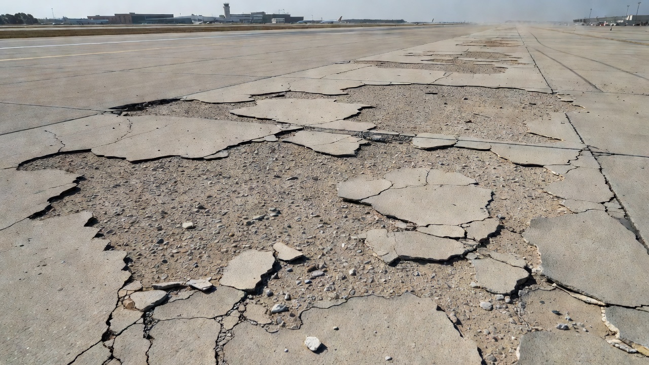
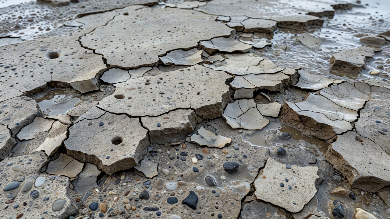
Scaling is the deterioration of the upper surface of a Portland Cement Concrete (PCC) slab, typically occurring to a depth of 3 to 13 mm (1/8 to 1/2 inch), that may appear anywhere over the pavement surface. It represents the progressive loss of surface mortar and/or aggregate that exposes underlying concrete layers, creating a rough, pitted surface texture.
The FHWA Long-Term Pavement Performance (LTPP) Distress Identification Manual (FHWA-HRT-13-092, Fifth Revised Edition, May 2014) classifies scaling as Distress Type JCP 8b for Jointed Plain Concrete Pavements, grouped under the broader category of Surface Defects (Section 2C). The official LTPP description states: “Scaling is the deterioration of the upper concrete slab surface, normally 3 to 13 mm (1/8 to 1/2 in), and may occur anywhere over the pavement.”
The LTPP manual groups map cracking and scaling together under Distress Type JCP 8, with two sub-types: JCP 8a (Map Cracking) — defined as “a series of cracks that extend only into the upper surface of the slab. Larger cracks are frequently oriented in the longitudinal direction of the pavement and are interconnected by finer transverse or random cracks” — and JCP 8b (Scaling). Map cracking frequently precedes and leads to scaling as the cracked surface layer becomes dislodged under traffic or environmental exposure. The LTPP manual does not assign severity levels to scaling (JCP 8b). Instead, the extent is the primary metric — the number of occurrences and square meters of affected area are recorded.
For Continuously Reinforced Concrete Pavements (CRCP), scaling is classified as Distress Type CRCP 4b, under Section 3B (Surface Defects) with an identical description.
The FAA PAVER™ Concrete Surfaced Airfields Distress Identification Manual (June 2009, developed by the U.S. Army Corps of Engineers ERDC-CERL) assigns scaling Distress Code 70 with the definition: “Surface deterioration caused by construction defects, material defects and environmental factors. Generally scaling is exhibited by delamination or disintegration of the slab surface to the depth of the defect.”
Scaling results from a combination of physical attack mechanisms and chemical attack mechanisms operating at the concrete surface. The FHWA guidance document Guidelines for Detection, Analysis, and Treatment of Materials-Related Distress in Concrete Pavements (FHWA-RD-01-163, March 2002) provides the most comprehensive treatment of these mechanisms.
The primary physical mechanism is freeze-thaw deterioration of the cement paste. When moist concrete is exposed to alternating cycles of freezing and thawing, internal deterioration accumulates through two governing theories. The Hydraulic Pressure Theory (Powers, 1945) holds that as ice forms in saturated capillary pores, the 9% volume expansion forces unfrozen water through the pore system. If the pore system cannot accommodate this flow due to inadequate air voids, internal hydraulic pressures exceed the tensile strength of the cement paste (approximately 2-3 MPa). The Osmotic Pressure Theory (Powers, 1975) describes how alkali concentration gradients develop as pure water freezes first in air voids, concentrating the remaining solution. Less concentrated alkaline solution migrates toward freezing sites, driving further ice accretion and generating osmotic pressures that can exceed the tensile strength of the surrounding paste.
The surface layer (“skin”) of concrete is particularly vulnerable to freeze-thaw scaling because it is composed predominantly of paste with less aggregate content, it is directly affected by finishing practices (over-working brings excess water and fines to the surface), it experiences high humidity gradients and drying shrinkage microcracking, and it is directly exposed to deicing chemicals and moisture saturation. The degree of saturation is critical — damage typically does not occur below approximately 85-90% saturation.
The application of deicing chemicals magnifies freeze-thaw damage through several mechanisms. Salt solutions are more easily absorbed into capillary pores than pure water, increasing the degree of saturation. Salt crystallization pressures develop within pores during wetting-drying cycles. Chemical degradation includes dissolution of calcium hydroxide (Ca(OH)₂) through the reaction 2NaCl + Ca(OH)₂ → CaCl₂ + 2NaOH. The most damaging chemical mechanism is the formation of hydrated calcium oxychloride (3CaO·CaCl₂·15H₂O) from calcium chloride (CaCl₂) deicers — this expansive compound forms at temperatures just above freezing (5°C to 10°C) and is highly disruptive to the concrete matrix.
The FHWA identifies several construction-related factors that predispose concrete to scaling: over-finishing (excessive troweling brings bleed water and fines to the surface, creating a weak, porous surface layer), addition of water to the surface during finishing (increases the water-cement ratio at the surface, reducing strength), insufficient hydration and poor curing (particularly in hot, dry weather or late-season placement), soft or weak surface concrete, and the use of non-air-entrained concrete in freezing environments.
{{
Air entrainment is the deliberate incorporation of microscopic air bubbles (typically 10 to 1000 μm in diameter) into the concrete, achieved through air-entraining admixtures (AEAs) added during mixing. These air voids serve as relief reservoirs during freezing. When water in capillary pores freezes and expands, the excess hydraulic pressure forces unfrozen water into the nearest air voids, where it can freeze without generating damaging pressures. The air voids also serve as collection points for osmotically driven water flow.
Per ASTM C457/C457M (Standard Test Method for Microscopical Determination of Parameters of the Air-Void System in Hardened Concrete), the critical parameters for freeze-thaw durability are:
| Parameter | Recommended Value | Description |
|---|---|---|
| Total Air Content | 6 ± 1% (by volume) | Total volume of entrained air in hardened concrete |
| Spacing Factor (L̄) | ≤ 0.20 mm (0.008 in) | Average max distance from any point in paste to nearest air void |
| Specific Surface (α) | ≥ 600 in²/in³ (24 mm²/mm³) | Surface area of air voids per unit volume of air |
| Void Frequency | ≥ 200 voids per inch (≥ 8 per mm) | Number of voids per unit length of traverse |
The Powers Spacing Factor is widely considered the most critical parameter. Powers (1949) established that regardless of total air content, if the spacing between voids exceeds 0.20 mm, water cannot reach a void before damaging pressures develop. FHWA research (FHWA-HRT-06-118) confirms that it is the air-void system in the hardened concrete, not the fresh concrete, that determines freeze-thaw resistance — loss of air content during transport and placement can reduce protection even if fresh concrete air content appears adequate.
For scaling resistance specifically, ACI 201.2R recommends: air entrainment meeting the spacing factor requirement above, maximum water-cementitious materials ratio (w/cm) of 0.45 for severe exposure, minimum 28-day compressive strength of 28 MPa (4,000 psi), proper moist curing for at least 7 days, and use of durable aggregates per ASTM C33 requirements for freeze-thaw resistance.
The FAA PAVER™ Concrete Surfaced Airfields Distress Identification Manual defines three severity levels for scaling:
| Severity | Criteria | FOD Potential | Surface Condition |
|---|---|---|---|
| Low (L) | Coarse aggregate exposed but firmly embedded; surface only slightly rough | None | Sounding solid; aggregate firmly held |
| Medium (M) | Loss of coarse aggregate to depth up to 1/4 inch (6 mm); surface moderately rough | Some | Aggregate loss to approximately 6 mm |
| High (H) | Loss of coarse aggregate to depth greater than 1/4 inch (6 mm); surface very rough | Definite | Aggregate loss > 6 mm; very rough surface |
A special case exists for low severity scaling (crazing): it is counted only if possible future scaling will occur within 2 to 3 years. If the surface texturing loss is stable and not expected to progress, it may not be recorded. This prevents over-counting of stable surface conditions that do not require repair.
A distressed slab is recorded as one slab containing scaling. If more than one severity level is found on a single slab, the slab is counted as having the higher severity distress. Critical mutual exclusivity rule: If D-cracking (Distress Code 64) is counted on a slab, scaling on the same slab should not be recorded. This prevents double-counting of freeze-thaw damage that may present with overlapping visual characteristics. If patch material is present on a scaled area of a slab, only the scaling is counted — the original distress type should be recorded rather than a patch.
In Pavement Condition Index (PCI) surveys conducted per ASTM D5340, scaling severity and density directly influence the deduct value applied to the sample unit PCI calculation. The deduct curve for scaling accounts for the density (percentage of slab area affected) and the severity level. Higher severity scaling with greater density produces higher deduct values, which reduce the calculated PCI more significantly. Scaling is an area-based distress — the extent is measured in square meters of affected surface, not linear meters as with joint distresses.
Scaling is frequently confused with other concrete surface distresses. Understanding the distinctions is essential for accurate PCI surveys and appropriate repair selection.
| Distress Type | Depth | Location | Primary Cause | LTPP Code | FAA Code |
|---|---|---|---|---|---|
| Scaling | 3–13 mm | Surface (anywhere on slab) | Freeze-thaw + deicers; poor curing/finishing | JCP 8b | 70 |
| Spalling | Variable, up to full depth | Joint/crack edges (within 0.3 m) | Incompressibles in joints; freeze-thaw; dowel misalignment | JCP 6, JCP 7 | 74, 75 |
| Delamination | Subsurface (variable) | Interior of slab (parallel to surface) | Corrosion of reinforcing steel; freeze-thaw | Not separately coded | Not separately coded |
| Popouts | 13–50 mm | Surface (isolated, 25–100 mm diameter) | Expansive aggregate particles | JCP 10 | 68 |
| Map Cracking | Surface only (≤ 3 mm) | Anywhere on slab surface | Improper curing; finishing; ASR | JCP 8a | (with scaling) |
| D-Cracking | Full depth at joints | Along joints/cracks (0.3–0.6 m zone) | Aggregate freeze-thaw susceptibility | JCP 2 | 64 |
Scaling vs. Spalling: Scaling affects the general slab surface and is shallow (typically < 13 mm). Spalling is specifically at joints or cracks, extends from the joint face inward, and involves cracking/chipping/fraying of the slab edge. Spalling has separate FAA PAVER codes (74 for joint spalling, 75 for corner spalling) and LTPP codes (JCP 6 for longitudinal joint spalling, JCP 7 for transverse joint spalling).
Scaling vs. Delamination: Delamination is a subsurface horizontal separation within the concrete that may not be visible on the surface. It is detected by “sounding” — a dull response from a hammer or chain indicates delamination. When delaminated surface concrete breaks away, it may present similarly to scaling but typically involves a larger depth and area.
Scaling vs. Popouts: Popouts are individual, localized spalls (25–100 mm diameter, 13–50 mm depth) caused by expansive aggregates such as reactive chert, pyrite, or shale particles. Popouts must exceed a density of approximately 3 per square meter before being counted as a distress per FAA PAVER. Scaling affects continuous areas, not isolated spots.
Scaling vs. D-Cracking: D-cracking (Durability Cracking, LTPP JCP 2) originates from aggregate freeze-thaw susceptibility rather than paste deterioration, and is characterized by closely spaced crescent-shaped hairline cracks adjacent to joints with a dark coloring pattern. D-cracking initiates at the bottom of the slab or at joint edges and propagates upward and inward. The FAA PAVER manual mandates mutual exclusivity — D-cracking and scaling are not recorded on the same slab.
This is the primary standard test method for evaluating scaling resistance. Concrete test specimens (300 × 300 × 75 mm panels) are cast and cured for 14 days per ASTM C192. A 6 mm deep pond of deicing solution (typically 4% CaCl₂ or NaCl) is placed on the surface. Specimens undergo freeze-thaw cycling — one cycle consists of 16–18 hours freezing at −18°C ± 2°C followed by 6–8 hours thawing at 23°C ± 2°C. After every 5 cycles, the surface is visually examined and rated:
| Rating | Condition of Surface |
|---|---|
| 0 | No scaling |
| 1 | Very slight scaling (≤ 3 mm depth, no coarse aggregate visible) |
| 2 | Slight to moderate scaling |
| 3 | Moderate scaling (some exposure of coarse aggregate) |
| 4 | Moderate to severe scaling (coarse aggregate exposed throughout) |
| 5 | Severe scaling (coarse aggregate exposed over entire surface, loss of surface mortar) |
The test is typically continued through 25 to 50 cycles, or until a rating of 3 or higher is reached. This is a qualitative test method — results are based on visual examination. It evaluates the effectiveness of air entrainment, curing adequacy, concrete mixture proportions (w/cm ratio), supplementary cementitious materials, and deicing chemical type and concentration.
This standard measures overall freeze-thaw durability through quantitative methods. Concrete prism specimens (75 × 100 × 400 mm) are subjected to repeated freezing and thawing in water (Procedure A) or air (Procedure B). The primary measurement is Relative Dynamic Modulus (RDM) — concrete is considered freeze-thaw durable if RDM remains ≥ 80% of the initial value after 300 cycles. The Durability Factor (DF) = (P × N) / M, where P = RDM at N cycles (%), N = number of cycles at which P reaches 60% or specified termination, and M = total number of cycles specified (typically 300).
| Standard | Relevance to Scaling |
|---|---|
| ASTM C457/C457M | Quantifies air-void system parameters (spacing factor, specific surface, air content) in hardened concrete |
| ASTM C260/C260M | Specification for air-entraining admixtures for concrete |
| ASTM C233/C233M | Test method for air-entraining admixture performance |
| ASTM C31/C31M | Procedures for making and curing concrete test specimens in the field |
Per FAA Advisory Circular AC 150/5380-6C (Guidelines and Procedures for Maintenance of Airport Pavements, October 2014) and FHWA guidance on partial-depth repair, the treatment approach depends on scaling severity and extent.
| Scaling Severity | Recommended Action | Timing |
|---|---|---|
| Low (surface texture loss only) | Monitor; no immediate repair needed | Routine inspection cycle |
| Low to Medium (exposed aggregate, < 6 mm depth) | Partial-depth patch (PDR) if limited area; surface treatment if extensive | Within 1–2 years |
| Medium to High (> 6 mm depth, aggregate loss) | PDR if confined to upper 1/3 slab; consider full-depth if deeper | ASAP (within 6 months) |
| High (extensive area, deep scaling) | Overlay (PCC or asphalt) or slab replacement | Urgent (within 3 months) |
| Scaling with structural distress | Full-depth repair or slab replacement | Immediate |
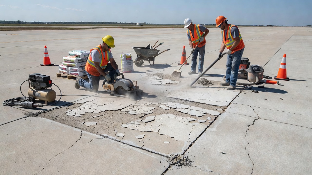
Partial-depth repair (PDR) is the standard treatment for scaling confined to the upper one-third of the slab thickness. The procedure per FAA and FHWA guidance: Identify deteriorated concrete by sounding (hammer or chain — dull sound indicates deteriorated concrete). Mark repair boundaries with brightly colored spray paint — boundaries should be square or rectangular with minimum dimensions of 300 mm (12 in) length and 100 mm (4 in) width. Saw cut boundaries with a diamond-bladed saw to a depth matching the repair depth. Remove deteriorated concrete using light pneumatic hammers (< 13.5 kg / 30 lb), starting at the center and working toward edges, using spade bits at a 45° angle to avoid damaging sound concrete at the perimeter. Depth must be ≤ 1/3 of slab thickness; if dowel bars are exposed, switch to full-depth repair. Clean the cavity by sandblasting or high-pressure water. Apply bonding agent if required by the repair material specification. Place repair material — normal concrete (Type I/II/III Portland cement) for repairs with > 24-hour cure time, or rapid-set materials (magnesium phosphate, polymer concrete) where early opening is needed. Cure properly — wet curing for minimum 3 days for cementitious materials. Saw and seal joints to restore the joint sealant system.
{{
For large-area scaling where individual patching is impractical, surface treatments include diamond grinding (removes 3–6 mm surface layer to restore smoothness and texture — suitable for low severity, uniform scaling), thin bonded concrete overlay (25–50 mm PCC overlay bonded to prepared surface — suitable for medium severity, large areas), asphalt overlay (HMA overlay with reflective crack control — for scaling with other distresses), and polymer or micro-surfacing (thin surface treatment for low severity, primarily functional improvement).
Full-depth repair is required when scaling extends below the top one-third of the slab, structural cracking accompanies scaling, multiple distresses exist in the same slab, or dowel bars are exposed or corroded. The procedure per FAA AC 150/5380-6C Appendix A involves full slab removal, base and subgrade preparation, dowel bar retrofitting (if at joints), PCC replacement with appropriate joint restoration.
ICAO Annex 14, Volume I (8th Edition, July 2018, incorporating Amendment 14) does not specifically name “concrete scaling” in its Standards and Recommended Practices (SARPs). However, three SARPs directly apply to scaling-damaged surfaces. Standard 10.2.3 requires: “A paved runway shall be maintained in a condition so as to provide surface friction characteristics at or above the minimum friction level specified by the State.” Standard 10.2.5 requires: “A paved runway shall be maintained free of loose stones or other objects that could cause damage to an aeroplane structure or to the engines of an aeroplane.” Standard 10.2.6 requires: “The surface of a paved runway, including shoulders, shall be maintained so as to prevent the formation of harmful irregularities.”
The ICAO Aerodrome Design Manual (Doc 9157, Part 3 — Pavements) provides technical guidance on pavement evaluation and maintenance, including surface distress identification. For international aerodromes, scaling that creates FOD or reduces friction below State-specified minimum levels constitutes a non-compliance with Annex 14, requiring corrective maintenance under the aerodrome’s maintenance program. This is particularly critical for runway end safety areas, touchdown zones, and high-speed turnoffs where maximum friction is required.
The FAA AC 150/5380-6C (Guidelines and Procedures for Maintenance of Airport Pavements, October 2014) provides the primary FAA guidance on identifying and addressing scaling. Chapter 3 classifies rigid pavement distresses into categories including surface distress. Table 6-2 (Quick Guide for Maintenance and Repair of Common Rigid Pavement Surface Problems) lists scaling as a surface problem with cause factors including freeze-thaw action, deicing chemicals, and improper finishing/curing, with recommended repair methods of partial-depth patch (if < 1/3 slab depth), surface treatment, or full-depth patch (if extensive). The AC incorporates the FAA PAVER distress identification system and references ASTM D5340 for PCI survey methodology.
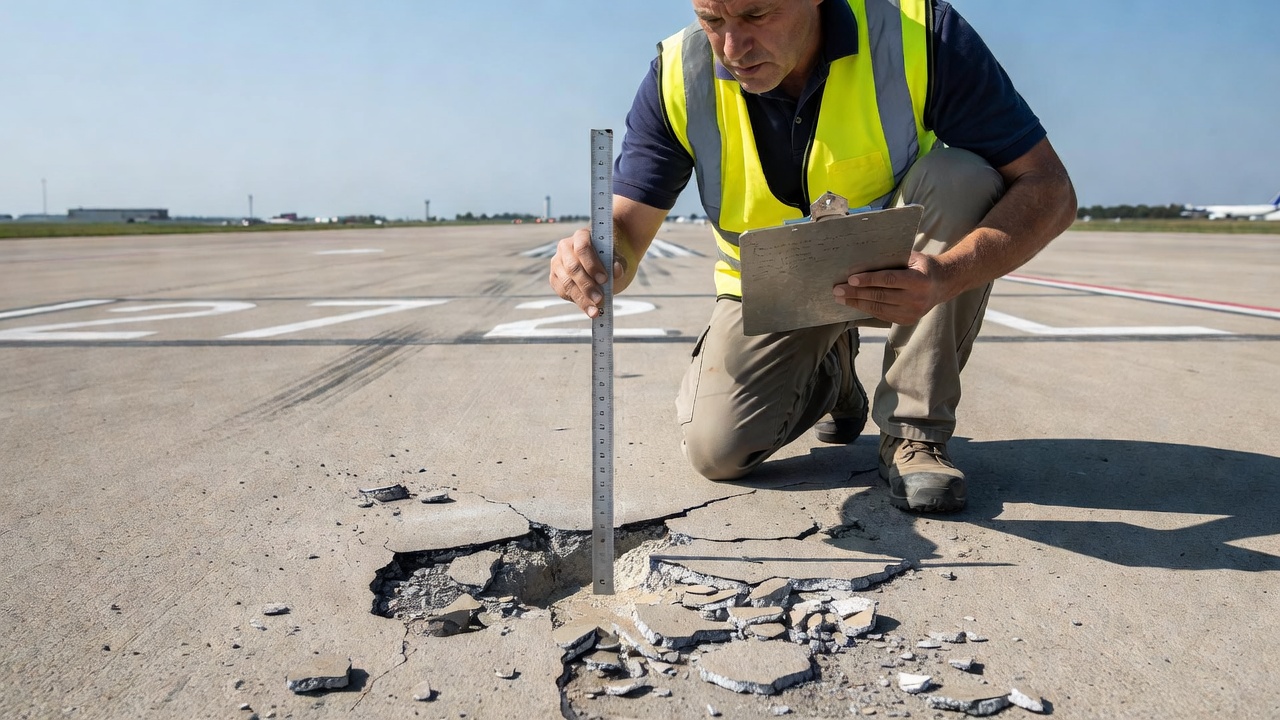
During visual inspection of scaling in PCI surveys per ASTM D5340, the inspector records the following parameters per sample unit. Extent is measured as the surface area affected in square meters — if multiple non-contiguous areas of scaling exist, the total area is summed. Severity is assessed per FAA PAVER criteria (low, medium, high based on aggregate loss depth and surface roughness). Slab count — each slab containing scaling is recorded.
{{
The inspection must also check for associated distresses — map cracking (JCP 8a) frequently accompanies scaling and may be a precursor. If D-cracking (JCP 2) is present, scaling is not separately recorded per FAA PAVER mutual exclusivity rules. The presence of patch material on a scaled area is documented as scaling only (the original distress type per manual guidance). The foreign object debris (FOD) potential is assessed qualitatively based on severity — medium severity has “some” FOD potential and high severity has “definite” FOD potential, per the FAA PAVER manual.
Scaling is a critical performance indicator in airport pavement management systems (APMS). The presence and severity of scaling directly influence:
Pavement Condition Index (PCI) — scaling deduct values reduce the calculated PCI, triggering maintenance and rehabilitation prioritization. A single slab with high severity scaling over 50% of its area can produce a deduct value of 40–60 points, significantly reducing the sample unit PCI.
Surface Friction Characteristics — scaling exposes coarse aggregate and creates surface roughness that alters macrotexture. Per ICAO Annex 14 Standard 10.2.3, friction must remain above State-specified minimum levels. Runways with scaling in the touchdown zone require more frequent friction testing (continuous friction measuring equipment per ICAO Doc 9137).
FOD Prevention Programs — per FAA AC 150/5210-24 (Airport Foreign Object Debris Management), medium and high severity scaling on runways, taxiways, and aprons requires active FOD monitoring and timely repair. Exposed aggregate particles at medium and high severity levels can become dislodged under aircraft tire loading and be ingested into engines or damage tires.
Structural Life Prediction — progressive scaling reduces the effective slab thickness over time. While the structural implications of 3–13 mm of surface loss are minimal for 300–450 mm thick airport pavement slabs, scaling that progresses to expose dowel bars at joints (typically at 75–100 mm depth) requires immediate full-depth repair to prevent joint load transfer failure.
| Parameter | Value | Standard/Source |
|---|---|---|
| Scaling depth range | 3–13 mm (1/8–1/2 in) | FHWA LTPP DIM (FHWA-HRT-13-092) |
| FAA PAVER Code | 70 | FAA PAVER Distress Manual |
| Medium severity depth threshold | 1/4 in (6 mm) | FAA PAVER Manual |
| High severity depth threshold | > 1/4 in (> 6 mm) | FAA PAVER Manual |
| Air content (entrained) | 6 ± 1% by volume | ASTM C457 |
| Maximum spacing factor | 0.20 mm (0.008 in) | ASTM C457 / ACI 201.2R |
| Maximum w/cm for severe exposure | 0.45 | ACI 201.2R |
| Minimum moist curing duration | 7 days | ACI 308 |
| Minimum 28-day compressive strength | 28 MPa (4,000 psi) | ACI 201.2R |
| ASTM C672 maximum rating before failure | 3 (moderate scaling) | ASTM C672 |
| ASTM C666 minimum RDM after 300 cycles | 80% | ASTM C666 |
| Partial-depth repair max depth | 1/3 slab thickness | FAA AC 150/5380-6C |
| Spacing factor critical threshold | 0.20 mm | Powers (1949) / FHWA-RD-01-163 |
| Emergency patch max service life | 6 months | FAA AC 150/5380-6C |
| Low severity scaling projection period | 2–3 years | FAA PAVER Frequently Occurring Problems |
TarmacView provides automated detection and classification of concrete scaling distress from visual and thermal data. Streamline your PCI surveys, generate accurate reports, and prioritize repairs for airfield and highway pavements.
Map cracking (also called crazing) is a network of shallow, fine, interconnected cracks on the concrete surface forming an irregular pattern. In FHWA LTPP, map ...
Joint spalling is the cracking, breaking, or chipping of concrete slab edges at transverse or longitudinal joints in PCC pavements. It occurs when incompressibl...
Spalling is the breaking, chipping, or loss of concrete material at pavement joints, edges, or cracks — a critical defect in airport runways, taxiways, bridges,...