Spalling
Spalling is the breaking, chipping, or loss of concrete material at pavement joints, edges, or cracks — a critical defect in airport runways, taxiways, bridges,...
26 min read
Pavement Defects
Airport Inspection
+1
A shattered slab is a portland cement concrete (PCC) pavement slab broken into four or more pieces by intersecting cracks, representing the terminal structural distress condition for rigid pavements. It requires full-depth slab replacement. Covers FAA PAVER (Distress 72), FHWA LTPP, TxDOT PMIS classification, causes including overloading and ASR, detection methods, and FOD implications for airport runways.
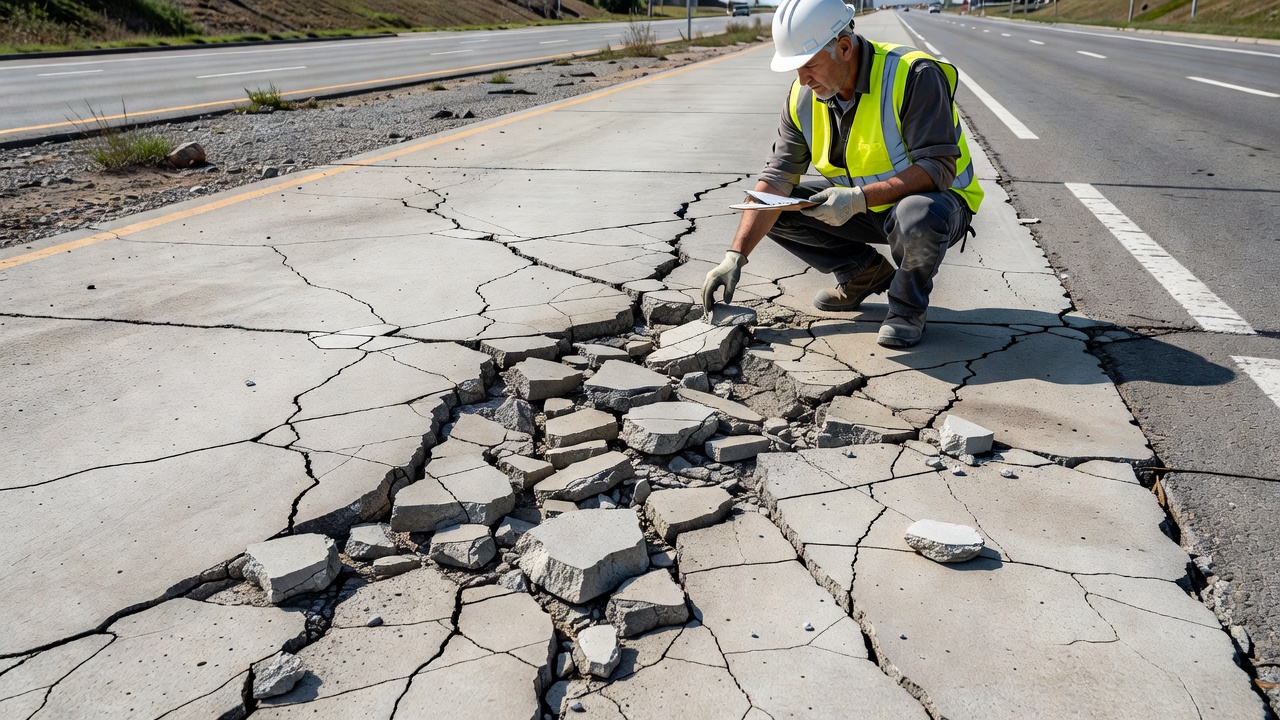
A shattered slab is a portland cement concrete (PCC) pavement slab that has been broken into four or more distinct pieces by a network of intersecting cracks. This condition represents the terminal structural failure stage for a rigid pavement slab — the point at which the slab has completely lost its ability to function as a load-distributing structural element. The FAA PAVER™ distress identification system classifies shattered slab as Distress Type 72 (Shattered Slab/Intersecting Cracks) under the concrete-surfaced airfields distress manual published by the US Army Corps of Engineers ERDC-CERL. In the PAVER system, the high-severity level of intersecting cracks (classified under the Cracks distress, Type 63) is explicitly referred to as a shattered slab.
The visual appearance of a shattered slab is unmistakable. The slab surface is divided by a network of interconnected cracks that create a polygonal fracture pattern with four or more individual concrete fragments. These fragments may range in size from small pieces less than 0.5 m (1.5 ft) across to larger segments several feet in dimension. The cracks typically intersect at various angles, creating an irregular mosaic or block pattern across the entire slab area. In advanced cases, individual pieces become displaced vertically relative to each other (faulting), and fragments may become loose and detach from the slab entirely.
The Oregon Department of Transportation (ODOT) Pavement Data Collection Manual (Revised March 2022) defines a shattered slab as a concrete slab broken into four or more pieces, consistent with the Concrete Surfaced Airfields PAVER™ Distress Identification Manual. ODOT clarifies that a slab containing a shattered slab condition cannot simultaneously be counted as having transverse cracking — the rater must classify the slab under the shattered slab distress type only. This is an important distinction for pavement management data collection where double-counting of distresses could skew condition indices.
The TxDOT Pavement Management Information System (PMIS) Rater’s Manual (Fiscal Year 2024) further elaborates that a shattered slab is counted per individual slab, with a maximum count of 24 slabs per data collection section or the total number of slabs in the section, whichever is less. TxDOT emphasizes that shattered slabs cannot also be counted as Failed Joints and Cracks (FJC) — the rater must select the most appropriate classification for each slab.
Key distinction: For a slab to be classified as shattered, the intersecting cracks must divide the slab into four or more pieces. A slab divided into only two or three pieces is classified as having longitudinal, transverse, or diagonal cracking (PAVER Distress 63), not as a shattered slab. The threshold of four pieces is the universal standard across FAA, FHWA, TxDOT, and ASTM pavement distress identification protocols.
| Distress Type | Number of Pieces | PAVER Code | Repair Method |
|---|---|---|---|
| Crack (L/T/D) | 2-3 pieces | 63 | Crack sealing, routing, or partial patch |
| Corner Break | 1 corner piece separated | 62 | Full-depth or partial-depth patch |
| Shattered Slab | 4 or more pieces | 72 | Full slab replacement |
The FAA PAVER™ system and the Unified Facilities Criteria (UFC 3-270-05) define three severity levels for shattered slabs based on crack width, spalling condition, and foreign object debris (FOD) potential.
Low Severity (L): The slab is divided into four or more pieces, but the cracks have no spalling or only minor spalling with no FOD potential. Non-filled cracks have a mean width less than approximately 1/8 inch (3 mm). Filled cracks can be of any width but the filler material must be in satisfactory condition. At this severity level, the slab pieces are still tightly interlocked with good aggregate interlock providing some load transfer. The slab may still carry limited traffic loads but has significantly reduced structural capacity.
Medium Severity (M): One or more of the following conditions exist: filled or non-filled cracks are moderately spalled with some FOD potential; non-filled cracks have a mean width between 1/8 inch (3 mm) and 1 inch (25 mm); filled cracks have no spalling or only minor spalling, but the filler is in unsatisfactory condition (debonded, hardened, or oxidized). At medium severity, aggregate interlock is partially lost, faulting may be present, and the slab pieces move independently under load. Water infiltration through open cracks accelerates subgrade softening and pumping.
High Severity (H): One or more of the following conditions exist: filled or non-filled cracks are severely spalled with definite FOD potential; non-filled cracks have a mean width greater than approximately 1 inch (25 mm), creating tire damage potential; the slab pieces are loose and can be displaced under traffic. The high-severity level of intersecting cracks is explicitly defined as a shattered slab in the PAVER system. At this severity, the slab has completely failed structurally and poses an immediate safety hazard. On airport pavements, high-severity shattered slabs present a critical FOD hazard requiring immediate attention.
The UFC 3-270-05 PAVER manual provides a critical rule in its Frequently Occurring Problems table: when medium or high severity intersecting cracks (shattered slab) are present on a slab, no other distress should be counted for that slab. This rule reflects the fact that a shattered slab has reached the terminal failure condition — all other distress types (spalling, joint damage, pumping, etc.) become irrelevant because the slab must be fully replaced regardless of any other defects present.
Shattered slabs result from a combination of structural, material, and environmental factors acting singly or in concert. Understanding these causes is essential for designing preventive strategies and identifying the root failure mechanism during forensic pavement investigations.
Repeated application of heavy traffic loads is the most common cause of slab shattering in highway applications. Concrete pavements are designed for a specific number of load repetitions over their service life. When actual traffic loads exceed design assumptions — either through increased traffic volume or heavier axle loads — the slab experiences fatigue damage that accumulates over time. The fatigue life of a PCC slab follows the classical Wöhler (S-N) relationship where the number of cycles to failure decreases exponentially as the applied stress level increases. A slab designed for 10 million equivalent single axle loads (ESALs) over 20 years may fail in under 5 million cycles if actual loads are 20-30% higher than design values.
Fatigue cracking initiates at the bottom of the slab (tension side) where tensile stresses are highest under wheel loads at the slab edge or corner. The cracks propagate upward through the slab thickness. Once a crack reaches the surface, water infiltration and load-induced pumping accelerate the deterioration. With continued loading, additional cracks form and interconnect, eventually dividing the slab into four or more pieces.
Loss of foundation support is a primary contributing factor to slab shattering. When voids develop beneath the slab — typically from pumping, subgrade erosion, or consolidation — the unsupported portion of the slab can no longer transfer loads to the base. The slab then acts as a cantilever or plate spanning over the void, generating tensile stresses far exceeding those in a fully supported slab.
Pumping is the ejection of water and fine material through joints or cracks under the action of passing traffic loads. As water is ejected, it carries particles of subgrade or base material, progressively creating voids beneath the slab. Surface staining and base material deposits on the pavement surface near joints or cracks are evidence of pumping. Per the FAA PAVER manual, the joint seal must be identified as defective before pumping can be said to exist. Pumping can occur at cracks as well as joints. Each pumping joint between two slabs is counted as two affected slabs.
Subgrade erosion occurs when water accumulates beneath the pavement and the cyclic deflection from traffic loads pumps out fines, creating a progressive void. In poorly draining subgrades (AASHTO classification A-6 or A-7 clays), the erosion rate can accelerate during wet seasons when subgrade moisture content increases and shear strength decreases.
Alkali-silica reaction is a chemical deterioration mechanism that can cause progressive slab deterioration leading to shattering. ASR occurs when the high pH of the concrete pore solution (due to alkalis Na2O and K2O present in cement) reacts with reactive silica in certain aggregates. The reaction produces an expansive alkali-silica gel that absorbs water and swells, generating internal tensile stresses within the concrete. These internal expansion stresses can exceed 3-5 MPa (435-725 psi), which is at or above the tensile strength of typical pavement concrete (3-4 MPa or 435-580 psi).
ASR-damaged concrete exhibits a characteristic map cracking or pattern cracking on the surface, with cracks following the boundaries of coarse aggregate particles. The FHWA Alkali-Silica Reactivity Field Identification Handbook (FHWA-HIF-12-022) documents that ASR-affected pavements show joint closure due to overall slab expansion, surface discoloration (darkening), gel exudation at cracks and joints (clear to yellowish or white deposits), and popouts where reactive aggregate particles have expanded and broken the surface. Over time, the ASR-weakened concrete loses tensile strength and fracture toughness, making it highly susceptible to traffic-induced shattering. ASR is distress code 76 in the PAVER system.
Durability cracking, also known as D-cracking, is caused by the inability of the concrete to withstand freeze-thaw cycles. It typically appears as a pattern of fine parallel cracks running adjacent to joints, edges, and cracks. A dark coloration is usually visible around the fine D-cracks. This type of cracking may eventually lead to complete disintegration of the concrete within 0.3 to 0.6 meters (1 to 2 feet) of the joint or crack.
D-cracking results from hydraulic pressure generated when water in the aggregate pores freezes and expands. Certain aggregates with high absorption and poor freeze-thaw resistance are particularly susceptible. As D-cracking progresses, the concrete near joints and cracks becomes weakened and disintegrated, creating localized zones of structural weakness. Under repeated traffic loading, these weakened zones can act as initiation points for the intersecting cracks that eventually divide the slab into four or more pieces. D-cracking is distress code 64 in the PAVER system.
Temperature and moisture gradients through the slab thickness cause the slab to curl or warp. During daytime, the slab surface is warmer than the bottom, causing the slab to curl downward at the edges and corners. At night, the surface cools more rapidly, causing the slab to curl upward. These curling stresses, when combined with wheel loads, can generate tensile stresses at the slab surface (nighttime) or bottom (daytime) that exceed the concrete’s tensile strength. Repeated curling cycles (diurnal temperature cycling) induce fatigue damage that, over time, can initiate and propagate cracks. When multiple curling-induced cracks intersect with load-induced cracks or material-related cracks, the slab can become shattered.
Delayed ettringite formation is a relatively rare but severe concrete deterioration mechanism that occurs when concrete is subjected to high temperatures during curing (typically above 70°C or 158°F) in mass concrete sections. The high temperature prevents the normal formation of ettringite during the early hydration phase. Later, when the concrete cools and is exposed to moisture, ettringite forms belatedly, causing internal expansion and cracking. DEF produces a characteristic cracking pattern similar to ASR but without gel formation, and can lead to complete disintegration and slab shattering if not addressed.
| Category | Causes | Repair Options |
|---|---|---|
| Block Rejuvenation | 9-18 months | Removes 1-2 years of aging |
| Semi-Annual | 6 months | Track record of 6 to 18 months |
The classification of shattered slabs differs notably between the FHWA Long-Term Pavement Performance (LTPP) program and state-level pavement management systems like TxDOT PMIS and ODOT.
Interestingly, the FHWA LTPP Distress Identification Manual (FHWA-HRT-13-092, Fifth Revised Edition, May 2014) does not include shattered slab as a separate distress type for jointed PCC pavements. The LTPP manual classifies all cracking in JCP under three distress types: Corner Breaks (JCP-1), Longitudinal Cracking (JCP-3), and Transverse Cracking (JCP-4). A slab with multiple intersecting cracks would be recorded in the LTPP system by counting each individual crack under the appropriate longitudinal or transverse cracking category rather than as a discrete shattered slab distress.
The Oregon ODOT Pavement Data Collection Manual explicitly notes this difference: “Shattered Slabs – Updated language regarding number of pieces and severity level to be consistent with PAVER protocol; not an LTPP distress type.” This means that agencies using the LTPP protocol for FHWA reporting must extrapolate shattered slab counts from the individual crack data, while agencies using the PAVER or state-specific systems can record shattered slabs as a discrete distress type.
The TxDOT PMIS system treats shattered slabs as a stand-alone distress type within its Jointed Concrete Pavement (JCP) classification. The PMIS Rater’s Manual (FY 2024) specifies:
TxDOT also identifies slab shattering as one of the distress types that require full-depth repair (FDR) in concrete pavement contraction design (CPCD). The TxDOT Full-Depth Repair manual states: “In concrete pavement contraction design (CPCD), the following distresses require FDR: transverse cracks, shattered slabs and corner breaks.”
The Oregon ODOT system classifies shattered slabs under Section 3 (Jointed Concrete Pavements) of their Pavement Data Collection Manual. Key specifications include:
Differentiating shattered slabs from punchouts and corner breaks is essential for accurate pavement condition assessment. Each distress type occurs under different pavement configurations and failure mechanisms, and each requires different repair strategies.
| Distress | Pavement Type | Pieces | Cause | Repair |
|---|---|---|---|---|
| Corner Break (PAVER 62) | JCP | 1 corner piece separated | Load + loss of support + curling | Full-depth corner patch |
| Shattered Slab (PAVER 72) | JCP | 4+ pieces | Overload, ASR, loss of support | Full slab replacement |
| Punchout (LTPP CRCP-12) | CRCP | Localized area between 2 transverse cracks | Loss of load transfer + support | Full-depth patch |
A corner break is a crack that intersects the two adjacent joints of a slab at distances less than or equal to one-half the slab length on both sides, measured from the corner of the slab. For example, a slab measuring 25 by 25 feet (7.5 by 7.5 m) with a crack intersecting the joint 5 feet (1.5 m) from the corner on one side and 17 feet (5 m) on the other side is not a corner break — it is a diagonal crack. However, a crack intersecting at 7 feet (2 m) on one side and 10 feet (3 m) on the other is a corner break. A corner break differs from a corner spall in that the crack extends vertically through the entire slab thickness, while a corner spall intersects the joint at an angle.
A punchout is a distress specific to Continuously Reinforced Concrete Pavement (CRCP) . The TxDOT PMIS manual defines a punchout as occurring in CRCP when there is a closely spaced transverse crack pattern (typically with characteristic “Y-cracks”) combined with longitudinal cracking, creating a small, localized failed area bounded by two transverse cracks and the longitudinal crack or joint. A punchout essentially represents a localized structural failure of the CRCP slab where the reinforcement has lost its ability to hold cracks tightly closed, and the concrete has broken into pieces.
The key difference from a shattered slab is pavement type: punchouts occur exclusively in CRCP (where slabs are not separated by joints and are connected by continuous longitudinal reinforcement), while shattered slabs occur in JCP (where each slab is individually defined by joints). A punchout is also typically smaller in area than a shattered slab, affecting only a localized portion of the pavement rather than an entire slab.
| Characteristic | Shattered Slab (JCP) | Punchout (CRCP) |
|---|---|---|
| Pavement Type | Jointed Concrete Pavement | Continuously Reinforced Concrete Pavement |
| Area Affected | Entire slab | Localized area (typically 1-3 m²) |
| Boundaries | Joints define slab perimeter | Two transverse cracks + longitudinal crack/joint |
| Required Pieces | 4 or more pieces | A failed area (can be 2+ pieces) |
| TxDOT Classification | JCP Shattered Slab | CRCP Failure/Punchout |
A shattered slab severely degrades ride quality. At low severity, the slab pieces may still be relatively stable with minimal vertical displacement, creating a tolerable but noticeably rough ride. At medium severity, faulting between adjacent pieces of 3-10 mm (1/8 to 3/8 inch) creates jarring impacts as vehicle tires cross crack boundaries. At high severity, differential vertical movement between pieces can exceed 13 mm (1/2 inch), creating a hazardous driving surface. On highways, this degradation in ride quality translates to increased vehicle operating costs, driver discomfort, and potential loss of vehicle control. The International Roughness Index (IRI) for a section containing multiple shattered slabs can exceed 300-400 inches/mile, compared to 50-100 inches/mile for a smooth PCC surface.
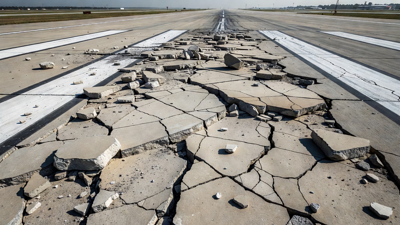
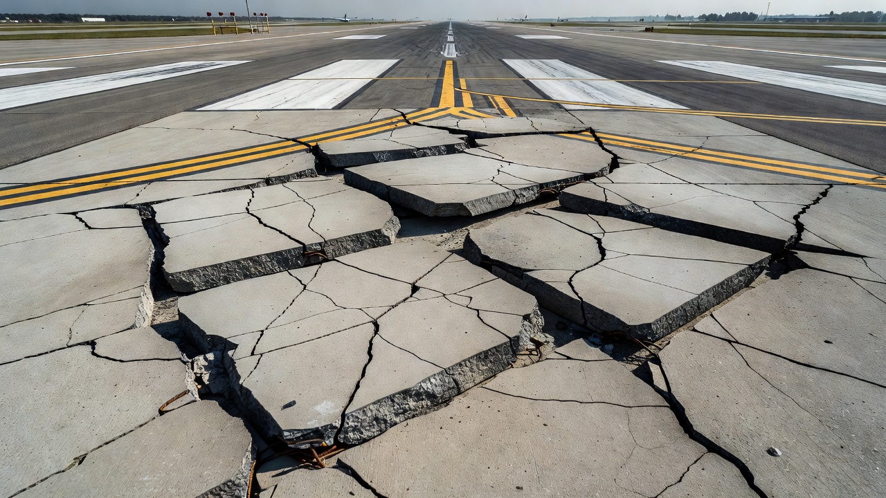
On airport pavements, shattered slabs represent one of the most critical Foreign Object Debris (FOD) hazards. When concrete pieces become loose — as occurs at medium and high severity levels — they can be dislodged by aircraft tires, jet blast (exhaust velocities up to 200 knots at full thrust), propeller wash, or wind. These fragments on runways, taxiways, and aprons can:
The ACRP Report 159 Field Guide for Airport Pavement Maintenance identifies shattered slab/intersecting cracks as requiring immediate full-depth repair when FOD potential exists. The FAA Advisory Circular 150/5380-7B emphasizes that airport operators must conduct regular FOD inspections and prioritize repair of deteriorated pavement that could generate debris.
A shattered slab has completely lost its structural capacity. The key structural functions of a concrete pavement slab — load distribution, stress reduction at the subgrade level, and load transfer at joints — are all compromised. The multiple cracks prevent any meaningful load distribution because the slab no longer acts as a continuous structural element. Each individual piece responds independently to applied loads, concentrating stress at the subgrade level and accelerating subgrade rutting or erosion.
For jointed concrete pavements, a shattered slab also compromises load transfer to adjacent slabs. The dowel bars at transverse joints may become disengaged from the shattered slab, reducing joint efficiency from 80-95% in sound slabs to below 20-30% at joints adjacent to shattered slabs. This creates a cascading deterioration effect where adjacent sound slabs experience higher edge stresses and become more susceptible to cracking and eventual shattering.
Manual visual inspection remains the most common method for identifying shattered slabs. Inspectors walk the pavement section and visually assess each slab for intersecting cracks dividing it into four or more pieces. The inspection procedure per ASTM D5340 (Standard Test Method for Airfield Pavement Condition Index Surveys) involves:
The TxDOT PMIS manual provides specific guidance for inspectors: a slab with four or more pieces from intersecting cracks is counted as one shattered slab. The rater must ensure the slab is not also counted as having transverse cracking or failed joints.
Modern pavement inspection programs increasingly use automated methods for shattered slab detection. High-resolution line-scan cameras mounted on data collection vehicles capture continuous 360° pavement surface images at speeds up to 60 mph (97 km/h). These images are then processed using computer vision algorithms to detect intersecting crack patterns characteristic of shattered slabs.
The Oregon ODOT manual specifies that automated data collection is the primary survey method, but manual verification from Right of Way images may be needed where cracks are not clearly visible in automated imagery. ODOT notes that “fine longitudinal cracks that are not visible in the Right of Way image should not be rated,” establishing a practical threshold for automated detection.
Machine learning models trained on labeled PCC distress data can identify shattered slabs with accuracy exceeding 85-90% under favorable conditions. However, the models must be trained to distinguish shattered slabs (4+ pieces) from slabs with multiple non-intersecting cracks or slabs with separate joint damage. The distinction is subtle but critical for accurate pavement condition assessment.
Ground-penetrating radar (GPR) can detect loss of support beneath slabs — a key precursor to shattering. GPR surveys at 1-2 GHz frequencies can identify voids and debonding at the slab-base interface to depths of 500-750 mm (20-30 inches). When systematic loss of support is detected across multiple adjacent slabs, the pavement section is at elevated risk for future shattered slab development.
The FAA recommends airport pavement condition surveys at intervals of 2-5 years depending on traffic levels and pavement age. For pavements in Poor condition (PCI below 55), annual surveys are recommended. The TxDOT PMIS survey is conducted annually for all state-maintained highways. For highways with known shattered slab issues, more frequent monitoring (quarterly or semi-annual) may be warranted to track deterioration rates and prioritize repairs.
Full-depth slab replacement is the only acceptable repair method for a shattered slab. The slab has failed structurally through its entire thickness, and no surface treatment, crack sealing, or overlay can restore its structural capacity. The full-depth repair procedure per FAA AC 150/5370-10H and industry standard practices includes:
Step 1 — Saw Cutting: The slab boundaries are saw-cut at the existing joints or at least 0.6 m (2 ft) beyond all visible cracks. This ensures all cracked and deteriorated concrete is removed. The saw cuts should extend through the full slab thickness.
Step 2 — Slab Removal: The entire slab is removed using hydraulic breakers or lifting equipment. All reinforcement, dowel bars, and tie bars within the slab are cut and removed. Care must be taken not to damage adjacent sound slabs during removal.
Step 3 — Base Preparation: The exposed base course is inspected and repaired as needed. Any soft or eroded base material is removed and replaced with compacted aggregate base or lean concrete base. The base is compacted to 100% of modified Proctor density. A thin layer of sand (13-25 mm or 0.5-1 inch) may be placed as a leveling course for the new concrete.
Step 4 — Dowel Bar Installation: New dowel bars (typically 32-38 mm or 1.25-1.5 inch diameter smooth steel bars, 460 mm or 18 inches long) are installed at transverse joints. Holes are drilled into the existing adjacent slabs using template-guided drills to ensure proper alignment (parallel to the pavement surface and centerline). The bars are epoxy-grouted into place to achieve full bond. Tie bars (13-16 mm or #4-#5 deformed bars) are installed at longitudinal joints.
Step 5 — Concrete Placement: New PCC concrete is placed using a mix design matching or exceeding the existing pavement strength. Typical specifications require 28-day compressive strength of 24-35 MPa (3,500-5,000 psi), flexural strength of 4.5-5.5 MPa (650-800 psi) at 28 days (third-point loading), and a maximum water-cement ratio of 0.45-0.50. Air entrainment of 5-8% is required for freeze-thaw resistance. The concrete is consolidated by internal vibration to eliminate voids.
Step 6 — Curing: The new concrete is cured using wet burlap, curing compound (membrane-forming, white-pigmented), or wet cover for a minimum of 7 days (or until reaching 70% of design strength). Temperature and moisture control during curing are critical to prevent plastic shrinkage cracking.
Step 7 — Joint Sawing: New contraction joints are sawed at spacings matching the existing pavement joint pattern (typically 4.6-6.1 m or 15-20 ft). Joints are sawed as soon as the concrete has gained sufficient strength to prevent raveling (typically 4-12 hours after placement) to control random cracking.
Step 8 — Joint Sealing: After curing and cleaning, the joints are sealed with hot-poured or cold-applied joint sealant to prevent water infiltration and incompressible material accumulation.
| Repair Method | Applicability | Cost | Service Life |
|---|---|---|---|
| Crack sealing | Pre-shattering cracks | Low | 2-5 years |
| Partial-depth patch | Surface spalling only | Moderate | 3-7 years |
| Full-depth patch | Corner breaks, localized failure | Moderate-High | 5-10 years |
| Full slab replacement | Shattered slabs | High | 10-20 years |
| Concrete overlay | Widespread deterioration | Very High | 15-25 years |
Some pavement managers consider asphalt or concrete overlay as a lower-cost alternative to slab replacement for shattered slabs. This approach is structurally inadequate because the overlay cannot prevent independent movement of the shattered slab fragments. The fragments continue to move under traffic loads, reflecting cracks through the overlay within 1-3 years. On airport pavements, reflective cracking through overlays over shattered slabs can occur within months, rapidly recreating the FOD hazard. The FAA and FHWA guidance documents uniformly specify that slabs must be structurally sound before overlay placement — shattered slabs must be replaced, not overlaid.
Airport concrete pavement is subject to uniquely demanding conditions that accelerate the development of shattered slabs. Aircraft loads are substantially higher than highway truck loads — a fully loaded Boeing 747-400 can have a maximum takeoff weight exceeding 396,890 kg (875,000 lbs) distributed across 16 main gear wheels, producing tire pressures of up to 1.55 MPa (225 psi). For comparison, a standard highway truck tire pressure is approximately 0.7 MPa (100 psi). Aircraft also concentrate loads in specific gear paths, creating channelized loading patterns that repeatedly stress the same slab edges and corners.
The FAA Advisory Circular 150/5380-6C (Guidelines and Procedures for Maintenance of Airport Pavements) and AC 150/5380-7B (Airport Pavement Management Program) provide specific guidance for managing shattered slabs on airfields. Key requirements include:
The PAVER system deduct values for shattered slabs on airfields are among the highest of all distress types. A single high-severity shattered slab in a 20-slab sample unit can reduce the PCI from 100 (Excellent) to approximately 50-60 (Poor), depending on the total deduct value correction process. Multiple shattered slabs in close proximity can render a pavement section in the 0-40 (Failed/Very Poor) range.
The International Civil Aviation Organization (ICAO) addresses pavement failure conditions including shattered slabs through Annex 14 (Aerodromes, Volume I) and the Airport Services Manual (Doc 9137, Part 2 — Pavement Surface Conditions). ICAO requires that aerodrome operators establish a pavement management system that includes regular condition surveys and timely repair of surface distress.
The ICAO documentation classifies “slabs shattered severely, slab broken into multiple pieces” as requiring immediate corrective maintenance. The ICAO safety management approach requires that any pavement defect with FOD potential above a defined risk threshold must be corrected before the pavement can be returned to service. For high-severity shattered slabs on runways, this typically means the pavement is classified as unsafe for operations until repaired.
Preventing slab shattering requires a multi-faceted approach addressing the root causes identified earlier:
Load management: Implementing weight restrictions on highways during spring thaw (when subgrade support is lowest) and enforcing overweight vehicle regulations. On airfields, maintaining proper pavement classifications (PCN — Pavement Classification Number) and communicating these to aircraft operators.
Moisture control: Ensuring proper joint sealing to prevent water infiltration, maintaining functioning drainage systems including underdrains, and prompt repair of pumping joints before significant subgrade erosion occurs.
Material selection: Using non-reactive aggregates to prevent ASR, selecting freeze-thaw durable aggregates to prevent D-cracking, and specifying air-entrained concrete with adequate air void parameters (spacing factor < 0.20 mm, specific surface > 25 mm²/mm³ per ASTM C457).
Structural design: Providing adequate slab thickness for design traffic, incorporating dowel bars for load transfer at transverse joints (diameter = 1/8 of slab thickness per AASHTO), and ensuring proper base and subgrade support.
Timely maintenance: Sealing cracks promptly before water infiltration causes subgrade erosion, repairing corner breaks before they propagate into full intersecting crack patterns, and performing retrofitting load transfer (dowel bar retrofit) at undoweled joints exhibiting faulting or cracking.
| Preventive Measure | Target | Implementation |
|---|---|---|
| Joint sealing | Water infiltration | Every 5-8 years |
| Crack sealing | Crack propagation | Within 6 months of crack detection |
| Load restrictions | Overload during spring thaw | Seasonal (highway) |
| Base drainage | Moisture accumulation | During initial construction |
| ASR mitigation | Reactive aggregates | Aggregate testing per ASTM C1260 / C1293 |
| Dowel bar retrofit | Load transfer | When faulting exceeds 3 mm (1/8 inch) |
| Agency | System | Classification Method | Severity Levels | Max Count | Notes |
|---|---|---|---|---|---|
| FAA | PAVER (Distress 72) | 4+ pieces by intersecting cracks | L, M, H | Per slab | H = shattered slab; no other distress counted |
| FHWA LTPP | DIM | Not a separate distress type | N/A | N/A | Recorded as individual L/T/D cracks |
| TxDOT PMIS | PMIS | 4+ pieces per slab | Not sub-divided | 24 per section | Cannot also count as FJC |
| ODOT | Pavement Data Collection | 4+ pieces per PAVER protocol | Not sub-divided | Total slabs per 0.1 mile | Clarified 2019; not LTPP |
| ASTM | D5340 | Per PAVER protocol | L, M, H | Per slab | Standard for airfield PCI |
TarmacView provides comprehensive pavement condition surveys including shattered slab identification, PCI rating, and repair priority assessment for airports and highways. Contact our team of experienced pavement engineers.
Spalling is the breaking, chipping, or loss of concrete material at pavement joints, edges, or cracks — a critical defect in airport runways, taxiways, bridges,...
A blowup is a localized upward buckling or shattering of concrete pavement at a transverse joint or crack during hot weather, caused when compressive stresses f...
Joint spalling is the cracking, breaking, or chipping of concrete slab edges at transverse or longitudinal joints in PCC pavements. It occurs when incompressibl...