Retaining Wall
Retaining walls are engineered earth-retaining structures that hold back soil or rock from buildings, bridge approaches, roadways, and airport facilities, preve...
36 min read
Structures
Geotechnical
+4
Soil nailing is an in-situ ground reinforcement technique where closely spaced steel bars are grouted into a soil slope or excavation face as construction proceeds top-down, creating a coherent reinforced soil mass. Shotcrete facing is typically applied. Covers soil nail design, construction, components, corrosion protection, inspection, and monitoring.
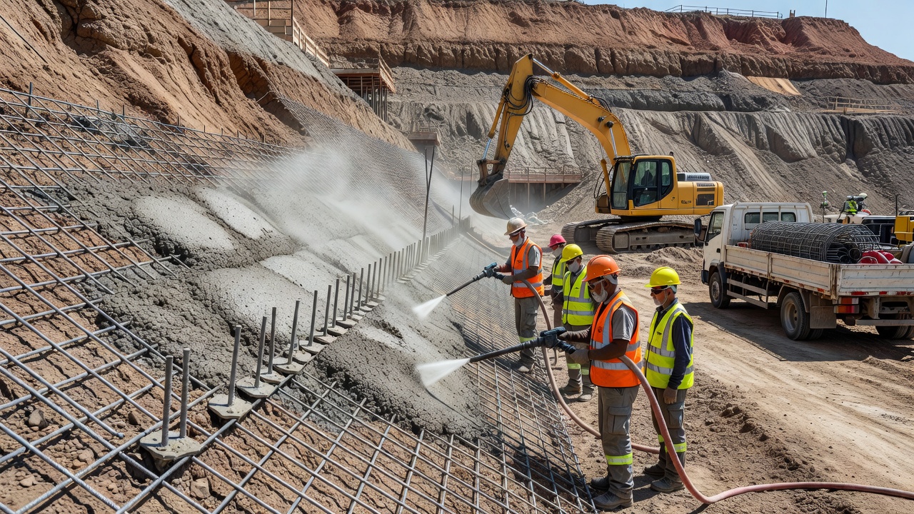
A soil nail wall is an in-situ earth retention system constructed by installing closely spaced, grouted steel bars (nails) into a soil slope or excavation face as excavation proceeds from the top downward. The nails act as passive reinforcements that mobilize tensile forces as the soil mass deforms slightly during excavation, creating a coherent reinforced soil structure capable of resisting lateral earth pressures. The exposed face is typically covered with shotcrete — a pneumatically applied concrete — to provide surface stability, distribute loads among nails, and protect against weathering.
The fundamental mechanism of soil nailing is distinct from other earth retention systems. Each nail develops pullout resistance through the bond between the cementitious grout and the surrounding soil along the nail length behind the potential failure surface. As the excavation face advances and the soil mass undergoes minor deformation, tensile forces are mobilized in the nails. This creates a stable reinforced zone that behaves as a gravity retaining structure. The nails resist the driving forces through tension, the grout annulus transfers load to the ground through skin friction, and the facing distributes loads across the nail field.
Soil nail walls are used extensively in highway and airfield applications for: permanent and temporary excavation support, slope stabilization, road widening beneath existing bridge abutments, tunnel portal stabilization, repair and reconstruction of existing retaining structures, hybrid walls combining soil nails with other retention methods, and shored mechanically stabilized earth (SMSE) walls. The FHWA Geotechnical Engineering Circular No. 7 (GEC 007), Publication No. FHWA-NHI-14-007, serves as the definitive reference manual for soil nail wall design, construction, and inspection in the United States.
A soil nail wall system comprises several integrated components that work together to create a stable earth retention structure. Each component serves a specific function and must be designed and constructed to specified standards per FHWA GEC 007 and AASHTO LRFD Bridge Design Specifications.
The nail bar — also referred to as the tendon — is the primary tensile reinforcement element. It is typically a solid steel bar conforming to ASTM A615 Grade 60 or Grade 75, or ASTM A706 Grade 60 for weldable applications. Bar diameters commonly range from No. 6 (19 mm / 0.75 in.) to No. 11 (36 mm / 1.41 in.) , with No. 8 (25 mm / 1.0 in.) and No. 10 (32 mm / 1.27 in.) being the most prevalent in U.S. practice. The bar is typically fabricated with a threaded or upset end to accommodate the bearing plate and nut assembly at the wall face.
Hollow bar soil nails (HBSNs) are an alternative to solid bars. These are continuous-thread hollow bars that serve as both the drill rod and the reinforcement element. The hollow bar is advanced into the ground with a sacrificial drill bit while grout is pumped through the bar simultaneously, eliminating the need for a pre-drilled hole. HBSNs are particularly advantageous in collapsing soils or where groundwater inflow prevents open-hole drilling. FHWA GEC 007 dedicates an entire chapter (Chapter 10) to HBSN design and construction considerations.
The grout column surrounding the nail bar serves two critical functions: (1) transferring load from the bar to the surrounding soil through interface bond stress, and (2) providing a corrosion protection barrier around the steel. The grout is typically a neat cement grout with a water-cement ratio of 0.40 to 0.50 , often containing a water-reducing admixture or a small percentage of sand (typically not exceeding 30 percent by weight of cement) for improved volume stability.
Grout compressive strength requirements per FHWA GEC 007:
| Parameter | Requirement | Test Standard |
|---|---|---|
| Minimum 28-day compressive strength | 24 MPa (3,500 psi) | ASTM C109 or C39 |
| Minimum grout cover over bar for corrosion | 19 mm (0.75 in.) for temporary, 25 mm (1.0 in.) for permanent | N/A |
| Water-cement ratio | 0.40 to 0.50 (unless otherwise specified) | N/A |
| Slump | 150 to 200 mm (6 to 8 in.) for tremie placement | N/A |
| Maximum aggregate size | None in neat grout; 10 mm (3/8 in.) in sanded grout | N/A |
The grout is placed by tremie method — a grout tube is inserted to the bottom of the drill hole and withdrawn as grout is pumped, ensuring complete filling from the bottom up with no air voids. A mud balance is used in the field to verify grout density meets specified requirements, typically corresponding to a specific gravity of 1.8 to 2.0.
Centralizers are devices attached along the nail bar to maintain a uniform grout cover thickness around the bar by centering it within the drill hole. Per FHWA GEC 007, centralizers should be placed at maximum 2.5 m (8 ft) spacing along the bar and positioned to ensure the bar is concentric in the hole. Centralizers must be of adequate diameter — typically 25 to 50 mm (1 to 2 in.) less than the drill hole diameter — and fabricated from materials compatible with the corrosion protection system (e.g., PVC, plastic, or galvanized steel).
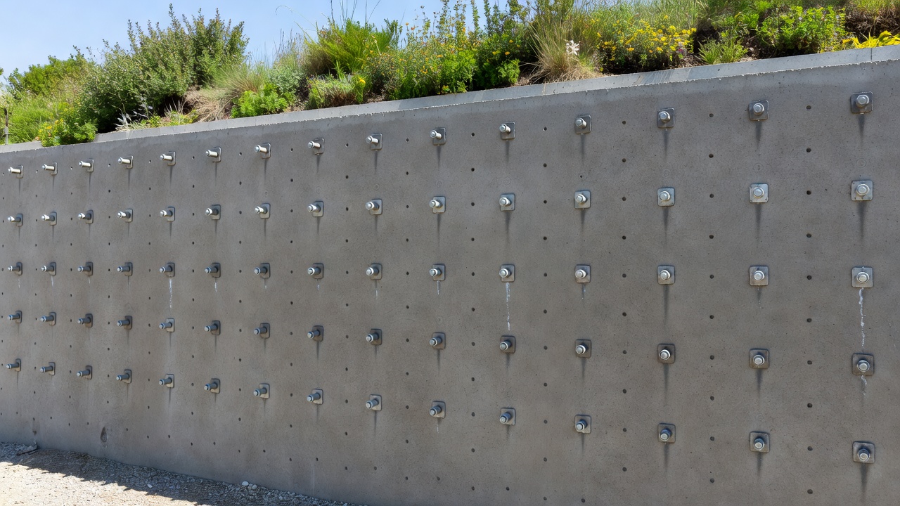
The facing is the exposed structural element that distributes nail head loads to the soil mass and provides surface stability against raveling and weathering. Facing types are discussed in detail in a dedicated section below.
The drainage system is a critical component often underestimated in importance. Hydrostatic pressure behind the facing can significantly reduce wall stability and service life. Drainage typically consists of a geocomposite strip drain (drain board) placed vertically behind the shotcrete facing at strategic locations, connected to horizontal PVC weepholes that pass through the facing at regular intervals. Per FHWA GEC 007, weepholes should be 75 to 100 mm (3 to 4 in.) in diameter and spaced 1.5 to 3.0 m (5 to 10 ft) horizontally and vertically , with the lowermost row placed near the base of the wall.
The defining feature of soil nail wall construction is the top-down sequence — excavation, nailing, and facing are performed in lifts from the top of the wall to the base. This is fundamentally different from bottom-up construction methods like cast-in-place concrete walls or MSE walls, where the wall is built from the base upward.
Step 1 — Initial Excavation Lift: The first excavation lift exposes the soil face to a depth equal to the planned nail vertical spacing, typically 1.0 to 1.5 m (3.3 to 5 ft) . The excavation must be performed with care to maintain a stable unsupported face. The stand-up time of the soil governs the maximum allowable excavation height per lift.
Step 2 — Drilling: Drill holes are advanced into the excavated face at the planned inclination (typically 10 to 20 degrees below horizontal ) to ensure positive grout placement. Drill hole diameters typically range from 100 to 200 mm (4 to 8 in.) depending on the bar diameter, corrosion protection system, and required grout cover. Drilling methods include rotary drilling with casing in caving soils, rotary-percussive drilling in stiff soils and rock, or auger drilling in cohesive soils.
Step 3 — Nail Installation and Grouting: The nail bar with attached centralizers is inserted into the drill hole. A grout tube is inserted to the hole bottom, and grout is pumped via the tremie method until clean grout returns at the hole collar. For HBSNs, grouting is simultaneous with drilling as the hollow bar advances.
Step 4 — Initial Facing Construction: After all nails in a lift are installed and grouted, the initial facing is constructed. This typically involves placing welded wire fabric (WWF) or steel reinforcing mesh, attaching bearing plates and nuts to the nail bars, then applying shotcrete to a typical thickness of 100 to 150 mm (4 to 6 in.) . The initial facing provides temporary support until the next excavation lift.
Step 5 — Drainage Placement: Geocomposite strip drains are placed vertically against the soil face before shotcrete application, aligning with planned weephole locations. PVC pipes or formers are installed through the facing to create weephole openings.
Step 6 — Repeat for Subsequent Lifts: Steps 1 through 5 are repeated for each excavation lift until the full wall height is reached. Nails in the upper lifts are already curing and developing bond strength while lower lifts are being installed.
Step 7 — Final Facing Construction (if specified): After the full wall height is excavated and nailed, a permanent final facing may be constructed. This can be an additional layer of reinforced shotcrete, cast-in-place reinforced concrete, or precast concrete panels. The final facing provides long-term durability, aesthetic finish, and additional structural capacity.
The excavation lift height is constrained by the soil’s stand-up time — the duration the unsupported face remains stable without sloughing or raveling. In favorable soils (stiff clays, dense sands with cohesion), stand-up times of 24 to 48 hours are achievable, allowing single-lift construction. In marginal soils, shorter lift heights and rapid shotcrete application may be required.
Nail installation rate is a key productivity factor. A typical track-mounted drill rig can install 30 to 60 nails per day depending on ground conditions, nail length, drilling method, and site access. Production rates directly influence project scheduling costs.
The facing is a structural element that distributes nail head reaction forces to the soil mass, provides surface confinement to prevent raveling, and serves as a protective layer against weathering. FHWA GEC 007 identifies three primary facing types for permanent soil nail walls.
Shotcrete facing is the most common facing type in U.S. practice, accounting for the majority of permanent soil nail walls. Shotcrete is pneumatically applied concrete that achieves high strength, low permeability, and excellent bonding to the soil face. Key specifications per FHWA GEC 007:
| Parameter | Requirement |
|---|---|
| Minimum 28-day compressive strength | 28 MPa (4,000 psi) |
| Minimum thickness (initial + final) | 150 mm (6 in.) for permanent walls |
| Maximum aggregate size | 10 mm (3/8 in.) |
| Reinforcement | WWF (typically 6x6 - W2.9/W2.9) plus headed studs or rebar at nail heads |
| Application method | Dry-mix or wet-mix shotcrete per ACI 506 |
Shotcrete facing is applied in two stages: an initial facing (100 to 150 mm thick) placed immediately after nail installation to stabilize the excavation lift, and a final facing (additional 100 to 150 mm) placed after the full wall height is completed. The final facing incorporates structural reinforcement — typically headed shear studs welded to the bearing plate or hooked rebar — to transfer nail forces to the facing.
Cast-in-place (CIP) reinforced concrete facing is used where higher structural capacity, architectural finish, or additional durability is required. CIP facing is typically constructed after the full wall height is excavated and all nails are installed and tested. Formwork is erected against the shotcrete initial facing, reinforcing steel is placed, and concrete is cast in lifts.
CIP facings typically range from 200 to 350 mm (8 to 14 in.) in thickness with Grade 60 reinforcing steel in both horizontal and vertical directions. The nail head connection to CIP facing typically involves a headed stud assembly cast into the concrete, with the bearing plate embedded behind the reinforcing cage.
Precast concrete panel facing is a less common but viable option, primarily used where architectural appearance, accelerated construction, or uniform finish quality are priorities. Precast panels are typically 75 to 125 mm (3 to 5 in.) thick with steel reinforcement and are cast off-site to controlled quality standards. The panels are erected against the shotcrete initial facing and connected to the nail heads through embedded connection hardware.
Precast panel facing requires precise fabrication tolerances and careful coordination of nail head locations with panel connection points. The connection system must accommodate minor variations in nail location and inclination while providing full structural load transfer.
Corrosion protection for soil nails is a critical durability consideration. Soil nails are permanent steel elements installed in a potentially corrosive environment — the soil. Moisture, oxygen, chlorides, sulfates, and varying soil pH can promote steel corrosion, leading to cross-section loss and eventual structural failure. FHWA GEC 007 classifies corrosion protection into two classes based on the severity of the soil environment and the required design life.
Before selecting a corrosion protection system, the soil environment must be characterized through laboratory testing per ASTM G57 and related standards. The following parameters define soil corrosivity:
| Parameter | Non-Corrosive | Moderate | Corrosive | Test Standard |
|---|---|---|---|---|
| Electrical resistivity | > 5,000 ohm-cm | 2,000 - 5,000 ohm-cm | < 2,000 ohm-cm | ASTM G57 (Wenner 4-pin) |
| pH | 5.5 - 10 | 4.5 - 5.5 or 10 - 12 | < 4.5 or > 12 | ASTM D4972 |
| Chlorides (Cl⁻) | < 100 ppm | 100 - 500 ppm | > 500 ppm | AASHTO T291 |
| Sulfates (SO₄²⁻) | < 200 ppm | 200 - 2,000 ppm | > 2,000 ppm | AASHTO T290 |
| Redox potential | > -200 mV | N/A | < -200 mV | ASTM G200 |
Class I protection is required when soil conditions are aggressive (low resistivity, low pH, high chlorides or sulfates) or when the consequences of corrosion failure are high (critical infrastructure, inaccessible locations). Class I systems include:
Class I systems require the entire nail — including the bar, centralizers, bearing plate, and nut — to be corrosion-protected. Field handling requires careful inspection for coating damage, with damaged areas repaired per manufacturer specifications before installation.
Class II protection is used for non-aggressive soil environments with adequate grout cover and subsurface drainage. The primary protection mechanism is the cementitious grout cover surrounding the steel bar. Per FHWA GEC 007:
In Class II systems, the bearing plate and nut are typically hot-dip galvanized. The exposed nail head and connection may receive additional protection such as bituminous coating or grease-filled caps.
An alternative corrosion protection approach recognized by FHWA is sacrificial steel thickness — designing the nail bar with an additional cross-sectional area that can be lost to corrosion over the design life without compromising structural capacity. This approach is typically used only for temporary nails or where grout cover provides the primary barrier and the corrosion rate is well-characterized.
The loss rate used for design is typically 0.012 to 0.025 mm/year (0.5 to 1.0 mil/year) per FHWA guidance, depending on soil conditions. For a 75-year design life, the sacrificial thickness would range from 0.9 to 1.9 mm (36 to 75 mils) added to the required structural bar radius.
Regular inspection of soil nail walls is essential for infrastructure asset management. The FHWA Geotechnical Engineering Circular No. 7 and FHWA-CFLHD retaining wall inspection protocols establish systematic inspection procedures for soil nail walls.
Crack inspection involves identifying crack type, width, pattern, and density on the shotcrete or concrete facing:
Crack mapping should be performed using a crack comparator gauge or digital caliper, with crack locations plotted on an elevation view of the wall. Crack widths exceeding 1.5 mm (0.06 in.) or showing evidence of ongoing movement require engineering evaluation per FHWA guidelines.
Deformation monitoring identifies global instability or localized distress:
Per FHWA GEC 007, total wall movements are typically less than 0.3% to 0.5% of the wall height for walls constructed in favorable soils. Movements exceeding 25 mm (1 in.) or accelerating rates require investigation.
Drainage failure is one of the most common causes of soil nail wall distress. Inspection items include:
The nail head assembly — bearing plate, nut, and connection hardware — must be visually inspected for:
Corrosion assessment includes both visual indicators and quantitative measurements:
Monitoring programs for soil nail walls serve multiple purposes: verifying design assumptions during construction, documenting as-built performance, and detecting ongoing deterioration for long-term asset management.
During construction, monitoring includes verification nail testing, proof testing, and grout sampling. Verification nails are sacrificial nails installed before production work to verify the assumed grout-to-ground bond values. Per FHWA GEC 007: two or more verification nails are required per wall, tested to 200% of the design tensile load (DTL) . Proof testing is performed on 5% of production nails (minimum one per wall) tested to 150% of DTL.
After construction, permanent soil nail walls should be monitored at regular intervals:
| Monitoring Method | Measurement | Frequency | Threshold for Action |
|---|---|---|---|
| Survey targets | Horizontal and vertical displacement | Annually | > 25 mm cumulative or > 5 mm/year |
| Inclinometer | Subsurface lateral deformation | Annually (first 3 years), then every 2-3 years | > 15 mm cumulative or accelerating |
| Visual inspection | Facing cracks, drainage, corrosion | Annually | Per facing crack criteria above |
| Piezometer | Groundwater level behind wall | Semi-annually | Rising trends or seasonal high exceeding design |
| Load cells | Nail head load (on selected nails) | Annually | > 110% of DTL |
Per FHWA GEC 007, the following acceptance criteria apply to soil nail wall performance:
Understanding the differences between soil nail walls, tieback (anchored) walls, and mechanically stabilized earth (MSE) walls is essential for selecting the appropriate earth retention system.
| Parameter | Soil Nail Wall | Tieback (Anchored) Wall | MSE Wall |
|---|---|---|---|
| Construction sequence | Top-down | Typically bottom-up | Bottom-up |
| Reinforcement mechanism | Passive — mobilized by soil deformation | Active — post-tensioned against structural waler/wall | Passive — tensile reinforcement in select granular backfill |
| Reinforcement type | Grouted steel bars (nails) | High-strength steel strands or bars (anchors) | Steel strips, geostraps, or geogrid sheets |
| Typical length | 0.5 to 1.0 times wall height | 1.0 to 2.0 times wall height | 0.7 to 1.0 times wall height |
| Typical spacing | 1.0 to 2.0 m (3 to 6 ft) each way | 1.5 to 3.0 m (5 to 10 ft) each way | 0.5 to 1.0 m (1.5 to 3 ft) reinforcement layers |
| Load application | Nails stressed by soil movement after construction | Anchors pre-tensioned to 70-80% of design load | Reinforcement stressed during backfill compaction |
| Facing type | Shotcrete, CIP concrete, precast panels | Reinforced concrete (waler beams) or soldier piles | Precast concrete panels, modular blocks, or wire mesh |
| Typical wall height | 3 to 15 m (10 to 50 ft) | 6 to 30 m (20 to 100 ft) | 3 to 30 m (10 to 100 ft) |
| Relative cost | $20 - $45 per sq ft of wall face | $35 - $75 per sq ft | $15 - $35 per sq ft |
| Suitable soils | Stiff clays, dense sands, weathered rock | Most soils with competent bond zone behind failure surface | SELECT granular backfill required (typically imported) |
| Water table | Must be below excavation base or controlled by dewatering | Anchors require bonded zone in suitable stratum below water table | Must be below base of wall or controlled by underdrains |
| Right-of-way requirement | Minimal — nails are within slope face | Moderate — anchor bond zone must be outside retained soil mass | Significant — excavation for backfill compaction |
Soil nail walls are preferred when: right-of-way is restricted, access for backfill compaction is limited, the excavation face has adequate stand-up time, the soil provides sufficient bond capacity, and the wall height is moderate (3 to 15 m). They are particularly advantageous for widening projects beneath existing bridge abutments and tunnel portal stabilization.
Tieback walls are preferred when: the excavation is deep (> 15 m), high lateral loads must be resisted, active pre-stressing is needed to limit wall movement, and a suitable bond zone exists behind the potential failure surface. Tiebacks are common in deep urban excavations and temporary shoring.
MSE walls are preferred when: right-of-way is available for backfill compaction, a suitable granular backfill source is available, the foundation can support the gravity wall loads, and high aesthetic standards require architectural facing. MSE walls are the most common retaining wall type for highway approaches and bridge abutments.
Soil nail walls are used at airports for slope stabilization, excavation support, and retaining structures in areas where conventional retaining walls are impractical due to access constraints, right-of-way limitations, or operational requirements.
Per ICAO Annex 14, Volume I — Aerodrome Design and Operations, retaining structures within the runway strip or runway end safety area (RESA) must not create a hazard to aircraft. FAA Advisory Circular AC 150/5300-13C — Airport Design requires that retaining walls in runway and taxiway areas be frangible or protected by adequate separation distance. Soil nail walls — with their low-profile shotcrete facing — are often preferred in airfield environments because they can be constructed with minimal above-ground protrusion and can be integrated into the natural slope.
Slope stabilization near runway ends: Runway end safety areas (RESAs) and runway strips often require grading and stabilization of adjacent slopes. Soil nail walls are used to stabilize cut slopes created during RESA grading, providing permanent retention without encroaching on the safety area. At Yeager Airport (CRW) in Charleston, West Virginia, a major slope stabilization project using soil nail technology was implemented adjacent to the runway to address slope instability threatening airport operations.
Roadway and taxiway widening: Where taxiways or service roads are widened into existing slopes, soil nail walls provide efficient excavation support with minimal impact on adjacent operations. The top-down construction sequence allows the wall to be built directly against the existing slope face.
Tunnel portal stabilization: At airports with underground transportation systems or pedestrian tunnels, soil nail walls are used to stabilize tunnel portal excavations. The soil nail wall can be constructed before tunnel excavation begins, creating a stable headwall for portal entry.
Retaining walls adjacent to runways: Where terrain constraints require retaining walls adjacent to active runways, soil nail walls offer advantages over cast-in-place or MSE walls: the shotcrete facing produces no glare (unpolished concrete), the low-profile facing minimizes FOD (foreign object debris) concerns, and the wall is inherently frangible — the steel nails and shotcrete facing can be damaged without catastrophic failure if struck.
Airport soil nail walls require particularly robust drainage systems. ICAO and FAA standards mandate positive drainage away from pavements. Weephole discharge must be directed to collection systems that prevent water flow across pavement surfaces. The drainage layer behind the facing must be designed to prevent ice lens formation in freeze-thaw climates, as ice buildup can cause spalling of the shotcrete facing and obstruct drainage paths.
The definitive reference for soil nail wall technology in the United States is FHWA Geotechnical Engineering Circular No. 7 (GEC 007) — Soil Nail Walls — Reference Manual, Publication No. FHWA-NHI-14-007, published in February 2015. This 425-page document replaces the earlier FHWA0-IF-03-017 (2003) and represents the current state of practice.
| Chapter | Content |
|---|---|
| Chapter 1 — Introduction | Definition, historical development, design philosophy |
| Chapter 2 — Applications and Feasibility | Applications, advantages/limitations, soil suitability classification, risk management |
| Chapter 3 — Construction Materials and Methods | Components, construction sequence, drilling methods, grouting, facing construction |
| Chapter 4 — Information Required for Design | Subsurface investigation, laboratory testing, soil parameters, bond strength, corrosion potential, frost, seismic data |
| Chapter 5 — Resisting Mechanisms and Limit States | Load transfer, LRFD framework, limit states (overall stability, strength, service, extreme) |
| Chapter 6 — Design of Soil Nail Walls | Step-by-step design procedure, nail configuration, stability analysis, facing design |
| Chapter 7 — Corrosion Protection | Corrosivity assessment, Class I and II protection systems, sacrificial steel design |
| Chapter 8 — Contracting and Specifications | Contracting approaches, technical specifications, payment provisions |
| Chapter 9 — Inspection and Testing | Construction monitoring, verification and proof testing, quality control checklists |
| Chapter 10 — Hollow Bar Soil Nails | HBSN design and construction considerations, pullout test program results |
GEC 007 introduces a dual-platform design framework that integrates both Allowable Stress Design (ASD) with factors of safety and Load and Resistance Factor Design (LRFD) per AASHTO LRFD Bridge Design Specifications (7th Edition). This framework allows practitioners to work in either platform while maintaining consistent safety levels.
Key resistance factors for LRFD design of soil nail walls per GEC 007:
| Limit State | Resistance Factor (φ) |
|---|---|
| Nail pullout (grout-to-ground bond) | 0.50 - 0.70 |
| Nail tensile resistance | 0.75 - 0.90 |
| Facing flexure | 0.90 (per AASHTO) |
| Facing punching shear | 0.80 - 0.90 |
| Overall stability (global) | 0.65 - 0.75 |
| Lateral sliding | 0.80 - 0.90 |
| Basal heave | 0.50 - 0.70 |
GEC 007 classifies soils for soil nailing into three categories:
Favorable soils: Stiff to hard fine-grained soils (clays, silts), dense granular soils with cohesion, glacial tills, cemented soils, weathered rock, soft rock. These soils provide adequate stand-up time (24+ hours), sufficient bond capacity (> 100 kPa / 2,000 psf), and minimal construction difficulties.
Difficult soils: Loose granular soils with < 5% fines below the water table, soft to medium clays (undrained shear strength 25-50 kPa), cohesionless sands above the water table with > 30% relative density, soils with cobbles and boulders. These soils require special construction measures such as shorter lift heights, rapid shotcrete application, casing advancement during drilling, or HBSN installation.
Unfavorable soils: Very soft clays (undrained shear strength < 25 kPa), loose sands below the water table with < 5% fines, organic soils (peat, muck), liquefiable soils (saturated loose sands with (N1)₆₀ < 15), uncompacted fill, soils with high creep potential. These soils are generally unsuitable for soil nailing without extensive ground modification or alternative retention systems.
The manual emphasizes that groundwater control is critical to successful soil nailing. The excavation face should be kept above the groundwater table, or dewatering measures (wellpoints, deep wells, or drainage blankets) must be implemented to prevent seepage erosion, loss of soil strength, and grout washout during construction.
TarmacView provides AI-powered visual inspection solutions for airport retaining structures, slope stabilization systems, and geotechnical assets — from soil nail walls to MSE walls. Our drone-based inspection platform detects facing cracks, drainage failures, corrosion, and deformation with quantitative accuracy.
Retaining walls are engineered earth-retaining structures that hold back soil or rock from buildings, bridge approaches, roadways, and airport facilities, preve...
Epoxy injection is a structural crack repair method where low-viscosity epoxy resin is pressure-injected into concrete cracks to restore structural integrity an...
Cementitious grouting uses fluid cement-based mixtures poured or pumped to fill cracks, voids, or spaces in concrete — including tendon duct grouting, crack inj...