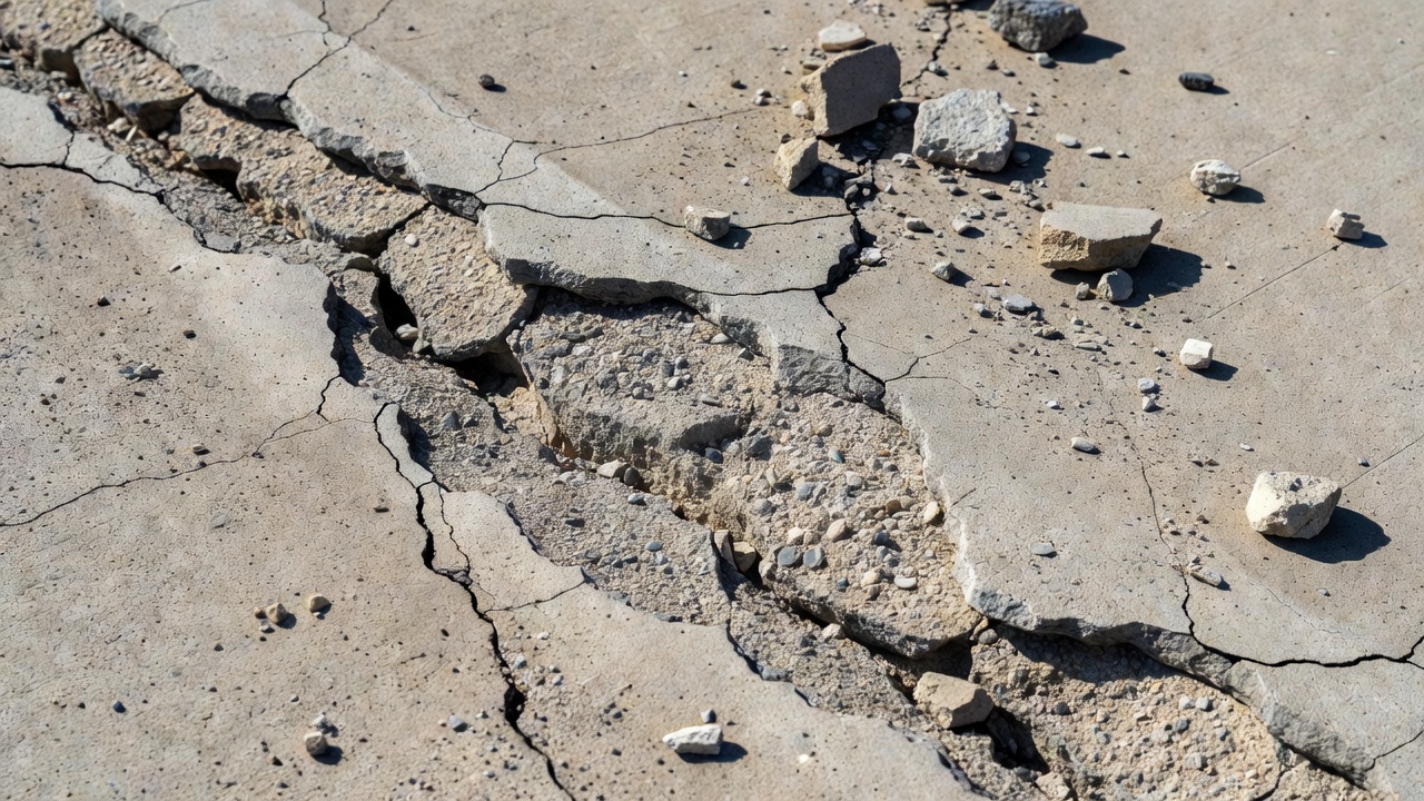
Spalling is the breaking, chipping, or loss of concrete material at pavement joints, edges, or cracks — a critical defect in airport runways, taxiways, bridges, and road surfaces that generates FOD and threatens aircraft safety.
Spalling in Pavement: Complete Technical Guide for Airport and Infrastructure Inspection
What is Spalling?
Spalling is the loss, breaking, chipping, or fraying of concrete material from the surface of a pavement slab — occurring most commonly along the edges of joints, at slab corners, or along the faces of cracks. The resulting breakout produces loose fragments, chunks, or flakes of concrete that separate from the parent slab, leaving behind irregular, angular voids in the pavement surface.
The term is precisely defined in all major pavement inspection standards. The FAA PAVEAIR system (which implements ASTM D5340) defines joint spalling as “the breakdown of the slab edges within 2 ft. (0.6 m) of the side of the joint. A joint spall usually does not extend vertically through the slab but intersects the joint at an angle.” The American Concrete Pavement Association (ACPA) defines spalling as “the breaking, cracking, chipping, or fraying of the slab edges that occurs within 50 mm (2 in.) of joints and cracks or their corners.” The FHWA Long-Term Pavement Performance (LTPP) Distress Identification Manual defines it as “cracking, breaking, chipping, or fraying of slab edge within 0.3 m from the face of the longitudinal or transverse joint.”
A critical geometric distinction separates spalling from other similar defects: a spall’s fracture plane intersects the joint or crack at an angle, not vertically. This differentiates it from a corner break, where the crack extends vertically through the full slab thickness. Spalling is also distinct from scaling, which is the shallow, widespread loss of surface mortar and fine aggregate, not the discrete breakout of material at joints. Understanding these distinctions is essential for accurate distress identification and PCI scoring.
Spalling is a core defect type in concrete pavement inspection — specifically for airport runways, taxiways, aprons, bridge decks, and road surfaces. It is recorded as a distinct distress under ASTM D5340 (the definitive standard for airport Pavement Condition Index surveys), under STANAG 7181 for NATO military airfields, and under the FHWA LTPP Distress Identification Manual for road and highway pavements. In all these frameworks, spalling is treated not merely as a cosmetic imperfection but as a structural and safety-critical defect requiring systematic measurement, severity classification, and timely repair.
Types of Spalling
Spalling in concrete pavements is not a single uniform phenomenon. It manifests in several distinct forms, each with its own location, geometry, cause, and repair implications.
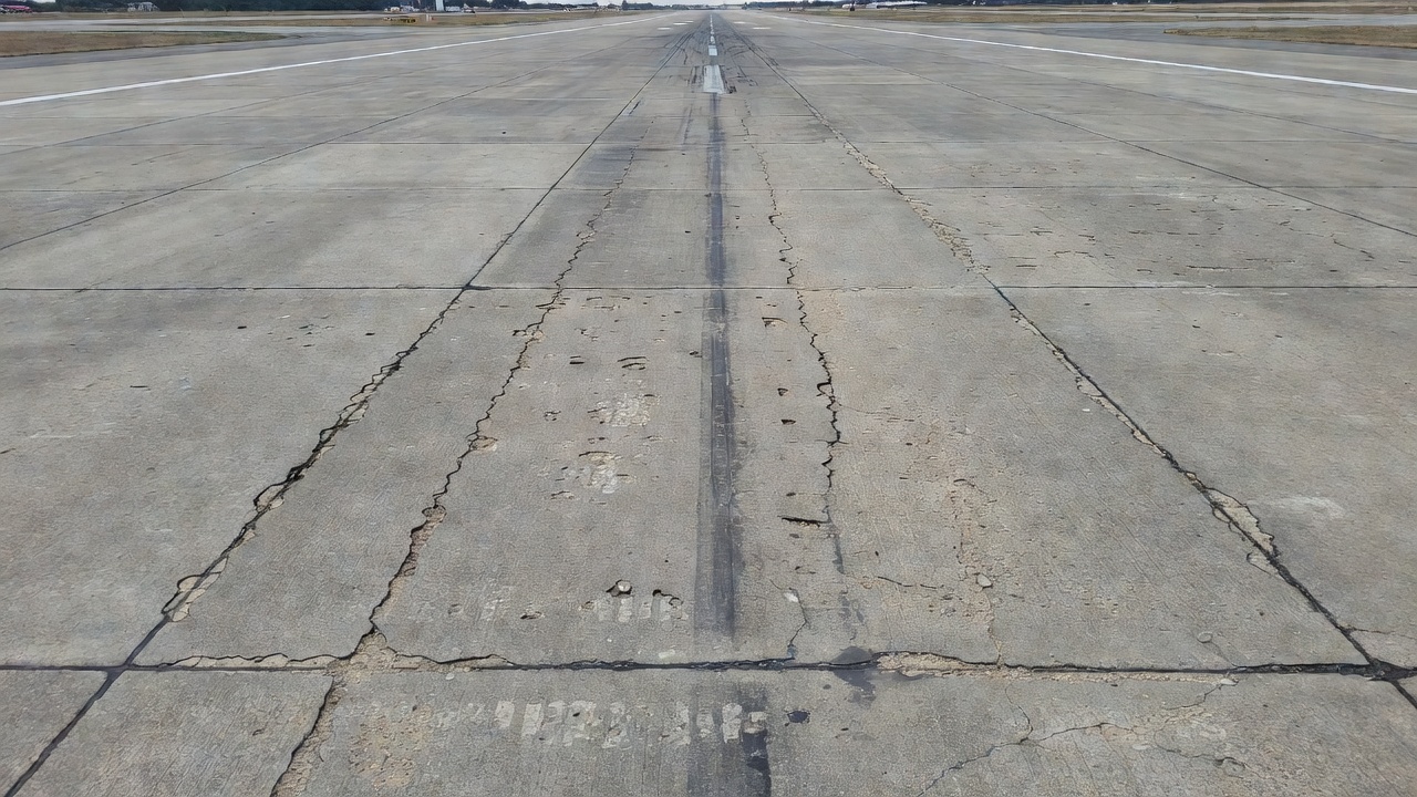
Joint Spalling (Transverse and Longitudinal) is the most common type encountered on airport and highway concrete pavements. It occurs along transverse or longitudinal joints, within 2 ft (600 mm) of the joint face for airfield surveys (PAVER/ASTM D5340) or within 300 mm for highway surveys (FHWA LTPP). The fracture plane intersects the joint at an angle rather than vertically. In the PAVER distress coding system, transverse joint spalling carries Distress Code 74 and longitudinal joint spalling is covered under the same category. The FHWA LTPP system records these separately as Type 6 (Spalling of Longitudinal Joints) and Type 7 (Spalling of Transverse Joints), both measured in meters of affected joint length. Joint spalling may range from minor fraying of the joint edge — where material is still largely in place — to complete breakout of substantial chunks of concrete, exposing the joint interior and leaving sharp, irregular edges.
Corner Spalling occurs at the corner of a slab where a transverse and a longitudinal joint meet. PAVER Distress Code 75 covers this type. The key diagnostic distinction is geometry: a corner spall’s fracture intersects both joints at an angle, whereas a corner break (Code 62) is a crack that extends vertically through the full slab thickness. If the crack intersects both joints more than 2 ft (600 mm) from the corner, it is classified as a corner break; if less than 2 ft, it is likely a corner spall. Corner spalling is particularly associated with inadequate subgrade support, dowel bar corrosion or lockup, and concentrated stress from thermal slab movement.
Surface Spalling (Mid-Slab Spalling) occurs on the slab surface away from joints or cracks. It is caused by poor quality materials, freeze-thaw action, or overworking the concrete during finishing — which draws water and fines to the surface, increasing the local water-cement ratio and reducing surface strength. Surface spalling is distinct from scaling (which is shallower and more widespread) and typically involves deeper material loss.
Crack Spalling develops along cracks within the slab body, not at constructed joints. As cracks deteriorate, parallel micro-fracturing along their edges can produce spalling. The FHWA LTPP system uses spalling width as one of the key criteria for assigning severity levels to longitudinal and transverse cracks: spalling less than 75 mm wide indicates moderate severity, while spalling 75 mm or wider indicates high severity.
D-Cracking Related Spalling is a special case associated with durability (D) cracking — the progressive disintegration of concrete caused by freeze-thaw cycling of susceptible aggregates. D-cracking begins at the bottom of the slab and moves upward, producing crescent-shaped hairline cracking near joints. When D-cracking reaches the surface, extensive spalling may result. Under PAVER protocol, if corner or joint spalling is caused by D-cracking, only D-cracking is recorded — not spalling separately — because D-cracking overrides other distress recording when present at high severity.
Causes of Spalling
Understanding the root causes of spalling is essential for selecting the correct repair strategy and implementing effective preventive maintenance. Spalling results from a combination of mechanical, environmental, and material-related factors.
Infiltration of Incompressible Materials into Joints is the primary and most prevalent cause of joint spalling on airport and highway pavements. When joint sealant fails or is absent, sand, grit, small stones, and concrete fragments infiltrate open joints during cool weather when slabs are contracted. When temperatures rise and slabs expand, these incompressible materials prevent normal joint closure and generate extreme compressive stress at the joint face. The concrete, unable to withstand the point-bearing pressure, crushes and spalls. This same mechanism, when severe, leads to blowups — the upward buckling of slabs at joints — the most extreme form of joint failure. The FAA AC 150/5380-6C explicitly notes that “accumulation of incompressible materials in joints leads to spalling of the concrete, which is a source of FOD.”
Traffic and Aircraft Loading contributes significantly to joint spalling, particularly at locations where load transfer between slabs is compromised. Repeated heavy loading at joints with poor load transfer creates excessive compressive and flexural stresses at the slab edge. Modern wide-body commercial aircraft — such as the Boeing 747 or Airbus A380 — operate with tire pressures exceeding 200 psi (approximately 1.4 MPa), which amplifies near-surface stress concentrations at joint edges. High-speed ground operations further increase the dynamic loading component.
Dowel Bar Corrosion and Lockup is a structural cause of corner and joint spalling. Steel dowel bars placed across transverse joints to transfer loads between slabs can corrode, especially in environments where de-icing chemicals are applied. Corrosion causes the steel to expand, generating forces on the surrounding concrete that crack and spall the joint face. Epoxy-coated and stainless steel dowels were developed specifically to address this problem. Locked-up dowels — bars that have seized due to corrosion or improper installation and no longer allow joint movement — generate high internal stresses that produce spalling as the slab attempts to expand and contract with temperature.
Poor Construction Practices are a significant source of early-age spalling. Overworking the concrete surface during finishing draws water and fine particles to the surface, increasing the local water-cement ratio and producing a weak surface layer prone to spalling. Placing joint-forming inserts (plastic or metal) too close to the surface can create stress concentration points. Late sawing of contraction joints — sawing too long after the concrete pour — can induce micro-fracturing at the joint face that later develops into spalling. Insufficient curing, substandard aggregates, and improper mix design all reduce the concrete’s resistance to spalling.
Freeze-Thaw Cycling attacks concrete that is not adequately air-entrained. Water infiltrating joints or cracks freezes, expands by approximately 9% in volume, and fractures the concrete at the joint edge. Repeated freeze-thaw cycles progressively deteriorate the joint face. This is a major cause of joint spalling in cold climates and is closely related to D-cracking when susceptible aggregates are involved.
Alkali-Silica Reactivity (ASR) is a chemical reaction between alkali compounds in cement paste and reactive silica in certain aggregates. The reaction produces an expansive silica gel that absorbs moisture and swells, generating internal pressure that causes map cracking and, ultimately, spalling. ASR is a long-term durability problem that can affect pavements 10–20 years after construction.
Joint Maintenance Failure is both a cause and an accelerating factor. Failure to maintain joint sealant allows water infiltration (weakening the subgrade, leading to pumping and loss of slab support), incompressible material infiltration, and freeze-thaw damage to unsupported joint edges. ICAO Doc 9137 Part 9 emphasizes that preventive maintenance — particularly joint sealing — is of the highest importance for airport pavement longevity.
Inspection and Identification
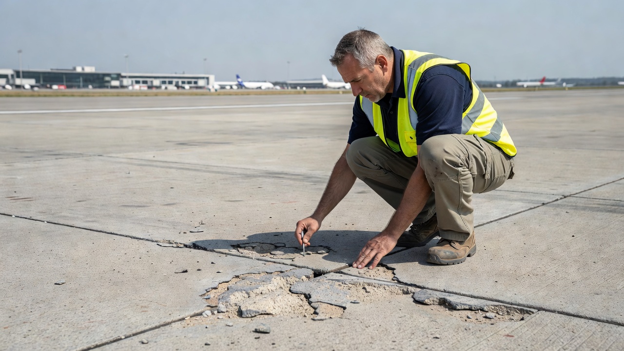
Spalling is identified primarily through visual inspection, supplemented by standardized quantitative assessment tools. The inspection protocols for airport pavements are defined by both ICAO and FAA, with different levels of frequency and detail.
Visual Inspection Indicators that inspectors look for include: missing or loose concrete fragments at joint edges or crack edges; irregular, broken surfaces along joints; exposed aggregate or reinforcement (rebar); angular fracture surfaces distinguishing spalls from vertical cracks; dark staining or discoloration (indicating possible D-cracking); and debris on the pavement surface adjacent to joints. The presence of loose fragments that can be dislodged by hand is a reliable indicator of medium-to-high severity spalling.
ICAO Inspection Frequency Requirements (per ICAO Doc 9137 Part 9 and SACAA Technical Guidance Material for Aerodrome Civil Infrastructure Maintenance) establish a tiered system:
Inspection Type
Frequency
Method
Daily operational
Minimum 3 per day on movement area
Vehicle, appropriate speed
Weekly detailed
At least once per week for all aerodrome pavements
Preferably on foot; slow vehicle acceptable
Annual engineering
At least once per year for all movement area pavements
On foot; by professionally qualified engineer
Special
After unusual events, construction completion, complaints
As required
Daily inspections are conducted from a moving vehicle at a speed appropriate to detect FOD and obvious surface defects. Weekly inspections give particular attention to high-load areas — departure taxiways, apron parking stands, take-off taxiways, runway intersections, and touchdown areas. Annual inspections, conducted by a professionally qualified engineer on foot covering the entire movement area, are the primary tool for detecting and documenting spalling and other structural pavement defects. The FAA (AC 150/5380-6C) recommends annual Pavement Condition Index (PCI) assessments for critical surfaces including primary runways and high-traffic taxiways.
Pavement Condition Index (PCI) — ASTM D5340 is the primary quantitative tool for spalling assessment on airport pavements. The PCI is a numerical index from 0 (failed) to 100 (perfect), calculated by surveying sample units of the pavement, recording each distress type and severity, converting distress densities to Deduct Values (DVs) using standard curves, and applying the Corrected Deduct Value (CDV) procedure to arrive at a final PCI score. The methodology is standardized under ASTM D5340 (current edition D5340-23) and implemented through the PAVER™ system developed by the U.S. Army Corps of Engineers (ERDC-CERL). For NATO/military airfields, the equivalent standard is STANAG 7181 ED 1 RD 1.
PCI Range
Condition Rating
86–100
Excellent
71–85
Very Good
56–70
Good
41–55
Fair
26–40
Poor
11–25
Very Poor
0–10
Failed
In PCI surveys, joint spalling and corner spalling are measured by the number of slabs affected at each severity level. The spall zone boundary — the area within which deterioration at a joint is classified as spalling — is defined as within 2 ft (600 mm) of the joint face under ASTM D5340/PAVER for airfields. For road/highway surveys under the FHWA LTPP system, the boundary is 300 mm (0.3 m). Spalling at joints that is small enough to be filled during routine joint seal repair is not recorded as a separate distress in PAVER surveys.
FHWA LTPP Measurement Conventions apply to road and highway concrete pavements. Joint spalling is measured in meters of affected joint length, with a minimum recordable length of 0.1 m (100 mm). Spall width is measured perpendicular to the joint face. Low severity: less than 75 mm wide with material loss. Moderate severity: 75–150 mm wide with material loss. High severity: more than 150 mm wide, or broken into two or more pieces, or containing patch material.
Coring is used when the depth and cause of spalling are not evident from surface inspection alone. A core sample allows direct examination of the fracture plane, presence of D-cracking, condition of dowel bars, and depth of deterioration — all critical inputs for selecting the appropriate repair method.
Severity Classification
The severity of spalling determines the urgency of repair and the repair method selected. Two major classification systems are used: the PAVER/ASTM D5340 system for airfields and the FHWA LTPP system for roads.
Spall is broken into one or two pieces defined by low-severity cracks; little or no FOD potential. OR defined by one medium-severity crack with little or no FOD potential.
Little or none
Medium (M)
Broken into two or more pieces by medium-severity cracks; a few small fragments may be absent or loose. OR defined by one severe, fragmented crack. OR loose material causing some FOD potential.
Some
High (H)
Broken into two or more pieces by high-severity fragmented cracks with loose or absent fragments. OR pieces displaced to the extent that a tire damage hazard exists. OR loose material causing high FOD potential.
High / Tire damage hazard
Corner Spalling Severity — PAVER / ASTM D5340:
Severity Level
Description
Low (L)
Crack has no spalling or minor spalling; no FOD potential. Non-filled crack mean width < 3 mm (1/8 inch). Area between corner break and joints not cracked.
Medium (M)
Crack moderately spalled with some FOD potential. OR non-filled crack width 3–25 mm (1/8–1 inch). OR filler in unsatisfactory condition. OR area between corner break and joints lightly cracked.
High (H)
Crack severely spalled with definite FOD potential. OR non-filled crack width > 25 mm (1 inch) creating tire damage potential. OR area between corner break and joints severely cracked.
An important faulting upgrade rule applies to corner spalling under PAVER: if the corner break is faulted 3 mm (1/8 inch) or more, increase severity to the next higher level. If faulted more than 13 mm (1/2 inch), rate at high severity regardless of crack condition.
Spalling of Longitudinal and Transverse Joints — FHWA LTPP:
Severity Level
Width to Joint Face
Condition
Low
< 75 mm
With loss of material; OR no loss of material and no patching
Moderate
75–150 mm
With loss of material
High
> 150 mm
With loss of material; OR broken into 2+ pieces; OR contains patch material
For crack spalling as a severity indicator in the FHWA system: for both longitudinal and transverse cracks, spalling less than 75 mm wide indicates moderate severity, while spalling 75 mm or wider indicates high severity.
The FAA PASER rating scale (from AC 150/5320-17A, Appendix B), used for simplified visual assessment at general aviation airports, also reflects spalling condition:
PASER Rating
Condition
Spalling Description
5 (Excellent)
No significant defects
No spalling
4 (Good)
Minor surface defects
Joints in good condition; no spalling
3 (Fair)
Moderate distress
Early joint deterioration; slight spalling possible
2 (Poor)
Significant distress
Joints show moderate-to-severe spalling; FOD potential
1 (Failed)
Extensive distress
Severe spalling; dangerous debris; immediate action required
ICAO Standards and Regulatory Framework
ICAO establishes the international framework for aerodrome pavement maintenance and inspection, within which spalling management is embedded.
ICAO Doc 9137 — Airport Services Manual is the primary ICAO technical reference for airport maintenance. Part 9 (Airport Maintenance Practices), First Edition 1984, covers pavement maintenance in Chapter 4, including repair of Portland cement concrete pavements, joint maintenance, crack repair, edge damage repair, and corner repair. The manual classifies maintenance activities into inspection, servicing/overhaul, and repair, and emphasizes that preventive maintenance is of the highest importance for extending pavement service life and maintaining safety. Chapter 4.3 specifically addresses repair of pavement edge damage — directly applicable to spalling at slab edges and corners. Part 2 (Pavement Surface Conditions) covers friction measurement and surface condition assessment, relevant when spalling creates surface irregularities affecting friction characteristics.
ICAO Annex 14 — Aerodromes, Volume 1 (Aerodrome Design and Operations) is the primary international standard for aerodrome certification and operation. While it does not define spalling as a specific term, it establishes the overarching requirements that make spalling management mandatory for all certified aerodromes:
The Annex requires that movement area surfaces — runways, taxiways, and aprons — be maintained in a condition suitable for aircraft operations and free from loose stones, debris, and other objects that could cause damage to aircraft or engines. It mandates that the aerodrome operator ensure the movement area is kept free of foreign object debris (FOD). It requires adequate runway friction characteristics, which can be compromised when spalling creates surface irregularities or drainage impediments. It mandates regular aerodrome inspections to detect and address developing defects. For in-pavement lighting, Annex 14 requires that light fittings maintain structural integrity — spalling around embedded light bases is a specific concern addressed in maintenance guidance.
ICAO Doc 9157 — Aerodrome Design Manual, Part 3 (Pavements) is the design standard for aerodrome pavements, establishing the structural and material requirements that, when met, minimize the risk of premature spalling.
PCN/PCR System: ICAO endorses the Pavement Classification Number (PCN) and, more recently, the Pavement Condition Rating (PCR) system for pavement strength reporting. Significant spalling and joint deterioration reduce the structural integrity of the pavement and directly affect PCN/PCR ratings. Severe spalling may necessitate downgrading of the PCN/PCR, restricting the types of aircraft permitted to use the runway. In extreme cases, complete prohibition of flight operations may result until repairs are completed.
FAA Advisory Circular AC 150/5380-6C (Guidelines and Procedures for Maintenance of Airport Pavements, October 2014) is the primary FAA document for airport pavement maintenance. It identifies spalling as a recognized distress type in rigid (PCC) pavements, classifies joint spalling and corner spalling as distinct distress types, and provides detailed repair procedures including Appendix A8 (Joint Spall Repair in Rigid Pavement). The AC states explicitly: “Failure to perform routine maintenance during the early stages of deterioration will eventually result in serious pavement distresses that require extensive repairs that will be costly in terms of dollars and closure time.” It also links spalling directly to FOD: “Timely maintenance and repair of pavements is essential in maintaining adequate load-carrying capacity, good ride quality necessary for the safe operation of aircraft, good friction characteristics under all weather conditions, and minimizing the potential for foreign object debris (FOD).”
FAA AC 150/5320-6G (Airport Pavement Design and Evaluation, June 2021) establishes a minimum 20-year structural design life for airport pavements, contingent on regular maintenance. It specifies joint spacing for airfield PCC pavements: sawn joints creating square slabs ranging from 15 ft to a maximum of 25 ft (approximately 4.5–7.5 m). Proper joint spacing and construction are fundamental to preventing spalling.
Spalling and Foreign Object Debris (FOD)
The relationship between spalling and Foreign Object Debris (FOD) is direct and operationally critical. FOD is defined by the FAA as “any object, live or not, located in an inappropriate location in the airport environment that has the capacity to injure airport or air carrier personnel and damage aircraft.” Spalling is one of the primary pavement-related sources of FOD on airport movement areas.
When concrete fragments break free from the pavement surface at joints, cracks, or corners, they immediately become loose objects on the runway or taxiway. The hazard mechanisms are multiple. Loose concrete fragments can be ingested into jet engines, causing compressor blade damage, engine surge, or flameout — particularly dangerous during takeoff when engines are at maximum power. Even small fragments, propelled by jet blast, propeller wash, or exhaust efflux, can strike and damage aircraft structures, windscreens, or personnel. Sharp-edged spall fragments can puncture or cut aircraft tires at high speed, potentially causing loss of directional control during takeoff or landing roll. Modern commercial aircraft tires operate at pressures of 100–200+ psi; a tire puncture at takeoff speed can have catastrophic consequences. Fragments can also damage ground support equipment and injure airside personnel.
The PAVER/ASTM D5340 severity classification system explicitly uses FOD potential as the primary criterion for distinguishing severity levels: Low severity means little or no FOD potential; Medium severity means some FOD potential with loose material present; High severity means high FOD potential or tire damage hazard. This direct linkage between spalling severity and FOD risk makes spalling one of the highest-priority defects in airport pavement management.
ICAO Annex 14 and Doc 9137 Part 9 require that airport operators keep runways, taxiways, and aprons clear of loose stones and other objects, and that pavements be adequately sealed and joints properly filled to allow effective sweeping without forming a trap for debris. All personnel on the movement area share responsibility for identifying and removing FOD. FOD prevention must be included in induction and continuation training for all airside staff, and FOD should be a standing agenda item at aerodrome safety committee meetings.
The FAA addresses FOD detection technology in AC 150/5220-24 (Airport Foreign Object Debris (FOD) Detection Equipment), which describes stationary radar systems and other automated detection technologies. Regular runway sweeping — addressed in ICAO Doc 9137 Part 9, Chapter 4.5 — is a maintenance requirement that becomes more critical when spalling is present, as spalled fragments must be removed from the movement area promptly.
Repair Methods
The repair of spalling is governed by the depth, extent, cause, and location of the defect. A decision framework must be applied before selecting a repair method.
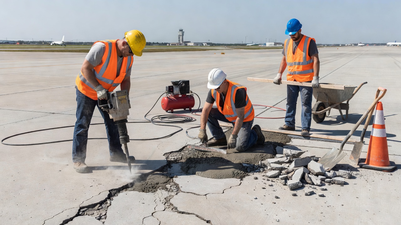
Partial-Depth Patching is the primary repair method for spalling confined to the upper portion of the slab — typically the upper one-third to one-half of the slab thickness. It is appropriate for joint spalling, corner spalling, and surface spalling that does not involve structural compromise of the slab. The standard procedure, per FAA AC 150/5380-6C Appendix A8, ACPA guidelines, and FDOT Airfield Pavement Distress Repair Manual, involves:
Making vertical saw cuts to a minimum depth of 50 mm (2 inches), extending 75 mm (3 inches) beyond the limits of the repair area. The repair area must be rectangular. All unsound concrete and at least 12 mm (1/2 inch) of visually sound concrete must be removed to ensure adequate bond. The repair area is cleaned with high-pressure water and allowed to dry. A new joint sealant reservoir is formed between the repair area and the adjacent slab. The patch material is placed, finished to match the adjacent pavement texture, and cured per manufacturer’s recommendation. Joint sealant is then placed, and traffic is excluded until the material has set.
Minimum patch dimensions per ACPA: minimum length 300 mm (12 inches), minimum width 100 mm (4 inches). Patches must extend 75–100 mm (3–4 inches) beyond delamination marks or visible spalls. If two patches will be less than 600 mm (2 ft) apart, they should be combined into one larger patch. If more than two spalls are present along a transverse joint, the entire joint length should be repaired.
Spalls smaller than 50 mm × 150 mm do not affect ride quality and do not require partial-depth repair — they can be filled with joint sealant.
Partial-depth repair is not appropriate when: the spalling extends through more than half the slab thickness; the cause is D-cracking, ASR, or dowel bar corrosion (unless all metal is removed); the spall exposes reinforcing steel or load transfer devices that cannot be fully removed; or the slab shows substantial fatigue cracking indicating overall structural deterioration.
Repair Materials for Partial-Depth Patching vary by application requirements:
Material
Setting Time
Key Characteristics
Normal PCC (Type I cement)
24+ hours
Use when extended traffic exclusion is possible
High-early-strength PCC (Type III cement)
4–8 hours to 21 MPa
For early opening to traffic
Magnesium phosphate cement
~10 minutes working time
Very fast; cannot use with limestone aggregates
Gypsum-based (calcium sulfate) cement
Rapid
May not perform well in moisture + freeze-thaw exposure
Epoxy-resin mortar / polymer concrete
Variable
Excellent adhesion; do NOT use if steel corrosion is the cause
Proprietary rapid-setting materials
Per manufacturer
Very temperature-sensitive; follow manufacturer’s instructions
Joint Sealing is the primary preventive intervention for early-stage spalling and is essential for preventing future spalling. The procedure involves cleaning joints with compressed hot air, routing joints to the required width and depth if necessary, ensuring clean and dry joint faces, installing backer rod, applying sealant uniformly from bottom to top of joint, and maintaining the sealant surface 3–6 mm (1/8–1/4 inch) below the existing pavement surface. Proper joint sealing prevents water infiltration and incompressible material accumulation — the two primary drivers of joint spalling.
Full-Depth Repair is required when spalling is associated with structural distress, D-cracking, ASR, deep corrosion of load transfer devices, or when partial-depth repair is insufficient. The procedure involves full-depth saw cuts at least 600 mm (2 ft) beyond the repair limits, complete removal of the slab section, restoration of subgrade or base if required, installation of deformed tie bars and dowel bars to restore load transfer, and placement of new concrete. Full-depth repair is significantly more disruptive and costly than partial-depth repair, underscoring the importance of early detection and intervention.
Full Slab Replacement is used when multiple cracks with spalling, extensive slab deterioration, or D-cracking throughout the slab make partial or full-depth patching uneconomical relative to replacement.
Sequencing in Concrete Pavement Rehabilitation (CPR) Projects: The standard sequence is: partial-depth repair → full-depth repair → diamond grinding → joint resealing. This sequence ensures that structural repairs are completed before surface finishing, and that joint resealing is the final step to protect the restored pavement.
Impact on Aircraft Operations and Structural Integrity
Spalling affects aircraft operations through several direct and progressive mechanisms.
Direct Safety Hazards include tire damage from sharp-edged fragments, FOD ingestion by jet engines, aircraft structure damage from propelled fragments, and reduced ride quality during ground operations. High-speed ground operations amplify the impact of surface irregularities: at takeoff speeds, even small surface steps or voids transmit significant shock loads to landing gear. High-severity spalling is explicitly defined as creating a “tire damage hazard” under ASTM D5340 — the standard’s most urgent category.
Friction and Drainage Effects: While spalling itself does not directly reduce friction coefficients, the associated joint deterioration and surface irregularity can affect drainage patterns and create localized areas of poor skid resistance. Water pooling in spalled areas contributes to aquaplaning risk during wet conditions. Spalling around embedded runway lighting can compromise both the structural integrity of the light fitting and the drainage of the light recess.
Progressive Structural Degradation: Spalling at joints exposes the interior of the joint to accelerated water infiltration, leading to subgrade weakening, pumping (ejection of subgrade material under traffic), void formation beneath the slab, and ultimately load-related fatigue cracking and structural failure. Compromised load transfer at spalled joints leads to differential deflection between adjacent slabs — a condition called faulting — which accelerates fatigue cracking and further joint deterioration. Neglected low-severity spalls progressively worsen: the FHWA LTPP data consistently shows that unrepaired low-severity spalls grow into medium and high-severity conditions within 3–7 years in climates with significant freeze-thaw cycling.
Operational and Economic Consequences: Unscheduled replacement of aircraft components damaged by spall-generated FOD results in significant direct costs for aircraft operators. Engine inspections triggered by suspected FOD ingestion require aircraft grounding. Runway closures for major spalling repair disrupt airport operations, reduce capacity, and impose costs on airlines and passengers. The FAA’s guidance is unambiguous: early preventive maintenance is dramatically more cost-effective than deferred repair. A pavement with a PCI of 70 can typically be rehabilitated for a fraction of the cost of the same pavement allowed to deteriorate to a PCI of 40.
Runway Operational Restrictions: Severe or widespread spalling may necessitate runway closure, temporary speed restrictions for ground operations, or downgrading of runway licensing under ICAO Code classification. In extreme cases — particularly where blowups are imminent or have occurred — immediate pavement closure is required. Blowups, the most severe consequence of joint compression failure driven by the same incompressible infiltration that causes spalling, always require immediate closure and emergency repair.
Differential Diagnosis: Distinguishing Spalling from Similar Defects
Accurate identification of spalling — as opposed to visually similar defects — is essential for correct PCI scoring and repair selection.
Defect
Key Distinction from Spalling
Scaling
Shallow, widespread loss of surface mortar and fine aggregate; not discrete fragment breakout at joints; does not produce large loose pieces
Corner Break
Crack extends vertically through full slab thickness; spall fracture plane intersects joint at an angle
D-Cracking
Crescent-shaped hairline cracking pattern near joints; dark discoloration; if spalling results, only D-cracking is recorded
Blowup / Buckling
Upward displacement of slab at joint; far more severe than spalling; always requires immediate closure and repair
Popouts
Individual aggregate pieces pop out of the surface away from joints; caused by freeze-thaw of absorbent aggregates
Fraying
Material is no longer in place along a joint; fraying indicates material has been lost; spalling indicates material may or may not be missing
Patch
If spall has been fully repaired with patching material, record as a patch (not spalling); if boundaries visible, also record as high-severity spall
Key Technical Specifications Reference
The following table summarizes the most important technical parameters for spalling assessment and repair across the major applicable standards:
Parameter
Value / Standard
Joint spalling zone — airfields (PAVER/FAA)
Within 2 ft (600 mm) of joint face
Joint spalling zone — roads (FHWA LTPP)
Within 300 mm of joint face
Low severity spall width (FHWA LTPP)
< 75 mm to joint face, with material loss
Moderate severity spall width (FHWA LTPP)
75–150 mm to joint face, with material loss
High severity spall width (FHWA LTPP)
> 150 mm to joint face, with material loss
Minimum recordable spall length (FHWA LTPP)
100 mm (0.1 m)
Spall not requiring repair (ACPA)
< 50 mm × 150 mm; fill with sealant
Partial-depth repair minimum saw cut depth
50 mm (2 inches)
Partial-depth repair extension beyond distress
75 mm (3 inches)
Minimum patch length (ACPA)
300 mm (12 inches)
Minimum patch width (ACPA)
100 mm (4 inches)
Combine patches if gap less than
600 mm (2 ft)
Full-depth repair saw cut extension
≥ 600 mm (2 ft) beyond repair limits
Sealant surface below pavement (finished)
3–6 mm (1/8–1/4 inch)
Airfield PCC slab joint spacing
4.5–7.5 m (15–25 ft)
PCI scale
0 (failed) to 100 (perfect)
FAA design pavement life
Minimum 20 years (with regular maintenance)
Corner break vs. corner spall threshold
Crack intersects joint < 600 mm from corner = likely spall
Faulting severity upgrade (PAVER)
≥ 3 mm faulting = upgrade one level; > 13 mm = high severity
Primary airfield PCI standard
ASTM D5340 (current: D5340-23)
NATO/military airfield PCI standard
STANAG 7181 ED 1 RD 1
ICAO maintenance reference
ICAO Doc 9137 Part 9
FAA maintenance AC
FAA AC 150/5380-6C
Applicable Standards and References
The assessment, classification, and repair of spalling in airport and infrastructure pavements is governed by a comprehensive body of standards from ICAO, FAA, ASTM, FHWA, and national civil aviation authorities:
ASTM D5340 (Standard Test Method for Airport Pavement Condition Index Surveys) — the definitive standard for airfield PCI surveys, implementing the PAVER distress identification and scoring methodology. Current edition: D5340-23.
STANAG 7181 ED 1 RD 1 — NATO standard for airfield pavement condition index surveys, equivalent to ASTM D5340 for military airfields.
FHWA-HRT-13-092 (Distress Identification Manual for the Long-Term Pavement Performance Program, 5th Revised Edition, 2014) — the standard for distress identification and measurement on road and highway concrete pavements.
FAA AC 150/5380-6C (Guidelines and Procedures for Maintenance of Airport Pavements, 2014) — the primary FAA guidance document for airport pavement maintenance, including spalling identification, severity classification, and repair procedures.
FAA AC 150/5320-17A (Airfield Pavement Surface Evaluation and Rating Manuals, 2014) — provides the simplified PASER visual rating system for general aviation airports.
FAA AC 150/5320-6G (Airport Pavement Design and Evaluation, 2021) — the primary FAA design standard for airport pavements, establishing joint spacing, slab thickness, and structural life requirements.
FAA AC 150/5380-7 (Airport Pavement Management Program, current edition) — establishes requirements for Airport Improvement Program (AIP) funded airports to maintain a pavement management program, including regular PCI surveys.
ICAO Doc 9137, Part 9 (Airport Services Manual — Airport Maintenance Practices, First Edition, 1984) — the primary ICAO technical reference for airport pavement maintenance procedures.
ICAO Doc 9137, Part 2 (Airport Services Manual — Pavement Surface Conditions) — covers friction measurement and surface condition assessment.
ICAO Doc 9157, Part 3 (Aerodrome Design Manual — Pavements) — the ICAO design standard for aerodrome pavements.
ICAO Annex 14, Volume 1 (Aerodrome Design and Operations, current edition) — the primary international standard for aerodrome certification, establishing mandatory requirements for movement area surface condition and FOD control.
ACPA (American Concrete Pavement Association) — Guidelines for Partial-Depth Spall Repair — industry guidance for concrete pavement repair, widely referenced in FAA and state DOT maintenance manuals.
Frequently Asked Questions
Spalling is the loss, breaking, chipping, or fraying of concrete material from the surface or along the edges of joints, cracks, or slab corners. Unlike a full-depth crack, a spall intersects the joint or crack at an angle rather than vertically, and typically does not penetrate the entire slab thickness. It is classified as a distinct distress type in all major pavement condition assessment standards, including ASTM D5340 and ICAO Doc 9137.
Spalling generates loose concrete fragments that become foreign object debris (FOD) on the movement area. FOD can be ingested by jet engines — causing compressor blade damage, engine surge, or flameout — or strike and puncture aircraft tires at high speed, potentially causing loss of directional control during takeoff or landing. High-severity spalling is explicitly classified as creating a 'tire damage hazard' under ASTM D5340 / FAA PAVEAIR.
The most common cause is infiltration of incompressible materials (sand, grit, stone fragments) into open joints. When the slab expands in hot weather, the incompressibles prevent joint closure and generate crushing pressure at the joint face. Other causes include dowel bar corrosion, freeze-thaw cycling, poor concrete quality, late sawing of contraction joints, and failure to maintain joint sealant.
Under ASTM D5340 (PAVER/FAA PAVEAIR), joint and corner spalling is classified into three severity levels: Low (little or no FOD potential), Medium (some FOD potential, loose fragments present), and High (definite FOD hazard or tire damage hazard from displaced pieces). The FHWA LTPP system uses spall width to face of joint: Low < 75 mm, Moderate 75–150 mm, High > 150 mm.
The primary method is partial-depth patching. The procedure involves sawing vertical cuts to a minimum depth of 50 mm (2 inches), extending 75 mm (3 inches) beyond the distress limits, removing all unsound concrete, cleaning the area, placing a rapid-setting or high-early-strength concrete patch, and restoring the joint sealant reservoir. Full-depth repair or slab replacement is used when spalling extends through a significant portion of slab thickness or is caused by D-cracking or ASR.
ICAO Doc 9137 Part 9 (Airport Maintenance Practices) covers pavement repair procedures including joint, edge, and corner repair. ICAO Annex 14 requires that movement area surfaces be kept free of loose stones and FOD. The ICAO-endorsed PCI methodology (ASTM D5340) is the standard tool for quantifying spalling and other distresses. ICAO also endorses the PCN/PCR system for pavement strength rating, which can be downgraded when spalling indicates structural deterioration.
Scaling is the loss of surface mortar and fine aggregate over a broad, shallow area — it does not involve discrete fragment breakout at joints. Spalling involves larger, deeper breakout of material, typically at or near joints, cracks, or corners, and produces loose fragments. Severe scaling may progress into surface spalling, but the two are recorded as separate distress types in PCI surveys.
In airfield PCI surveys (ASTM D5340 / PAVER), joint spalling and corner spalling are measured by the number of slabs affected at each severity level (Low, Medium, High). In road surveys (FHWA LTPP), longitudinal and transverse joint spalling is measured in meters of affected joint length. The spall zone is defined as within 2 ft (600 mm) of the joint face for airfields, and within 300 mm for highway surveys.
Keep Your Runway Defect-Free
Detect spalling and other pavement defects early with TarmacView's AI-powered inspection platform — before they become FOD hazards or costly structural failures.
Joint spalling is the cracking, breaking, or chipping of concrete slab edges at transverse or longitudinal joints in PCC pavements. It occurs when incompressibl...
A shattered slab is a portland cement concrete (PCC) pavement slab broken into four or more pieces by intersecting cracks, representing the terminal structural ...
A blowup is a localized upward buckling or shattering of concrete pavement at a transverse joint or crack during hot weather, caused when compressive stresses f...
25 min read
Concrete Defects
Pavement Distress
+3
Cookie Consent We use cookies to enhance your browsing experience and analyze our traffic. See our privacy policy.