Suspension Cable
Suspension bridge main cables are the primary load-carrying catenary cables from which the deck is suspended via vertical hanger ropes. Main cable condition — c...
27 min read
Bridges
Cable Inspection
+3
Stay cables are high-strength steel tension elements connecting the bridge pylon to the deck in cable-stayed bridges, forming the primary load path. Cable condition — corrosion, wire breaks, vibration, anchorage deterioration — is critical for structural safety. Covers cable types, corrosion protection systems, inspection methods, and stay cable replacement.
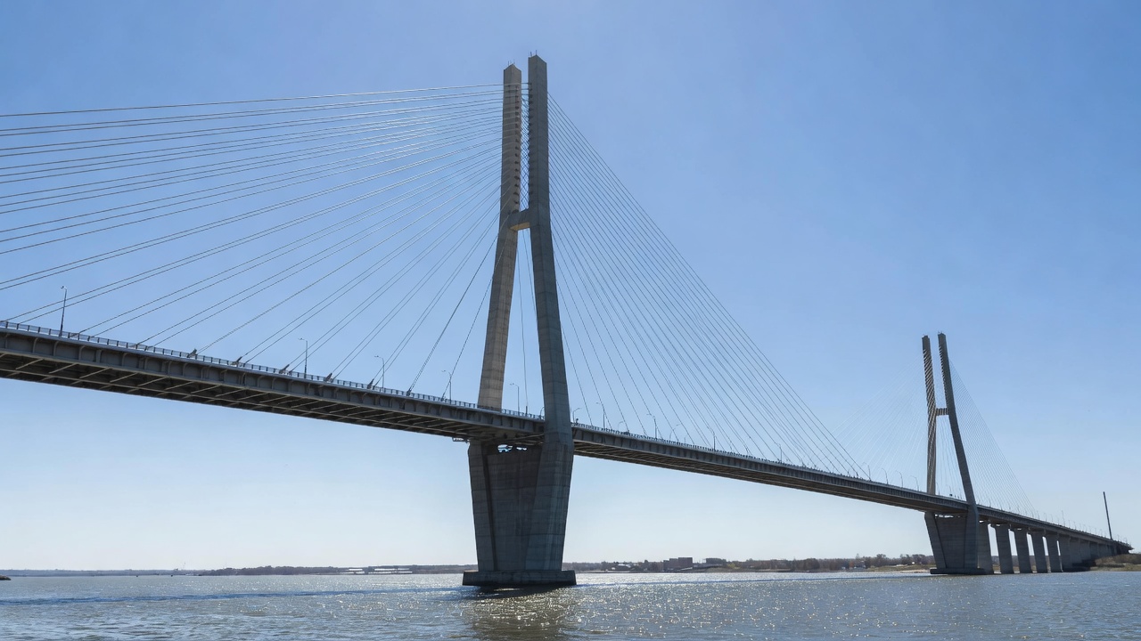
A stay cable is a high-strength steel tension member that directly connects the bridge tower (pylon) to the deck girder in a cable-stayed bridge. It forms the structural backbone of the bridge’s load path, transferring gravity loads from the deck — including self-weight, traffic, and superimposed dead loads — to the pylon and ultimately to the foundation. Unlike suspension bridge cables that are draped over towers and anchored at the ends, stay cables are individually anchored at both ends (pylon and deck), are typically inclined at angles between 20 and 60 degrees from horizontal, and act as continuous elastic supports for the deck girder.
{{
The structural behavior of a cable-stayed bridge is fundamentally governed by the stay cables. The cables create a triangulated system with the pylon and deck, producing a structure that behaves similarly to a continuous beam on elastic supports. The equivalent modulus of elasticity of a stay cable — which accounts for the cable’s sag under its own weight — was formulated by Ernst and is a critical design parameter. Longer, more sagging cables have a reduced effective modulus, which affects load distribution across the bridge. The cable force in each stay is a function of the geometry, dead load, live load position, and temperature, and the forces are typically adjusted during construction through a process called staged construction analysis with force control or geometry control methods.
Stay cables are classified as primary structural members under bridge design codes including AASHTO, and are subject to rigorous fatigue design criteria. The AASHTO LRFD Bridge Design Specifications require stay cables to be designed for a fatigue life exceeding 2 million cycles, with stress ranges depending on the cable type and detailing category. The Post-Tensioning Institute (PTI) publishes the Recommendations for Stay Cable Design, Testing, and Installation, which serves as the primary industry standard in North America for stay cable systems.
Several distinct types of stay cables have been used in cable-stayed bridge construction worldwide, each with specific mechanical properties, corrosion protection characteristics, and fatigue performance.
{{
Parallel Strand Systems are the most widely used stay cable type in modern construction. They consist of multiple 7-wire prestressing strands (typically 15.2 mm or 15.7 mm diameter, Grade 270 or Grade 1860) running parallel to each other inside a common outer HDPE sheath. Each strand is individually protected with grease and an extruded PE sheath (monostrand system), providing a multi-barrier corrosion protection approach. The number of strands per cable varies from as few as 12 on small bridges to over 100 on major spans. Strands are individually stressed using lightweight monostrand jacks, which simplifies construction and allows strand-by-strand replacement. Parallel strand systems offer high fatigue resistance, field-proven reliability, and ease of handling. The VSL SSI 2000, DYWIDAG, and Freyssinet stay cable systems are prominent examples.
Parallel Wire Systems consist of individual 5 mm or 7 mm diameter wires (ASTM A421) arranged in a hexagonal or circular pattern and encased in a PE or steel pipe, with the interstices filled with cementitious grout. These systems were used extensively in early cable-stayed bridges including the Pasco-Kennewick Bridge (1978) and the Sunshine Skyway Bridge (1987). Parallel wire cables offer high stiffness and compact cross-sections. However, they are no longer commercially available in the United States according to FHWA Technical Advisory 5140.25. A significant limitation is that individual wires cannot be replaced — if deterioration occurs, the entire cable must be replaced.
Locked Coil Strands are pre-formed helical strand cables where individual wires are shaped to interlock, creating a dense, compact cross-section with a smooth outer surface. The outer wires are typically Z-shaped (locked) to prevent moisture ingress and hold the inner wires in compression. Locked coil strands were used in early cable-stayed bridges including the Lake Maracaibo Bridge in Venezuela (1962) and the Kurt Schumacher Bridge in Mannheim, Germany. They offer excellent corrosion resistance due to their dense arrangement but have variable stress-strain behavior and lower fatigue resistance compared to parallel strand systems. According to FHWA guidance, locked-coil and structural strands are no longer used for stay cables in the United States.
CFRP (Carbon Fiber Reinforced Polymer) Stay Cables represent an emerging technology that replaces steel with carbon fiber composite material. CFRP cables offer corrosion immunity, very high strength-to-weight ratio (approximately 5 to 7 times that of steel), excellent fatigue performance, and negligible creep. The first road bridge to use CFRP stay cables was the Stork Bridge in Winterthur, Switzerland (1996), followed by several pedestrian bridges in Japan and Europe. CFRP cables are significantly lighter than steel cables of equivalent strength, reducing pylon and foundation loads. However, they have lower modulus of elasticity (approximately 160 GPa compared to 205 GPa for steel), different anchorage requirements, and significantly higher material costs. CFRP stay cables remain a niche application but show promise for very long-span bridges where weight reduction becomes critical.
Corrosion protection is the most critical durability consideration for stay cables. The high tensile stress in stay cables (typically 40% to 55% of ultimate tensile strength under dead load) makes them susceptible to stress corrosion cracking (SCC) and hydrogen embrittlement, particularly in aggressive environments with chlorides. Modern stay cables employ multi-barrier corrosion protection systems with multiple independent layers of protection.
The HDPE Outer Sheathing (high-density polyethylene pipe) is the first line of defense. According to FHWA guidance, HDPE provides an excellent vapor barrier — a 6 mm thick HDPE sheath has the same vapor transmission resistance as a 10.7 m thick concrete wall. However, black HDPE has a thermal coefficient of expansion approximately six times that of steel and grout, necessitating the application of white or light-colored Polyvinyl Fluoride (PVF) tape wrapping to control temperature variations and reduce thermal differential stresses. HDPE sheathing also provides the form for injected cementitious grout and protects the underlying corrosion protection layers from UV degradation and mechanical damage.
Cementitious Grout injected into the annular space between the HDPE pipe and the strand bundle provides an alkaline environment (pH > 12.5) that passivates the steel surface and prevents corrosion. However, extensive research at the University of Texas at Austin (Hamilton, Breen, and Frank, 1995) demonstrated that grout in stay cables is susceptible to shrinkage cracking and air void formation. When the outer HDPE sheath is breached, cracks in the grout provide a direct path for corrosive agents to reach the steel strands. The research showed that corrosion could occur within days of a sheath breach when exposed to saline environments. Modern grout formulations include expansive admixtures (such as aluminum powder), silica fume for reduced permeability, and corrosion inhibitors such as calcium nitrite.
Wax and Grease Systems provide an alternative or supplementary corrosion protection medium. Individual monostrands in modern parallel strand systems are coated with a petroleum-based wax or grease before the individual PE sheath is extruded over them. The wax — typically a soft petroleum-based material with a melting point exceeding 260°C — displaces moisture from the steel surface and provides continuous protection even under cyclic loading. Grease-filled systems function similarly, using lithium-based or calcium-based greases. In anchorage zones, wax or grease filling within the anchorage cap provides corrosion protection for the wedges, strand tails, and bearing plate.
Dehumidification Systems represent the most advanced corrosion protection approach for stay cables. A dry air dehumidification system continuously circulates low-humidity air (typically less than 40% relative humidity) through the interior of the cable system. The dehumidified air is injected at the anchorage and flows through the annular space between strands, exiting through small vents near the pylon anchorage. Dehumidification systems have been installed on major bridges including the Øresund Bridge (Denmark-Sweden), the Stonecutters Bridge (Hong Kong), and the Russky Bridge (Russia). These systems virtually eliminate the risk of corrosion by maintaining a relative humidity below the threshold required for electrochemical corrosion reactions. Monitoring sensors provide real-time feedback on humidity levels within each cable.
The PTI Recommendations for Stay Cable Design, Testing, and Installation (currently in its 6th edition) provides detailed requirements for corrosion protection system qualification. Section 4 of PTI Recommendations addresses corrosion protection, requiring that all stay cable systems pass a 500-hour salt spray test (ASTM B117) with no corrosion products, a 30-cycle accelerated weathering test (ASTM G154 or ISO 4892), and a sustained-load corrosion test. The PTI recommendations also prohibit the use of galvanized strand in direct contact with cementitious grout due to the risk of hydrogen evolution and accelerated zinc corrosion in alkaline environments.
Stay cable inspection is a specialized, high-consequence task requiring a combination of visual assessment, non-destructive testing (NDT), and robotic technologies. The National Bridge Inspection Standards (NBIS) require inspection of all bridges every 24 months, but stay cables present unique accessibility challenges that conventional inspection cannot fully address.
Visual Inspection is the first level of assessment. Inspectors examine the external HDPE sheathing for cracks, cuts, abrasion, discoloration, bulging, or UV degradation. The sheathing condition provides indirect evidence of the internal cable condition — a cracked sheath may allow moisture ingress, while localized bulging can indicate internal corrosion expansion. Visual inspection of the anchorage zone requires removing protective caps to examine the bearing plate, wedges, strand tails, and any corrosion protection filler materials. Hammer-tap surveys are conducted on the HDPE pipe to map voids in the cementitious grout — hollow-sounding areas indicate incomplete grout filling, which are vulnerable locations for corrosion initiation.
Magnetic Flux Leakage (MFL) Testing is the primary NDT method for detecting broken wires and section loss in steel stay cables. MFL works by magnetizing the steel cable using a strong magnetic field (typically generated by permanent magnets or electromagnets) and then scanning for magnetic flux that “leaks” from the cable at locations of cross-sectional reduction. The method can detect individual wire breaks, localized corrosion pitting, and generalized section loss. MFL sensors are typically integrated into a scanning device that travels along the cable length, either manually deployed or mounted on a robotic crawler. The FHWA-funded research in the 1990s developed the Magnetic Field Perturbation Method (MPC) specifically for stay cable inspection. However, the presence of steel pipe sheathing seriously inhibits or prevents the successful use of MFL equipment, as noted in FHWA Technical Advisory 5140.25.
Radiographic Testing (X-ray or gamma-ray) provides detailed internal imaging of the cable cross-section. It can detect broken wires, corrosion pitting, grout voids, and strand position irregularities. Radiography requires access to both sides of the cable for film placement and radiation source positioning, which can be challenging for elevated cables. Modern digital radiography systems reduce exposure times and provide immediate image analysis, but the safety requirements for radiation control limit the application to specific locations (typically anchorage zones) rather than full-length scanning.
Acoustic Emission (AE) Monitoring detects the high-frequency elastic waves generated by wire breaks in stay cables. When a stressed steel wire fractures, it releases a burst of energy that propagates through the cable and structure. AE sensors mounted at the cable ends (deck and pylon anchorages) detect these events and, through time-of-flight analysis of signal arrival at multiple sensors, can locate the break position along the cable length. Continuous AE monitoring systems provide real-time surveillance of wire break activity, enabling bridge owners to track deterioration rates and make informed decisions about intervention timing. The SoundPrint® system developed by Pure Technologies (now part of Xylem) is a widely deployed fiber-optic AE monitoring solution installed on numerous major bridges worldwide.
Ultrasonic Guided Wave Testing uses low-frequency ultrasonic waves (typically 20-100 kHz) that propagate along the length of the cable. The guided waves interact with corrosion, wire breaks, and section changes, and the reflected waves can be analyzed to locate and characterize defects. Guided wave testing is particularly effective for inspecting the anchorage zone, where access is limited and conventional ultrasonic testing (UT) of individual wires is impractical. Guided wave systems can typically inspect 10-30 m of cable from a single sensor location.
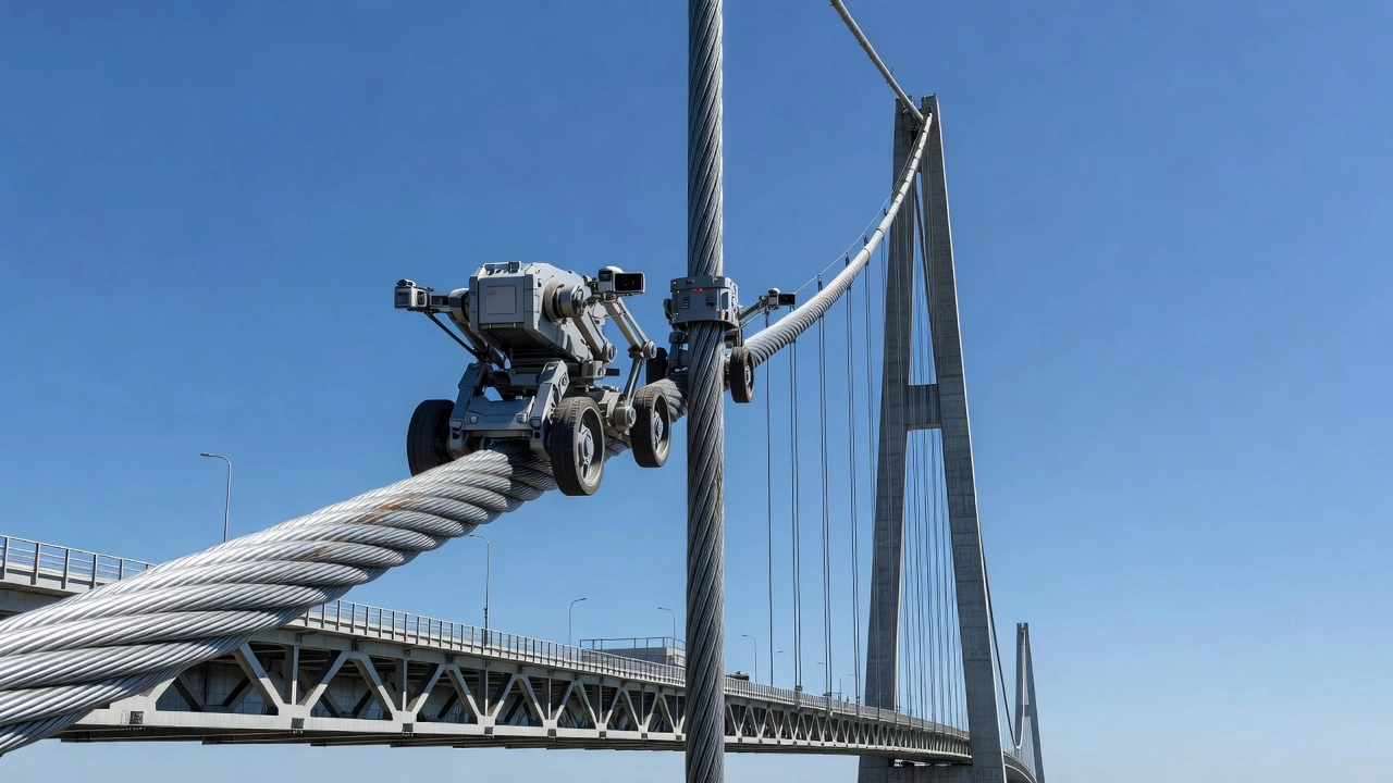
Robotic and Climbing Inspection Systems have been developed to address the significant accessibility challenges of stay cable inspection. Cable-climbing robots use wheel-driven or track-driven mechanisms that travel the length of the cable, carrying MFL sensors, cameras, and other NDT equipment. Notable examples include the CableClimber robot developed at Carnegie Mellon University and the SMA (Steel Maidens) robot developed in Japan. The robot platforms can carry MFL sensor arrays, high-resolution cameras, and ultrasonic thickness gauges while autonomously climbing cables at speeds of 5-10 m/min. More recently, drone-based inspection using high-resolution cameras and thermal imaging has been deployed for external sheathing condition assessment.
Stay cable vibration is a critical serviceability and fatigue concern in cable-stayed bridges. Modern stay cables are long, lightweight, and have inherently low structural damping (logarithmic decrement typically 0.001 to 0.005), making them susceptible to wind-induced vibrations. The FHWA study Wind-Induced Vibration of Stay Cables (FHWA-HRT-05-083) identified five principal vibration mechanisms.
Rain-Wind Induced Vibration (RWIV) is the most widely documented vibration phenomenon in stay cables. It occurs when moderate wind speeds (typically 8-15 m/s) combine with light rain. The rain forms a water rivulet on the upper surface of the inclined cable, which changes the cable’s aerodynamic cross-section. The water rivulet oscillates around the cable circumference at a frequency that can lock into the cable’s natural frequency, producing large amplitude vibrations with peak-to-peak displacements that can exceed several cable diameters. RWIV was first systematically documented on the Meiko-Nishi Bridge in Japan in the 1980s and has been observed on numerous bridges worldwide. The critical condition occurs for cable diameters between 100-200 mm, with inclination angles of 15-45 degrees from horizontal.
Dry Inclined Cable Galloping is a vibration mechanism that occurs under dry conditions (no rain) when the relative wind-cable angle produces aerodynamic instability. Unlike classical galloping of bluff bodies, dry inclined cable galloping is associated with the cable’s critical Reynolds number range and the formation of an axial flow along the cable axis. The FHWA study identified this as the most critical wind-induced vibration mechanism requiring further research.
Vortex-Induced Vibration (VIV) results from the periodic shedding of vortices from the cable surface at specific wind speeds. The vortex shedding frequency is given by the Strouhal relationship: f = St × U/D, where St is the Strouhal number (approximately 0.2 for circular cylinders), U is wind speed, and D is cable diameter. When the vortex shedding frequency coincides with one of the cable’s natural frequencies, resonance can occur. VIV amplitudes are typically smaller than RWIV but can be sustained over a wider range of wind speeds.
Wake Galloping occurs when a downstream cable lies in the aerodynamic wake of an upstream cable in a cable group. The downstream cable experiences unsteady aerodynamic forces that can produce large oscillations. Wake galloping is a concern for closely spaced cables in multi-cable arrangements.
Mitigation Methods for stay cable vibration include several approaches. Hydraulic Dampers (viscous or viscoelastic) are installed near the deck anchorage, typically at 1-3% of the cable length from the deck, providing supplemental damping to reduce vibration amplitudes. The damper design must consider the optimum damping coefficient for the Scruton number, which represents the ratio of structural damping to aerodynamic excitation. Cross-ties (also called cross-cables) connect adjacent stay cables at intermediate points along their length, transferring energy between cables and increasing the effective damping of the system. The Leonard P. Zakim Bunker Hill Bridge in Boston uses cross-ties for its shorter back-stay cables. Helical Fillets (also called helical wires or ribs) are spiraling surface projections applied to the HDPE sheathing that disrupt the formation of water rivulets and are highly effective for RWIV mitigation. Surface texturing with dimples or grooves has also been used. Tuned Mass Dampers (TMDs) and Tuned Liquid Dampers (TLDs) have been applied on specific bridges where conventional dampers were insufficient. The Fred Hartman Bridge in Texas and the Veterans’ Memorial Bridge in Louisiana both experienced significant cable vibrations that required retrofit damper installations.
The anchorage zones — at both the deck and pylon ends — are the most vulnerable and critical locations for stay cable deterioration. The DYWIDAG Stay Cable Anchor Zone Inspection service notes that moisture entering the anchor zone due to degraded sealing or ineffective drainage can lead to standing water and long-term corrosion that develops internally and may not be visible during routine inspections.
{{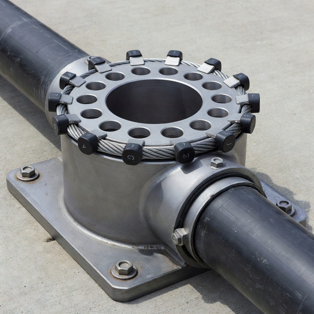
The lower (deck) anchorage is particularly susceptible to corrosion. Condensation forming inside the cable system naturally flows downward and accumulates at the lowest point when drainage is inadequate. The anchorage zone contains the critical load transfer components: the anchor block (or anchor head), wedges that grip each strand or wire, the bearing plate that distributes the cable force to the structure, and the transition pipe between the cable free length and the anchor block. Corroded wedges can reduce the anchoring force by allowing strands to slip, and wire fractures near the wedge grip zone can occur without visible external signs.
Anchorage inspection typically requires removal of the protective cap and extraction of the corrosion protection filler material (wax, grease, or grout in the cap). Endoscopic inspection using flexible borescopes allows visual examination of the wedge area and the transition zone between the anchor and the free length of the cable. Ultrasonic Testing (UT) of the individual strands or wires near the anchorage can detect corrosion pitting and partial fractures from the accessible end. DYWIDAG offers specialist inspection using ultrasonic testing to detect broken or partially fractured wires and areas affected by advanced corrosion. Where accessible, wedges at the anchor plate surface are inspected using endoscopic tools.
The PTI Recommendations require that anchorage systems be designed with inspectability in mind. The anchorage cap should be removable for inspection, and the corrosion protection filler should be selected to facilitate removal and replacement during inspection cycles. The PTI recommendations also require that the anchorage zone be tested for watertightness during system qualification.
The tensile force in stay cables is a critical parameter for bridge structural health assessment. Changes in cable force can indicate structural damage, foundation settlement, strand slippage, or deterioration of the tension elements. Three primary methods are used for stay cable force measurement.
The Lift-Off Test is the most direct and accurate method. A hydraulic jack is installed over the existing anchorage, and the cable is incrementally jacked until the bearing plate lifts off from the supporting structure. The force at which lift-off occurs is recorded from a calibrated pressure gauge or load cell. The lift-off test directly measures the cable force with accuracy typically within ±2%. However, it requires specialized equipment, access to the anchorage, and the capacity to temporarily apply forces potentially exceeding the existing cable load. Methods for isolating the structure during this test are specified in PTI Recommendations.
The Vibration Method uses the relationship between a cable’s natural frequency and its tensile force. The cable is modeled as a tensioned string with bending stiffness, and its natural frequencies are related to tension by the equation: T = 4mL²f₁² (for the fundamental mode, neglecting bending stiffness), where T is tension, m is mass per unit length, L is cable length, and f₁ is the fundamental frequency. Accelerometers mounted on the cable record ambient or forced vibrations, and the frequency spectrum is analyzed to extract natural frequencies. The vibration method is non-invasive, requires no special equipment beyond accelerometers and data acquisition, and can be performed from the deck or ground level. However, accuracy is affected by cable sag, bending stiffness uncertainty, and boundary conditions at the end connections. For long cables with significant sag, the Ernst equivalent modulus correction must be applied.
Direct Load Cell Measurement uses force transducers installed in the load path between the anchor block and bearing plate. Load cells provide continuous real-time force data and are incorporated into Structural Health Monitoring (SHM) systems on major bridges. Ring-type load cells (annular) that fit around the anchor block are commonly used. Load cell accuracy is typically ±1% of full scale, but long-term drift and temperature effects must be considered. Load cell data is transmitted to a central monitoring station via wired or wireless communication systems.
The selection of force measurement method depends on the bridge accessibility, the required accuracy, whether the measurement is one-time or continuous, and the budget. For routine condition assessment, the vibration method is commonly used due to its low cost and ease of deployment, while lift-off testing provides validation measurements on selected cables. Continuous load cell monitoring is reserved for critical cables or structures with known issues.
Wire breaks in stay cables are a critical indicator of structural deterioration. A single wire break in a strand or cable reduces the cable’s cross-sectional area and redistributes stress to adjacent wires, potentially initiating a cascade of further breaks. The detection and quantification of wire breaks is therefore essential for safety assessment.
The acoustic signature of a wire break is distinctive. When a stressed steel wire fractures, it releases a transient elastic wave (acoustic emission) with a characteristic frequency content — typically broad-band energy from 1 kHz to over 500 kHz, with peak energy in the 50-150 kHz range. The duration of the AE event from a wire break is typically 1-10 milliseconds. The energy released is proportional to the wire diameter and the stress level at fracture. A 5 mm wire stressed to 700 MPa releases approximately 10-100 mJ of acoustic energy upon fracture.
Wire breaks can be detected by passive acoustic monitoring (listening for fracture events) or active ultrasonic testing (propagating guided waves and detecting reflections from fracture surfaces). Passive monitoring using acoustic emission sensors provides real-time detection of break events but cannot provide information about pre-existing breaks. Active methods can map the location and severity of existing damage but require access to the cable for sensor installation.
The rate of wire breaks is a critical parameter for risk assessment. A single wire break in a 100-strand cable represents a 1% area loss, which is typically not structurally significant. However, a cluster of breaks in close proximity can create a critical defect. The transition from isolated breaks to accelerated break rates is often associated with the onset of corrosion-induced deterioration. Continuous AE monitoring systems can track the cumulative wire break count over time and alert bridge owners when break rates exceed established thresholds.
The Freyssinet maintenance services brochure notes that acoustic emission surveillance using strategically placed sensors can listen for tell-tale sounds emitted by the energy release when a stressed element breaks. The location of the fracture can be calculated using the timing of recording from adjacent sensors, enabling precise identification of the damaged cable and the break location along its length.
Stay cable replacement is among the most technically challenging bridge rehabilitation operations. It must be performed while maintaining the structural stability of the bridge, and in many cases while the bridge remains open to traffic.
Strand-by-Strand Replacement is the preferred method for parallel strand cable systems. Individual strands are de-tensioned using monostrand jacks, removed, and replaced with new strands, one at a time. The process maintains the overall cable force within acceptable limits because only a small fraction of the cable’s total capacity is affected at any time (typically 1-3% per strand for a 30-50 strand cable). The sequence of strand removal and installation is carefully planned to avoid excessive force redistribution to adjacent cables and to maintain acceptable deck geometry.
The replacement procedure for the Hale Boggs (Luling) Bridge in Louisiana, as documented in a PTI Technical Conference paper, provides a detailed case study. The bridge’s stay cables were replaced strand-by-strand using a custom-designed stressing system. Each cable of 25-45 strands required approximately 2-3 weeks for complete replacement, including strand removal, new strand installation, and final force adjustment. The replacement was executed without closing the bridge to traffic, with lane closures only directly beneath the cable being worked on.
Full Cable Replacement may be required for parallel wire cables, locked coil strands, or cables where the anchorage or sheathing system has deteriorated. Full replacement requires temporary supports or cranes to handle the dead weight of the complete cable (which can be 20-50 tonnes for a long stay cable). The bridge may need to be closed or have reduced live load capacity during replacement. The new cable is typically installed using the same HDPE sheathing and grouting procedures as new construction, with careful attention to force matching with the remaining cables.
Temporary Force Management during replacement is critical. The removal of a cable redistributes its force to adjacent cables, potentially overloading them. Finite element analysis of the entire bridge is performed to determine acceptable replacement sequences. Adjacent cables are monitored continuously during the replacement using vibration-based force measurement or load cells. If forces exceed safe limits, the procedure is halted and additional measures (such as temporary propping or counterweights) are implemented.
Post-Tensioning Institute (PTI) Recommendations require that stay cable systems be designed for replaceability — the anchorage details, HDPE pipe transitions, and structural connections must be configured to allow individual strand removal and replacement without demolition of adjacent structure. This requirement has been incorporated into PTI since the 3rd edition and is now standard practice for all new cable-stayed bridges.
Structural Health Monitoring (SHM) for stay cables has evolved from research applications into mainstream bridge management practice. Modern SHM systems provide continuous, real-time data on cable condition, force, and behavior, enabling data-driven maintenance decisions and early warning of deterioration.
Acoustic Emission Monitoring Systems have become the most widely deployed SHM technology for wire break detection. The SoundPrint® system uses distributed fiber-optic acoustic sensors (or arrays of piezoelectric AE sensors) that listen continuously for the unique acoustic signature of wire fractures. Sensor data is transmitted to a cloud-based processing platform where machine learning algorithms classify events by type (wire break vs. environmental noise) and calculate the location of each event. Systems have been installed on dozens of major bridges worldwide, including the Sunshine Skyway Bridge (Florida), the Kosciuszko Bridge (New York), and the Port Mann Bridge (British Columbia).
Fiber Optic Sensing has advanced significantly for stay cable monitoring. Fiber Bragg Grating (FBG) sensors can be embedded in the cable or attached to the sheathing to measure strain, temperature, and vibration at multiple points along the cable length. Distributed acoustic sensing (DAS) using Rayleigh backscatter in standard telecom fibers provides continuous sensing along the entire fiber path, effectively creating thousands of virtual AE sensors. The DAS technology uses an interrogator unit that launches laser pulses and analyzes the backscattered light to detect vibrations along the fiber. This approach was deployed on the Stonecutters Bridge in Hong Kong for comprehensive stay cable monitoring.
Vibration-Based Monitoring systems continuously track the modal parameters of each stay cable — natural frequencies, damping ratios, and mode shapes. Changes in natural frequency indicate changes in cable force (from strand slippage, thermal effects, or structural redistribution). Changes in damping indicate damper degradation or changes in cable mass (from ice accumulation or internal water ingress). The data from accelerometers mounted on each cable is typically aggregated at 10-50 Hz sampling rates and transmitted to a monitoring center.
Environmental Monitoring systems measure wind speed and direction, temperature, humidity, and precipitation to correlate cable behavior with environmental conditions. This data is essential for identifying the conditions that trigger vibration events and for distinguishing environmentally-induced behavior from deterioration-related changes.
The PTI Recommendations include an appendix on inspection and monitoring that provides guidance on selecting monitoring approaches based on bridge criticality, age, condition, and budget. The recommendations emphasize that SHM does not replace periodic inspection but supplements it by providing continuous data between inspection intervals and by identifying locations that warrant more detailed investigation.
{{
Implement best practices for stay cable inspection, corrosion protection, and structural health monitoring to extend service life and maintain structural safety.
Suspension bridge main cables are the primary load-carrying catenary cables from which the deck is suspended via vertical hanger ropes. Main cable condition — c...
Bridge girders are the primary horizontal load-carrying beams supporting the bridge deck, spanning between piers and abutments. Common types include steel I-gir...
A prestressing tendon is a high-strength steel element — typically seven-wire strand, wire, or bar — used in prestressed or post-tensioned concrete to apply per...