What is a stopway?
Stopway and Declared Distances on Runways
Definition and Purpose
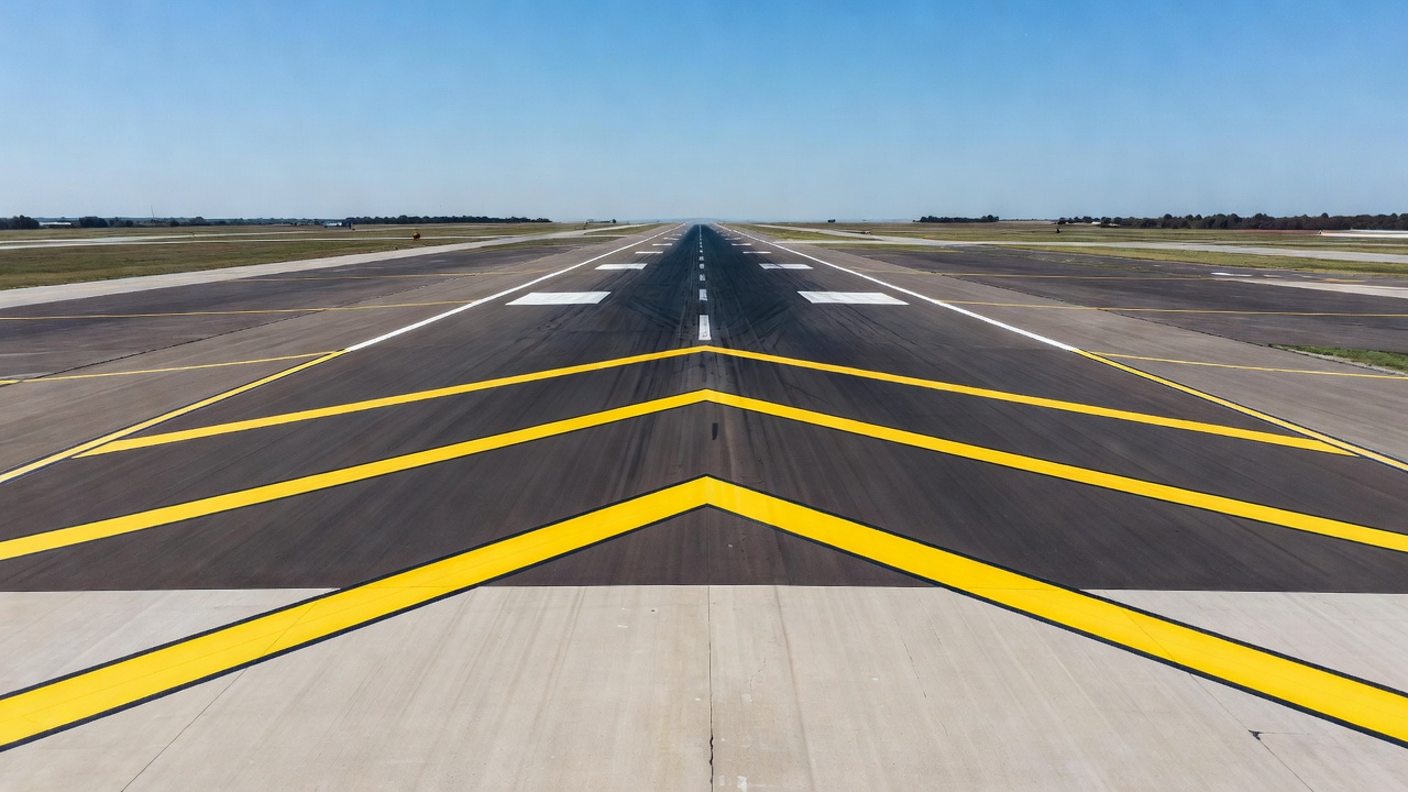
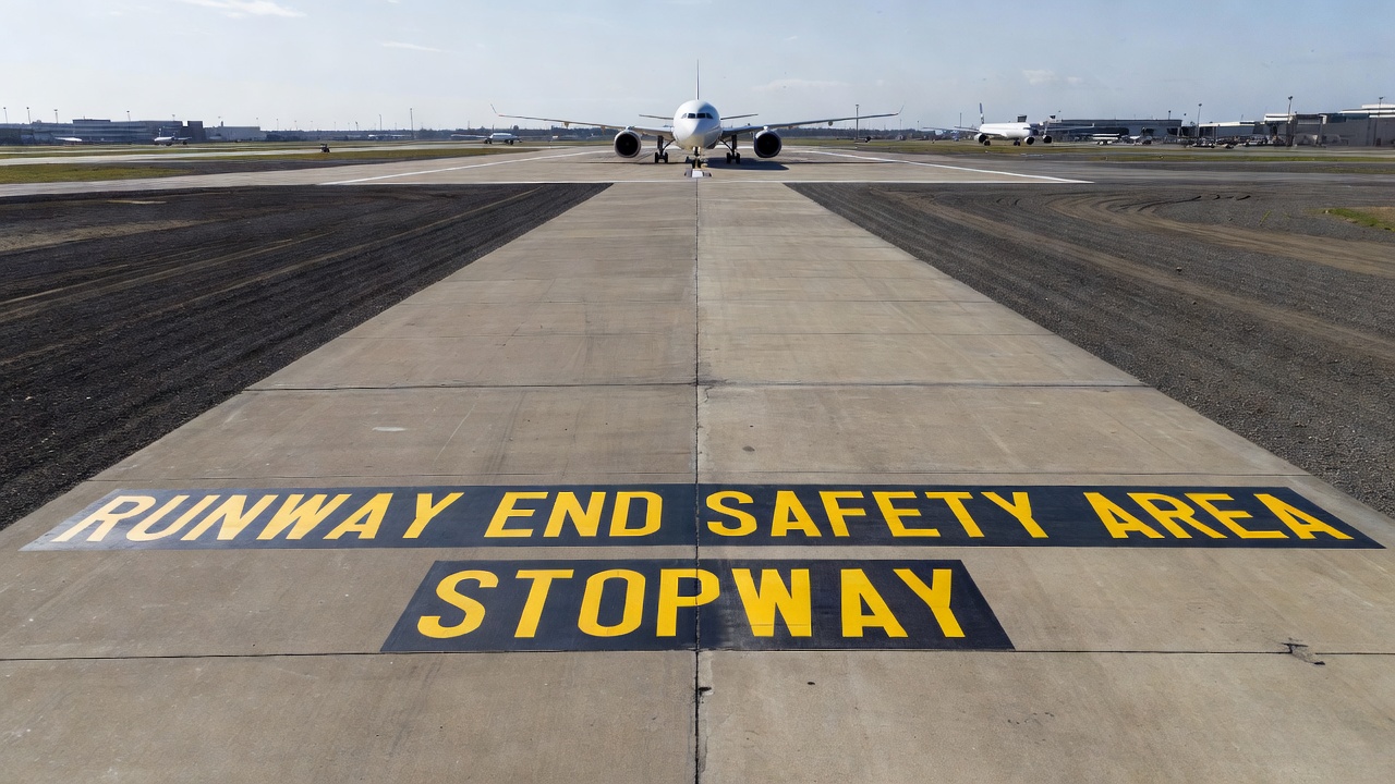
A stopway is a defined rectangular area at the end of a runway, prepared or constructed to support an aircraft during an abandoned (rejected) takeoff without inducing structural damage to the aircraft. The term is formally defined by the International Civil Aviation Organization (ICAO) in Annex 14, Volume I, Chapter 1, Aerodromes. The stopway is not intended for routine takeoff, landing, or taxiing operations, its sole purpose is to provide a deceleration surface in the event that a takeoff is rejected after the aircraft has accelerated past the decision speed V1.
The fundamental difference between a stopway and the runway itself lies in the operational intent. While the runway is engineered for continuous daily use under full takeoff and landing loads, the stopway is designed for occasional emergency use. The stopway extends the Accelerate-Stop Distance Available (ASDA), which is the total distance declared available for an aircraft to accelerate to V1 and, if necessary, abort the takeoff and come to a complete stop. Without a stopway, the ASDA is equal to the TORA. With a stopway, ASDA = TORA + stopway length.
Stopways are primarily found at airports where runway length alone is insufficient to meet the accelerate-stop distance requirements for certain aircraft operations. This situation typically arises at airports constrained by topography, environmental restrictions, or urban development that prevents physical runway extension. By constructing a stopway, airport operators can provide additional safety margin for rejected takeoffs without extending the runway pavement itself, a significantly more expensive and logistically complex undertaking. The design, construction, and maintenance of stopways are governed by the same regulatory frameworks that apply to runways, with some specific exceptions defined by ICAO.
Declared Distances Overview
Declared distances are standardized runway length values published for each runway direction at an airport. They represent the portions of runway and associated areas that are officially available for specific phases of aircraft operations. The four declared distances defined by ICAO Annex 14, Chapter 2, Section 2.8 are:
| Declared Distance | Acronym | Definition | Formula |
|---|---|---|---|
| Takeoff Run Available | TORA | The length of runway declared available and suitable for the ground run of an aeroplane taking off | Physical runway length less any sections not suitable for takeoff ground roll |
| Takeoff Distance Available | TODA | The length of the takeoff run available plus the length of the clearway, if provided | TORA + Clearway |
| Accelerate-Stop Distance Available | ASDA | The length of the takeoff run available plus the length of the stopway, if provided | TORA + Stopway |
| Landing Distance Available | LDA | The length of runway declared available and suitable for the ground run of an aeroplane landing | Physical runway length less displaced threshold sections |
The stopway is included exclusively in the ASDA calculation. It does not affect TORA, TODA, or LDA. This distinction is critical for flight planning and performance calculations. For example, at an airport with a 2,500-meter runway and a 300-meter stopway, the declared distances would be published as:
- TORA: 2,500 m
- TODA: 2,500 m (no clearway in this example)
- ASDA: 2,800 m (2,500 m + 300 m stopway)
- LDA: 2,500 m
The operational significance of ASDA is most apparent during the takeoff performance calculation. Aircraft takeoff performance is governed by three key distances: the takeoff run (ground roll from brake release to liftoff), the takeoff distance (ground roll plus airborne segment to 35 ft or 50 ft obstacle clearance height), and the accelerate-stop distance (distance required to accelerate to V1, reject the takeoff, and decelerate to a full stop). The accelerate-stop distance must not exceed the published ASDA. A longer ASDA, achieved through a stopway, directly increases the maximum allowable takeoff weight for the aircraft or improves safety margins on rejected takeoffs.
The requirements for declaring and publishing declared distances are specified in ICAO Annex 14, Chapter 2, Section 2.8. The aerodrome operator, in coordination with the appropriate national aviation authority (such as the FAA in the United States or the national civil aviation authority in other ICAO member states), determines the declared distances for each runway direction. These values are then published in the national Aeronautical Information Publication (AIP), the FAA Chart Supplement (formerly Airport/Facility Directory in the U.S.), and on aeronautical charts. NOTAMs are issued whenever there is a change to declared distances due to construction, maintenance, or temporary obstructions.
Stopway Physical Characteristics
Width
ICAO Annex 14, Section 3.7.1 establishes a standard (mandatory requirement) that a stopway shall have the same width as the runway with which it is associated. This is not a recommendation but a binding specification. Runway width varies according to the aerodrome reference code, which is determined by the aircraft approach category and the runway code number. Typical runway widths per ICAO Annex 14, Section 3.1.10 are:
| Code Number | Wingspan < 15m | 15m - 24m | 24m - 36m | 36m - 52m | 52m - 65m | 65m - 80m |
|---|---|---|---|---|---|---|
| 1 | 18m | 18m | 23m | – | – | – |
| 2 | 23m | 23m | 30m | – | – | – |
| 3 | 30m | 30m | 30m | 30m | 45m | – |
| 4 | – | – | – | 45m | 45m | 45m |
A Code 4F runway (designed for Code F aircraft such as the Airbus A380 or Boeing 747-8) would therefore have a stopway width of 45 meters. The stopway width uniformity with the runway ensures that an aircraft veering laterally during a rejected takeoff remains on the prepared surface.
Longitudinal Slope
ICAO Annex 14, Section 3.7.2 addresses slopes on stopways as a recommended practice. The longitudinal slope of a stopway should comply with the same specifications as the associated runway (Sections 3.1.13 to 3.1.19), with specific exceptions:
- The limitation of a 0.8% maximum slope for the first and last quarter of the runway length (Section 3.1.14) need not be applied to the stopway.
- At the junction of the stopway and runway, and along the stopway itself, the maximum rate of slope change may be 0.3% per 30 meters (minimum radius of curvature of 10,000 meters) for runways where the code number is 3 or 4.
The general longitudinal slope limits for the associated runway apply: a maximum of 1% overall for Code 3 and 4 runways, and a maximum of 2% overall for Code 1 and 2 runways. These slope limitations ensure that an aircraft can be safely decelerated during a rejected takeoff without encountering slope-induced loads or directional control difficulties. The exemption for the 0.8% quarter-length restriction recognizes that the stopway is not subject to the same landing and takeoff performance constraints as the primary runway surface.
Transverse Slope
The transverse slope of a stopway should comply with the same specifications as the associated runway, as defined in ICAO Annex 14, Section 3.1.19. For runways with code letters C, D, E, and F (generally corresponding to aircraft with wingspans exceeding 24 meters), the ideal transverse slope is 1.5%. For code letters A and B (smaller aircraft), the ideal transverse slope is 2%. In all cases, the transverse slope must not be less than 1%, except at runway or taxiway intersections where flatter slopes may be necessary. The purpose of the transverse slope is to ensure rapid drainage of surface water from the stopway, preventing hydroplaning risks during emergency braking.
Surface
ICAO Annex 14, Section 3.7.4 establishes a standard that the surface of a paved stopway shall be constructed or resurfaced to provide surface friction characteristics at or above those of the associated runway. This is a mandatory requirement, not a recommendation. The rationale is straightforward: during a rejected takeoff, the aircraft relies on braking friction to decelerate. If the stopway surface provides less friction than the runway, the stopping distance would increase, potentially exceeding the available ASDA.
The surface should be free of irregularities, cracks, spalling, or raveling that could induce structural damage to the aircraft during an emergency stop. Foreign object debris (FOD) must be controlled through regular sweeping and inspection. Some stopways incorporate grooved or scored surfaces perpendicular to the centerline to enhance drainage and friction characteristics.
Length
ICAO Annex 14 does not prescribe a specific minimum or maximum length for stopways. The length is determined by the operational requirements of the aircraft using the runway and the accelerate-stop distance needed. The stopway length, combined with the TORA, forms the ASDA that is declared and published. Typically, stopway lengths range from 60 meters to 300 meters, depending on the airport’s operational requirements and site constraints. Unlike clearways, which are limited to a maximum of half the TORA length (per ICAO and FAA), stopways have no prescribed maximum length relative to the runway.
Stopway vs Clearway vs RESA
Understanding the distinctions between a stopway, a clearway, and a Runway End Safety Area (RESA) is fundamental to airport design and operations. These three features serve entirely different safety functions and are included in different declared distance calculations.
| Feature | Stopway | Clearway | RESA |
|---|---|---|---|
| Primary purpose | Emergency stopping area for rejected takeoff | Obstacle-free area for initial climb after takeoff | Reduce damage from overrun or undershoot |
| Aircraft phase | Ground roll (deceleration) | Airborne (climb) | Ground impact (overrun/undershoot) |
| Load-bearing requirement | Yes, must support aircraft weight without structural damage | No, aircraft must be airborne | Graded area, not designed for load-bearing aircraft support |
| Surface | Paved, friction ≥ runway | Not paved (cleared and graded only) | Graded, cleared, stabilized |
| Width | Same as runway | At least 150 m (75 m for Code 1 or 2) | At least twice the runway width |
| Minimum length | Design-specific (no ICAO minimum) | Not exceeding 50% of TORA | 90 m (standard), 240 m (recommended) |
| Included in declared distance | ASDA only | TODA only | Not included in any declared distance |
| Markings | Yellow chevrons pointing toward runway | Not typically marked | Not typically marked |
| Slope | Per runway specifications (with exemptions) | Must not rise above 1.25% (Code 3/4) or 2% (Code 1/2) plane | Graded transitional slopes |
The clearway is defined in ICAO Annex 14, Section 3.6 as a rectangular area beyond the runway end, under airport authority control, free of obstacles, and suitable for aircraft to overfly during the initial climb. The clearway is included in the TODA calculation and extends the takeoff distance available for the airborne segment. The maximum length of a clearway is limited to half the TORA length. The clearway cannot be used for ground roll, aircraft must be airborne before entering this area.
The RESA is defined in ICAO Annex 14, Section 3.5 as a symmetrical area at the end of the runway strip designed to reduce the risk of damage to an aircraft undershooting or overrunning the runway. The minimum RESA length is 90 meters, with a recommended length of 240 meters for runways used by large aircraft. The width must be at least twice the runway width, centered on the extended centerline. RESA is not included in any declared distance calculation and does not factor into aircraft performance computations. Its purpose is purely passive, to provide a graded, obstacle-free area that minimizes damage in the event of an actual overrun or undershoot.
The Engineered Material Arresting System (EMAS) is sometimes identified as an alternative to stopways or RESA. However, EMAS is distinct from a stopway in both design and function. EMAS uses a bed of crushable cellular concrete or similar material that deforms under the weight of an overrunning aircraft, absorbing kinetic energy and bringing the aircraft to a safe stop. EMAS is typically installed where space constraints prevent constructing a full-length RESA or where soil conditions preclude the load-bearing requirements of a stopway. While a stopway is designed for aircraft to decelerate using their own braking systems on a paved surface, EMAS provides passive deceleration through material deformation.
A blast pad, sometimes confused with a stopway, is a paved area at the end of a runway designed to resist jet blast erosion of the soil. Blast pads are not designed to support aircraft weight during overruns or rejected takeoffs, and they are not included in declared distance calculations. The FAA considers blast pads as non-load-bearing surfaces intended to protect the underlying soil from jet erosion rather than to support aircraft.
Stopway Markings (Yellow Chevrons)
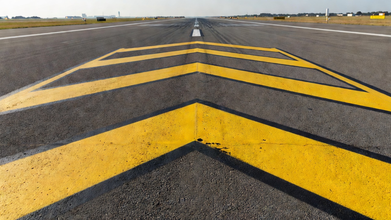
The visual identification of a stopway is achieved through specific markings defined by ICAO Annex 14, Section 7.3, Pre-threshold area marking. These markings consist of yellow chevrons painted on the stopway surface, pointing in the direction of the runway. The chevron marking system is a recommended practice per ICAO.
ICAO Annex 14, Section 7.3.1 specifies: When the surface before a threshold is paved and exceeds 60 meters in length and is not suitable for normal use by aircraft, the entire length before the threshold should be marked with a chevron marking.
ICAO Annex 14, Section 7.3.2 specifies: A chevron marking should point in the direction of the runway and be placed as shown in Figure 7-2.
ICAO Annex 14, Section 7.3.3 specifies: A chevron marking should be of conspicuous colour and contrast with the colour used for runway markings, it should preferably be yellow. It should have an overall width of at least 0.9 metres.
The chevron marking specifications in detail:
- Color: Yellow, chosen because it provides high contrast with the white markings used on runways (centerline, threshold markings, touchdown zone markings, runway designation markings).
- Direction: Chevrons point toward the runway, indicating that the stopway is before the threshold and the usable runway lies ahead.
- Width: Each chevron stripe must be at least 0.9 meters wide.
- Angle: Chevrons are oriented at approximately 45 degrees to the centerline.
- Arrangement: Chevrons are arranged in an array pattern across the entire width of the stopway, with individual chevrons spaced across the pavement.
The operational significance of these markings cannot be overstated. The yellow chevrons serve as a visual barrier indicating that the surface area is not suitable for takeoff, landing, or taxiing under normal operating conditions. Pilots must not use the stopway for landing roll, takeoff ground roll, or routine taxiing. The stopway may only be used for emergency deceleration during a rejected takeoff.
In addition to surface markings, ICAO Annex 14, Section 5.5.3 provides specifications for stopway edge markers:
- Section 5.5.3.1 (Recommendation): Stopway edge markers should be provided when the extent of a stopway is not clearly indicated by its appearance compared with that of the surrounding ground.
- Section 5.5.3.2 (Standard): Stopway edge markers shall be sufficiently different from any runway edge markers used to ensure that the two types of markers cannot be confused.
The note accompanying Section 5.5.3.2 states that markers consisting of small vertical boards camouflaged on the reverse side, as viewed from the runway, have proved operationally acceptable. This design ensures that when viewed from the runway, the markers are visible and distinguishable from runway edge markers, but when viewed from the opposite direction (the stopway side), they are less visually prominent.
For night operations, ICAO Annex 14, Section 5.3.16 requires stopway lights for a stopway intended for use at night. These lights must be provided and must be clearly distinguishable from runway edge lights to prevent pilots from confusing the stopway with the runway during visual approaches.
Stopway Bearing Capacity
The bearing capacity of a stopway is one of its most critical engineering attributes, directly tied to its functional purpose. ICAO Annex 14, Section 3.7.3 establishes a recommended practice: A stopway should be prepared or constructed so as to be capable, in the event of an abandoned take-off, of supporting the aeroplane which the stopway is intended to serve without inducing structural damage to the aeroplane.
The bearing capacity requirement means that the stopway pavement structure must be engineered to withstand the static and dynamic loads imposed by the critical aircraft during a rejected takeoff. During a rejected takeoff at high speed, the aircraft applies significant vertical loads through the landing gear, as well as longitudinal braking forces that induce shear stresses within the pavement structure. The stopway pavement must resist these forces without:
- Structural collapse, The pavement must not rupture or sink under the aircraft weight.
- Surface disintegration, Spalling, raveling, or aggregate loss that could cause FOD damage to aircraft engines or control surfaces must not occur.
- Irregular surface deformation, Rutting or differential settlement that could cause directional control difficulties or structural overload during high-speed braking must be prevented.
- Water-induced weakening, The pavement structure must be adequately drained to prevent water accumulation that could reduce subgrade bearing capacity.
The stopway bearing strength may be reported using the Pavement Classification Number (PCN) system, which is the ICAO-standard method for reporting pavement bearing strength. The PCN is compared to the Aircraft Classification Rating (ACR) to determine whether the pavement can support the aircraft. For unrestricted operations, the ACR should be less than or equal to the PCN. However, it is important to note that the stopway is not required to achieve the same PCN as the runway, since it is only used in emergency conditions rather than for regular operations. The key requirement is that the stopway supports the aircraft without inducing structural damage, not that it supports unlimited repeated loading.
The subgrade beneath the stopway must also meet stability requirements. Poor subgrade conditions can lead to differential settlement, which creates surface irregularities that could cause aircraft damage during a high-speed rejected takeoff. Proper geotechnical investigation, compaction, and drainage are essential during stopway construction. The use of stabilized subgrade layers or geotextile reinforcement may be necessary in areas with weak native soils.
The surface friction characteristics requirement (ICAO Annex 14, Section 3.7.4, Standard) is closely related to bearing capacity. The stopway surface must provide friction characteristics at or above those of the associated runway. If the runway has been grooved or scored to enhance friction, the stopway should receive similar surface treatment. Friction testing using continuous friction measuring devices (such as the Saab Friction Tester, Griptester, or Mu-Meter) should be conducted periodically to verify compliance.
Stopway Inspection
Comprehensive stopway inspection is an integral component of runway safety management. Inspections must cover surface condition, markings, obstructions, drainage, and lighting systems. The inspection framework follows the same principles established for runway inspections under national regulations such as FAA Part 139 (Certification of Airports) and the general aerodrome maintenance requirements of ICAO Annex 14, Chapter 10.
Surface Condition Inspection
The stopway surface condition inspection must evaluate:
- Friction characteristics: Measured using continuous friction measuring devices (CFMDs) to ensure the stopway meets the ICAO standard of friction at or above the associated runway level. Friction testing should be conducted at the same intervals as the associated runway, with results recorded and trended over time.
- Pavement distress: Cracks, spalling, raveling, fretting, and rutting must be documented. Significant distress reduces braking effectiveness and can generate FOD.
- Surface irregularities: Steps, depressions, or bumps that could induce structural damage to aircraft during emergency braking must be identified and corrected. Surface profile measurements using a 3-meter straightedge should not exceed tolerances defined in national standards.
- FOD control: Regular sweeping and debris removal is essential. Loose aggregate, pavement fragments, rubber deposits, and any foreign objects must be removed promptly.
- Grooving/scoring condition: If the stopway has been grooved or scored, the groove depth, width, and spacing must be maintained within design tolerances.
Obstructions Inspection
The stopway must remain clear of objects that could cause damage to an aircraft during an emergency stop:
- Frangibility requirements: Any lighting fixtures, signs, or markers located on or adjacent to the stopway must be frangible, designed to break away on impact without causing structural damage to the aircraft.
- Obstacle limitation surfaces: The stopway lies within the runway obstacle limitation surfaces. Objects penetrating these surfaces must be removed or marked.
- Temporary obstructions: Construction equipment, vehicles, or materials must not be placed on the stopway.
Drainage Inspection
Proper drainage is critical to stopway functionality:
- Transverse slopes must be maintained within design tolerances (1.5% for Code C-F, 2% for Code A-B, minimum 1%) to ensure rapid water runoff.
- Standing water or ponding indicates inadequate drainage and creates hydroplaning risks during emergency braking.
- Drainage systems such as ditches, culverts, and subsurface drains must be functional and free of blockages.
- Erosion of shoulders or adjacent areas must be identified and repaired before it undermines the stopway pavement structure.
Markings and Lighting Inspection
- Yellow chevron markings must be visible and not faded. Chevron stripe width must be at least 0.9 meters. Repainting is required when reflectivity or contrast diminishes.
- Stopway edge markers (if provided) must be in place and clearly distinguishable from runway edge markers.
- Stopway lights (for night operations) must be operational, with correct intensity and alignment. Light fixtures must be frangible.
Inspection Frequency
Per FAA Part 139 and ICAO recommended practices, stopway inspection frequencies follow the runway inspection schedule:
| Inspection Type | Frequency | Scope |
|---|---|---|
| Daily | Once per day during operational hours | Visual inspection for FOD, surface condition, marking visibility, obstructions |
| Periodic | Quarterly or as determined by traffic volume | Friction measurement, pavement condition assessment |
| Annual | Once per year | Full condition evaluation, including drainage systems, lighting, marking reflectivity, pavement structural assessment |
| Post-event | After any rejected takeoff or overrun incident | Immediate inspection for damage assessment |
Stopway and Runway Safety
The stopway contributes directly to runway safety by extending the distance available for a rejected takeoff. Rejected takeoffs are among the most safety-critical events in aviation. A rejected takeoff at high speed, particularly above 80 knots, places extreme demands on the aircraft braking system, tire-ground interface, and pilot reaction time. If the available accelerate-stop distance is insufficient, the aircraft will overrun the runway end, potentially with catastrophic consequences.
The relationship between stopway length and runway safety can be quantified through the balanced field length concept. In aircraft performance engineering, the balanced field length is the distance at which the accelerate-stop distance equals the takeoff distance (including the airborne segment to clear a 35-foot or 50-foot obstacle). For runways with limited length, a stopway effectively increases the accelerate-stop distance, shifting the balanced field length calculation and allowing higher takeoff weights or providing greater safety margins.
Overrun events at airports without adequate stopways or RESA have been a significant focus of aviation safety investigations. The National Transportation Safety Board (NTSB) and the European Aviation Safety Agency (EASA) have both issued recommendations regarding runway end safety areas and stopway provision. The installation or extension of stopways has been identified as a cost-effective safety enhancement at airports where full RESA dimensions cannot be achieved due to physical constraints.
The Flight Safety Foundation’s Approach-and-Landing Accident Reduction (ALAR) toolkit identifies runway overrun during rejected takeoff as a high-risk event. The availability of an adequate stopway or ASDA directly mitigates this risk. Airlines, airports, and regulators use the ASDA value to ensure that aircraft operating on a given runway have sufficient accelerate-stop distance for all anticipated takeoff weights, runway conditions, and environmental temperatures.
ICAO Annex 14 Requirements
ICAO Annex 14, Volume I, Aerodromes (8th Edition, July 2018, incorporating all amendments up to Amendment 14-A) contains the complete set of international Standards and Recommended Practices (SARPs) for stopways. The relevant sections are:
Section 3.7, Stopways
| Paragraph | Type | Requirement |
|---|---|---|
| 3.7 | Note | The inclusion of detailed specifications for stopways is not intended to imply that a stopway has to be provided. Guidance on the use of stopways is found in Attachment A, Section 2. |
| 3.7.1 | Standard | A stopway shall have the same width as the runway with which it is associated. |
| 3.7.2 | Recommended Practice | Slopes and changes in slope on a stopway, and the transition from a runway to a stopway, should comply with the specifications for the runway, except that the 0.8% limitation for the first and last quarter need not apply, and at the junction the maximum rate of slope change may be 0.3% per 30m for Code 3 or 4. |
| 3.7.3 | Recommended Practice | A stopway should be prepared or constructed to support the aeroplane during an abandoned take-off without inducing structural damage. |
| 3.7.4 | Standard | The surface of a paved stopway shall be constructed to provide surface friction characteristics at or above those of the associated runway. |
Section 5.3.16, Stopway Lights
Stopway lights shall be provided for a stopway intended for use at night. These lights must be distinguishable from runway edge lights.
Section 5.5.3, Stopway Edge Markers
Stopway edge markers should be provided when the extent of the stopway is not clearly indicated by its appearance. They shall be sufficiently different from runway edge markers to prevent confusion.
Section 7.3, Pre-Threshold Area Marking
When the surface before a threshold is paved and exceeds 60 meters in length and is not suitable for normal use by aircraft, the entire length should be marked with yellow chevrons pointing toward the runway, with each chevron stripe at least 0.9 meters wide.
Chapter 10, Aerodrome Maintenance
The general maintenance requirements of Chapter 10 apply to stopways. Pavements must be maintained in a condition not less than when constructed (Section 10.2). Contaminants must be removed (Section 10.3). Visual aids must be maintained (Section 10.5).
Stopway Maintenance
The maintenance of a stopway follows the same principles as runway pavement maintenance, with specific emphasis on friction characteristics and structural integrity. The key maintenance activities are:
Pavement Maintenance
- Surface friction restoration: When friction measurements fall below the associated runway level, remedial action is required. This may include rubber removal, grooving, or overlay. ICAO Annex 14, Section 3.1.26 specifies that the surface texture depth for new surfaces should be not less than 1.0 mm.
- Crack sealing: Cracks in the stopway pavement must be sealed to prevent water infiltration, which weakens the subgrade and accelerates pavement deterioration through freeze-thaw cycles.
- Spall repair: Areas of spalled or raveled pavement must be repaired to prevent FOD generation and surface deterioration.
- Overlay: When the existing pavement surface has deteriorated beyond the point where restoration is cost-effective, an asphalt or concrete overlay may be applied.
Markings Maintenance
- Yellow chevron repainting: Chevron markings should be repainted when they fade to the point where contrast with the pavement surface is diminished. The minimum chevron stripe width of 0.9 meters must be maintained.
- Edge marker replacement: Worn or damaged stopway edge markers must be replaced promptly.
- Stopway light replacement: Burned-out or damaged light units must be replaced to maintain night operational capability.
Drainage Maintenance
- Transverse slope verification: Annual surveys should confirm that the transverse slopes remain within design tolerances.
- Drainage system cleaning: Ditches, culverts, and subsurface drains should be cleaned to remove sediment and vegetation buildup.
- Standing water correction: Areas where water ponds on the stopway surface must be corrected through surface regrading or improved drainage.
FOD Control
- Regular sweeping: The stopway should be swept at the same frequency as the runway to remove debris.
- Post-storm inspection: After high winds or storms, the stopway must be inspected for debris blown onto the surface.
- Edge maintenance: Vegetation control along the stopway edges prevents plant growth from encroaching onto the pavement and reduces wildlife attractants.
Record Keeping
All inspection findings, maintenance actions, friction measurement results, and bearing capacity assessments should be documented and maintained as part of the aerodrome’s safety management system records. This documentation supports regulatory compliance demonstrations and provides trend data for predictive maintenance planning.
Regulatory Compliance
Failure to maintain a stopway to ICAO Annex 14 standards can result in the stopway being declassified, meaning it can no longer be counted in the ASDA calculation. If this occurs, the declared distances must be revised and published via NOTAM, and the ASDA will decrease to equal the TORA. This reduction in declared distances can significantly impact aircraft operations, potentially reducing maximum takeoff weights or restricting certain aircraft types from using the runway.
Conclusion
The stopway is a specialized aviation infrastructure element that serves a single critical function: providing a safe deceleration surface for aircraft during rejected takeoffs. As part of the declared distances system, the stopway directly extends the Accelerate-Stop Distance Available (ASDA), enabling airports to accommodate heavier aircraft operations and providing essential safety margins for one of the most demanding flight maneuvers. The regulatory framework established by ICAO Annex 14, governing stopway width, slope, bearing capacity, markings, and lighting, ensures that stopways meet the rigorous performance standards required for their emergency role. Proper inspection, maintenance, and record keeping are essential to preserve stopway functionality and compliance. For airport operators, aerodrome certification authorities, and flight operations planners, understanding stopway specifications and limitations is fundamental to runway safety management.
For further information, consult ICAO Annex 14, Volume I, Aerodromes (latest edition), FAA Advisory Circular AC 150/5300-13B, Airport Design, and the relevant national civil aviation authority regulations. Periodic review of declared distances and stopway condition as part of the aerodrome’s safety management system is recommended.
Frequently Asked Questions
- What is the primary purpose of a stopway?
- A stopway provides a prepared surface beyond the runway end to safely decelerate an aircraft during an aborted or rejected takeoff. It is designed to support the aircraft without inducing structural damage and is incorporated into the Accelerate-Stop Distance Available (ASDA) calculation for the runway.
- How does a stopway differ from a clearway?
- A stopway is a paved area designed to support aircraft during ground roll in a rejected takeoff, and it is included in ASDA. A clearway, by contrast, is an obstacle-free area for the airborne phase of takeoff, included only in TODA. Aircraft must be airborne before entering a clearway, they cannot use it for ground deceleration.
- What markings identify a stopway?
- Stopways are marked with yellow chevrons pointing toward the runway, as specified by ICAO Annex 14 Section 7.3. Each chevron stripe must be at least 0.9 meters wide. The chevrons indicate that the area is not suitable for normal takeoff, landing, or taxiing operations, only for emergency use during aborted takeoffs.
- What are the bearing capacity requirements for a stopway?
- ICAO Annex 14 Section 3.7.3 recommends that a stopway should be constructed to support the aircraft it serves during an abandoned takeoff without inducing structural damage. The surface friction characteristics of a paved stopway must be at or above those of the associated runway per ICAO Annex 14 Section 3.7.4.
- How is ASDA calculated with a stopway?
- ASDA (Accelerate-Stop Distance Available) is calculated as TORA (Takeoff Run Available) plus the length of the stopway. For example, if a runway has a TORA of 2,500 meters and a stopway of 300 meters, the ASDA is 2,800 meters. The stopway only affects ASDA, not TORA, TODA, or LDA.
- What is the required width of a stopway?
- ICAO Annex 14 Section 3.7.1 states that a stopway shall have the same width as the runway with which it is associated. This is a standard (mandatory) requirement, not merely a recommendation.
- How often should stopways be inspected?
- Stopways should undergo daily visual inspections for FOD, surface condition, and marking visibility. Periodic friction measurements and pavement condition assessments are also required. Annual full condition evaluations including drainage, lighting, and marking checks are recommended per FAA Part 139 and ICAO practices.
- What is the difference between a stopway and a RESA?
- A stopway is a prepared paved area designed to support aircraft during rejected takeoffs, included in ASDA. A Runway End Safety Area (RESA) is a graded, obstacle-free zone beyond the runway strip designed to mitigate damage during overruns or undershoots. RESA is not included in any declared distance calculation.
This is a reference entry. TarmacView provides drone inspection services and doesn't sell the equipment or materials described in this glossary.