The subbase is an optional granular or stabilized layer placed between the subgrade and base course, providing additional load distribution, drainage, frost protection, and a working platform during construction. In airport pavements, subbase thickness is often substantial to handle heavy loads. Covers subbase materials, functions, and inspection indicators of subbase problems.
Subbase Course in Pavement Structures – Definition, Functions, Materials, and Design
Definition of Subbase Course
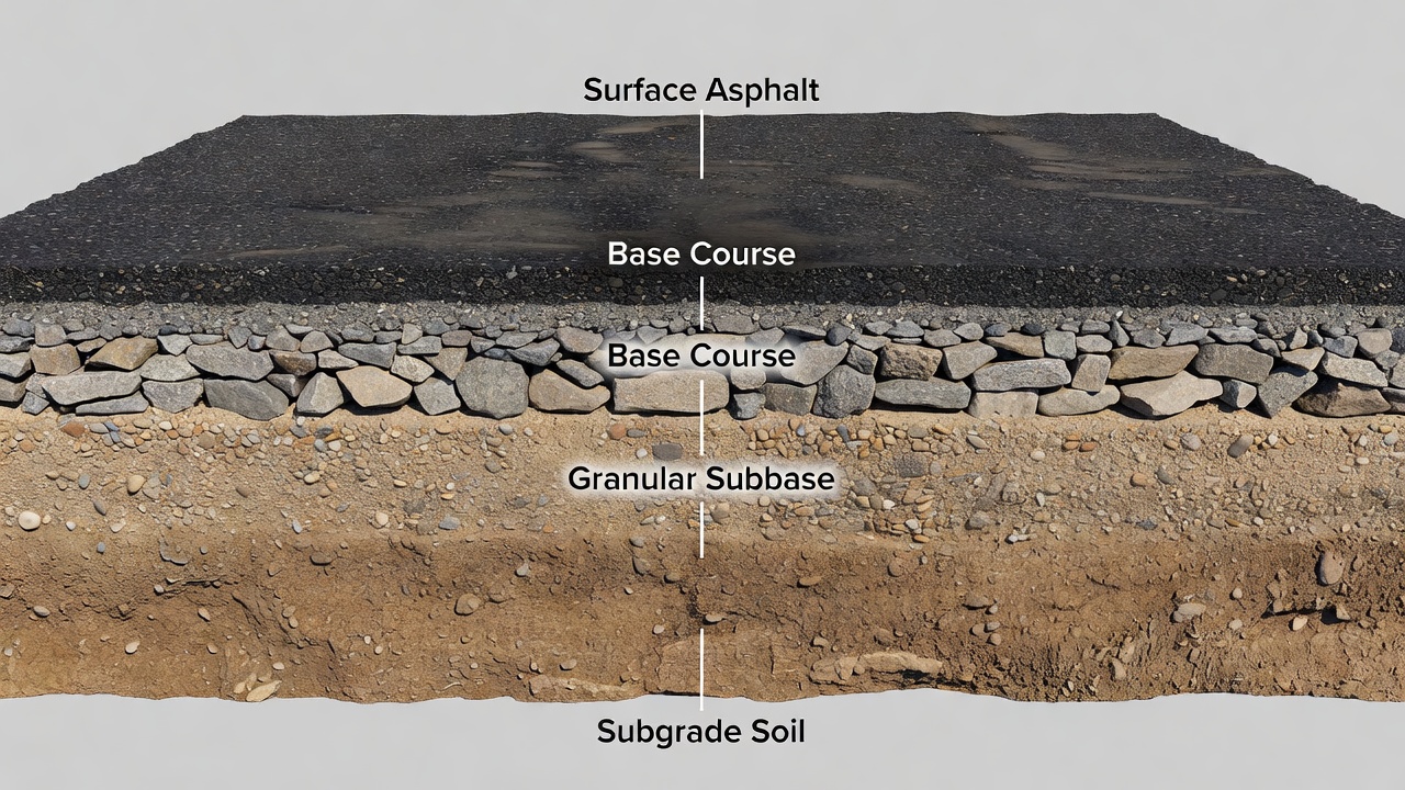
The subbase course is a structural layer in pavement systems situated between the subgrade (the naturally occurring or prepared soil foundation) and the base course. In the traditional pavement layer hierarchy from bottom to top, the sequence consists of subgrade, subbase (optional), base course, and surface course (either asphalt concrete or Portland cement concrete). The subbase functions as a load-spreading medium, a drainage layer, a frost barrier, and a construction platform. According to FAA Advisory Circular AC 150/5320-6G, Airport Pavement Design and Evaluation, the subbase is defined as the layer of specified material of designated thickness placed on a subgrade to support a base course and surface course. The ICAO Aerodrome Design Manual (Doc 9157, Part 3 — Pavements) similarly defines the subbase as the layer that provides additional load distribution and contributes to the drainage and frost resistance of the pavement structure.
The subbase is an optional layer in pavement design — it is incorporated when structural, drainage, or environmental conditions warrant its inclusion. In many highway pavements, the subbase may be omitted when subgrade conditions are excellent and traffic loads are light. However, in airport pavements, where wheel loads routinely exceed 100,000 pounds per tire for large commercial aircraft (Boeing 777 main gear tire loads approach 60,000 pounds), the subbase is almost always required and often constitutes a substantial portion of the total pavement thickness. FAA minimum subbase thickness for light-load pavements (less than 60,000 pounds gross aircraft weight) is 6 inches, and for heavy-load pavements the subbase can exceed 24 inches. The subbase is not merely a filler layer — it is an engineered component with specific material properties, compaction requirements, and thickness design criteria that directly influence pavement performance and service life.
Functions of the Subbase Course
The subbase serves five primary functions in a pavement structure, each critical to long-term performance.
Load Distribution. The fundamental structural purpose of the subbase is to reduce the vertical compressive stress transmitted to the subgrade to a level that the subgrade can sustain without excessive deformation. Aircraft loads applied at the surface generate stress bulbs that propagate downward through the pavement structure. The base course reduces stress to an intermediate level, and the subbase further reduces stress before it reaches the subgrade. The stress reduction follows Boussinesq’s theory of stress distribution in elastic layers, modified for layered pavement systems. A pavement structure without a subbase would transfer higher stresses to the subgrade, potentially causing subgrade shear failure, excessive rutting, or consolidation settlement. The subbase thickness is determined by the required stress reduction factor, which depends on the subgrade California Bearing Ratio (CBR), the design aircraft loads, and the number of load applications over the design life.
Drainage. Water that infiltrates through the surface course or enters from the sides of the pavement must be removed to prevent deterioration. The subbase, when constructed of free-draining granular material, acts as a drainage blanket that captures water and conveys it laterally to edge drains or ditches. The drainage function is particularly critical in airport pavements where large areas of impermeable surface (runways, taxiways, and aprons) shed substantial quantities of rainfall. Subbase materials used for drainage must have high hydraulic conductivity (permeability typically greater than 1,000 feet per day) and must be protected from clogging by fines from the subgrade below or the base above. The FAA requires that when a subbase serves as a drainage layer, it must extend laterally beyond the pavement edge and connect to an open ditch or subsurface drain system.
Frost Protection. In seasonal frost areas, the subbase protects the pavement structure from frost heave and thaw weakening. Frost heave occurs when water accumulates and freezes in the subgrade, forming ice lenses that displace the pavement upward. The subbase, constructed of non-frost-susceptible materials, limits the depth of frost penetration into the subgrade. Per the Corps of Engineers design method (UFC 3-250-01FA), the combined thickness of pavement surface, base, and subbase must be sufficient to either limit subgrade frost penetration to acceptable amounts (Limited Subgrade Frost Penetration Method) or to provide adequate structural capacity during the thaw-weakened period (Reduced Subgrade Strength Method). Subbase materials for frost protection must contain less than 3% passing the No. 200 (75 μm) sieve and must not be frost-susceptible per standardized classification systems.
Construction Platform. The subbase provides a stable working platform for construction operations. During pavement construction, the subgrade surface may be soft, wet, or irregular, making it difficult for construction equipment to operate efficiently. A subbase layer of compacted granular material creates a firm, all-weather surface that supports haul trucks, pavers, rollers, and other equipment. This function is especially valuable when construction must proceed during wet weather or over weak subgrades. The construction platform function is recognized in the FAA AC 150/5320-6G as a practical reason for maintaining a minimum 6-inch subbase even when structural analysis would permit a thinner section.
Filtration and Separation. The subbase prevents the migration of fine-grained subgrade soils into the coarser base course above. Without a properly graded subbase, subgrade fines (silt and clay particles) can be pumped upward into the base under repeated traffic loading, a phenomenon known as pumping. This migration degrades the structural capacity of the base and can lead to surface cracking and pavement failure. The subbase acts as a filter, with a gradation designed to retain subgrade particles while allowing water to pass. The filter criteria, based on the work of Terzaghi and subsequent research, specify the relationship between particle sizes of the subbase and the subgrade to prevent migration while maintaining permeability.
When a Subbase is Required
The subbase is not always required in pavement design, but specific conditions necessitate its inclusion. Per FAA AC 150/5320-6G, the primary criteria for subbase requirement are:
Structural Thickness Criteria. If the pavement structural design indicates a subbase thickness less than 6 inches (150 mm), the subbase may be eliminated, provided that the base course can be placed directly on the prepared subgrade. This 6-inch threshold is based on practical construction considerations — it is the minimum compacted thickness that can be placed and compacted uniformly using conventional construction equipment. When the design requires more than 6 inches of subbase, the full computed thickness must be provided. In FAARFIELD (FAA’s layered elastic pavement design software), the program automatically computes the required subbase thickness based on the structural analysis. The software uses layered elastic theory to compute stresses and strains at critical locations within the pavement structure and iteratively adjusts layer thicknesses to meet fatigue and deformation criteria.
Subgrade Strength Criteria. A subbase is required when the subgrade CBR is less than 5 for flexible pavements or when the modulus of subgrade reaction (k-value) is less than 100 psi/inch for rigid pavements. Weak subgrades cannot support the base course and surface layer directly without excessive deformation. The subbase spreads the load over a larger area of the subgrade, reducing stress to tolerable levels. The relationship between subgrade CBR and required subbase thickness is nonlinear — weaker subgrades require disproportionately thicker subbase layers. For example, a subgrade with CBR of 3 may require twice the subbase thickness of a subgrade with CBR of 6 for the same aircraft loading.
Drainage Requirements. When the pavement is located in an area of high rainfall or when the water table is close to the subgrade elevation, a drainage layer is necessary. The subbase, when constructed of permeable material, serves this function. The time to drain criterion in pavement design specifies that water should be removed from the pavement structure within a specified period (typically 50% drainage within 10 days for airport pavements). The subbase permeability and thickness are selected to achieve this drainage requirement.
Frost Protection Requirements. In regions where the design freezing index exceeds 50 degree-days Fahrenheit, a subbase of non-frost-susceptible material is typically required to prevent frost damage. The required subbase thickness for frost protection is determined using the freezing index, frost-susceptibility classification of the subgrade, and the moisture conditions at the site. In extreme northern climates (Alaska, Canada, Scandinavia), the subbase thickness for frost protection can exceed 48 inches.
Stage Construction Considerations. When pavements are designed for stage construction (initial construction followed by a future overlay), the subbase is often designed for the ultimate traffic loading while the surface and base are designed for initial traffic. This strategy ensures that future strengthening can be accomplished by adding an overlay without major reconstruction of the lower layers.
Subbase Materials
Subbase materials are categorized into three main types: granular unbound materials, stabilized materials, and recycled materials. Each category has specific material properties, construction requirements, and performance characteristics.
Granular Unbound Subbase
Granular unbound subbase consists of crushed stone, gravel, sand, or a blended mixture of these materials, placed and compacted without any cementitious binder. The performance of granular subbase depends on aggregate gradation, particle shape, durability, and compaction density.
Gradation is the most critical property. A well-graded granular subbase contains a range of particle sizes from coarse (up to 3 inches or 75 mm maximum size) to fine (passing the No. 200 sieve), with the fines content typically limited to less than 10% by weight. The gradation must be controlled to achieve maximum density (minimum void ratio) while maintaining sufficient permeability for drainage. Standard gradation specifications for subbase materials are provided in AASHTO M147 (Materials for Aggregate and Soil-Aggregate Subbase, Base, and Surface Courses) and ASTM D2940 (Graded Aggregate Material for Bases or Subbases for Highways or Airports). For airport pavements, the FAA specifies P-154 subbase material in its standard specifications, which requires crushed aggregate with a maximum size of 3 inches and a plasticity index of 6 or less.
Particle shape influences the shear strength and stability of granular subbase. Angular, crushed particles interlock more effectively than rounded particles, providing greater resistance to permanent deformation under repeated loading. The FAA requires that subbase aggregate have at least 50% crushed faces (one or more fractured faces) to ensure adequate particle interlock. Los Angeles Abrasion resistance (ASTM C131) must be less than 50% weight loss, ensuring that particles can withstand construction compaction and traffic loading without degradation.
Durability requirements include soundness testing (ASTM C88) using sodium sulfate or magnesium sulfate, with maximum weight loss of 12% for sodium sulfate or 18% for magnesium sulfate. These tests assess the aggregate’s resistance to weathering and freeze-thaw cycles.
Compaction of granular subbase is typically specified at 95-100% of maximum dry density as determined by the Modified Proctor test (ASTM D1557). Field compaction is achieved using vibratory rollers, with layer thicknesses limited to 6 to 8 inches to ensure uniform density throughout the layer. Moisture content during compaction must be controlled within ±2% of optimum moisture content to achieve target density.
Stabilized Subbase
Stabilized subbase materials incorporate cementitious binders to create a bound layer with enhanced strength, stiffness, and erosion resistance. The three primary types are:
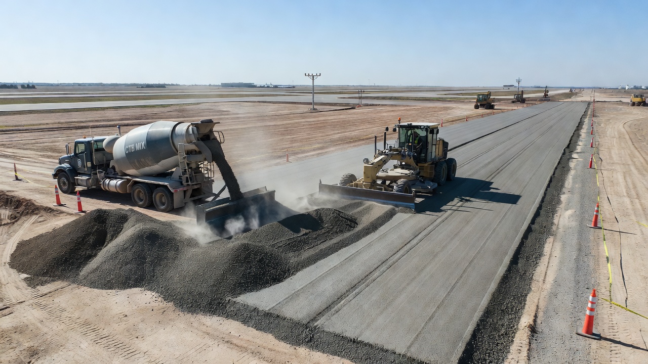
Cement-Treated Subbase (CTB). CTB is a mixture of granular aggregate, Portland cement (typically 3-7% by weight), and water, compacted and cured to form a rigid layer. The primary advantage of CTB over granular subbase is its resistance to erosion and pumping — a significant benefit under concrete pavements where water can accumulate at joints. CTB provides a uniform support for the pavement slab, reducing curling and warping stresses. The American Concrete Pavement Association (ACPA) recommends CTB for high-volume pavements where erosion resistance is critical. Per ACPA EB204P, typical 7-day compressive strength for CTB ranges from 300 to 800 psi (2.1 to 5.5 MPa). CTB is best controlled using compaction density rather than strength, with target density of 95-98% of Modified Proctor maximum. A cement content of 5% is typically sufficient for erosion resistance; higher cement contents (7-8%) produce extremely erosion-resistant layers comparable to lean concrete.
Lean Concrete Subbase (LCB). LCB, also known as econocrete, is a low-strength concrete mixture with 7-12% cement content that produces compressive strengths of 1,000 to 2,000 psi at 28 days. LCB provides the highest level of subbase stiffness and erosion resistance. However, its high stiffness can induce restraint stresses in the overlying concrete pavement slab if the LCB bonds to the slab. To prevent bonding, a bond-breaking medium (typically two spray applications of wax-based curing compound) is applied to the LCB surface before placing the concrete pavement. The ACPA recommends limiting LCB strength to 1,200 psi (8.3 MPa) or less to minimize curling and warping stresses.
Asphalt-Treated Subbase (ATB). ATB is a mixture of aggregate and asphalt binder (typically 3-6% by weight), mixed hot or cold and compacted. ATB provides flexibility combined with improved strength and water resistance compared to granular subbase. It is particularly effective in flexible pavement structures where compatibility with the overlying hot-mix asphalt layers is advantageous. ATB can be placed as a drainage layer when constructed with open-graded aggregate and higher asphalt content. Minimum ATB thickness is typically 2 inches (50 mm).
Recycled Materials in Subbase
The use of recycled materials in subbase construction has increased substantially due to economic and environmental benefits. The FAA AC 150/5320-6G encourages the use of recycled materials in pavement construction, subject to meeting material property requirements.
Reclaimed Asphalt Pavement (RAP). RAP is processed from milled or crushed existing asphalt pavements. When used in granular subbase, RAP behaves similarly to virgin aggregate, though with lower unit weight and higher asphalt content that can affect compaction characteristics. Research indicates that RAP blends with up to 50% RAP content can meet subbase material specifications, though the asphalt coating on RAP particles can reduce the friction angle and shear strength compared to virgin aggregate. RAP is most effectively used in stabilized subbase (CTB or ATB) where the binder compensates for the reduced particle interlock.
Recycled Concrete Aggregate (RCA). RCA is crushed concrete from demolished pavements and structures. It has excellent load-bearing characteristics due to the residual cement paste that can provide some cementitious activity. RCA typically has higher water absorption than virgin aggregate (4-8% versus 1-3%) and may contain reinforcing steel that must be removed during processing. Studies by the Federal Highway Administration (FHWA) have demonstrated that RCA performs satisfactorily in granular subbase applications when properly processed and graded.
Industrial Byproducts.Blast furnace slag, steel slag, and fly ash have been successfully used in subbase construction. Blast furnace slag (both air-cooled and granulated) provides excellent load-bearing capacity and can be used in granular or stabilized subbase. Fly ash, particularly self-cementing Class C fly ash, can be used as a stand-alone stabilizer for subbase materials, with the American Coal Ash Association providing guidelines for fly ash content (typically 10-20% by weight).
Drainage and Frost Protection Role
The subbase serves as the primary drainage conduit and frost protection layer within the pavement structure. These roles are often the determining factors in subbase thickness design.
Subsurface Drainage Mechanism. Water enters the pavement structure through cracks in the surface, along pavement edges, and from the underlying subgrade (particularly when the water table is high). Without effective drainage, this water saturates the pavement layers, reducing the strength of both granular materials and subgrade soils. The subbase, constructed of permeable material (typically with permeability exceeding 1,000 ft/day), captures this water and conveys it laterally to edge drains or outfalls. The drainage design follows Darcy’s Law for flow through porous media, with the drainage capacity determined by the subbase thickness, permeability, and the hydraulic gradient (pavement cross-slope plus longitudinal grade).
Per the FAA AC 150/5320-6G, when a drainage layer is required, it must meet these criteria: (1) permeability of at least 1,000 ft/day; (2) thickness of at least 4 inches; (3) extension to an open ditch or connection to subsurface drains; (4) gradation that meets filter criteria relative to adjacent materials. The drainage layer reduces the time to drain — a critical parameter in pavement design — from potentially months (for a poorly draining structure) to days or hours.
Frost Protection Design Methods. Two principal methods are used for frost design of pavements:
Limited Subgrade Frost Penetration Method. This method aims to limit the depth of frost penetration into the frost-susceptible subgrade to an acceptable amount. The required combined thickness of pavement surface, base, and subbase is determined using the modified Berggren formula for frost penetration, which accounts for air freezing index, thermal properties of pavement materials, and moisture content. The design freezing index is typically taken as the average of the three coldest winters in the most recent 30 years. For example, in a location with a design freezing index of 1,000 degree-days Fahrenheit and a subgrade frost group classification of F3, the required combined thickness might be 36 to 48 inches. This method is most economical in regions with low to moderate freezing indices.
Reduced Subgrade Strength Method. This method acknowledges that some frost penetration will occur into the subgrade but ensures the pavement has adequate structural capacity during the thaw-weakened period in spring. The subgrade’s effective strength during thaw is reduced to a fraction of its normal strength (by as much as 50-70% for frost-susceptible soils), and the pavement is designed to accommodate the reduced support. The subbase thickness in this method is often less than that required for limited frost penetration, making it more economical in cold regions. For pavement design using this method, the Corps of Engineers provides frost-area soil support indexes (Table 3 of UFC 3-250-01FA) that replace the normal CBR values in thickness design.
Non-Frost-Susceptible Subbase Materials. For frost protection, subbase materials must be non-frost-susceptible (NFS) per standardized classification. The Corps of Engineers classification defines NFS materials as those containing less than 3% by weight of particles finer than 0.02 mm (classified as S1 and S2 materials). These materials do not experience significant ice segregation and maintain their strength during freezing and thawing. In practice, this requires screening and washing of aggregate to remove excess fines, and careful quality control during construction to ensure fines content does not exceed specification limits.
Subbase Compaction
Proper compaction of the subbase is essential for achieving the required density, strength, and stiffness. Inadequate compaction leads to post-construction settlement, loss of support, and premature pavement failure.
Compaction Specifications. Subbase compaction is specified as a percentage of the maximum dry density determined by laboratory compaction tests. The Modified Proctor test (ASTM D1557 / AASHTO T180) is the standard for subbase materials, applying a 10-lb hammer falling 18 inches in five layers, producing a compactive effort of 56,000 ft-lb/ft³. The FAA requires compaction of subbase to 95-100% of Modified Proctor maximum dry density for airport pavements. Roadway specifications (AASHTO) typically require 95% for subbase. The moisture content at compaction must be within ±2% of optimum moisture content to achieve target density. Moisture control is critical: too dry, and the material will not achieve adequate density; too wet, and pore pressures develop that prevent compaction and may lead to instability.
Lift Thickness. The subbase is placed in lifts (layers) of uniform thickness to ensure uniform compaction throughout the layer depth. Maximum lift thickness depends on the compaction equipment: for heavy vibratory rollers (10-12 ton static weight), lifts up to 8 inches (200 mm) can be effectively compacted; for lighter equipment, lifts are limited to 4-6 inches (100-150 mm). The minimum lift thickness is typically 3 inches (75 mm) to ensure uniform material distribution and compaction. The subbase is often placed in multiple lifts for thick sections (airport subbases commonly exceed 12 inches and may reach 24-36 inches).
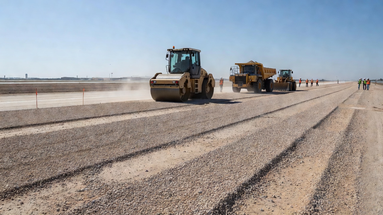
Compaction Equipment.Vibratory smooth-drum rollers are the most effective equipment for compacting granular subbase materials. The vibration frequency (typically 1,500-3,000 vibrations per minute) and amplitude (0.02-0.08 inches) are selected based on the material type and lift thickness. The roller operates at speeds of 2-4 mph, making 4-6 passes to achieve required density. For stability in thick lifts, pneumatic-tired rollers (rubber-tire rollers with 80-120 psi tire pressure) may follow the vibratory roller to seal the surface and provide kneading compaction. Vibratory plate compactors are used in confined areas inaccessible to rollers.
Quality Control Testing. Field density is verified using nuclear density gauges (ASTM D6938) or sand cone tests (ASTM D1556). Testing frequency for airport pavements is typically one test per 2,500 square feet of subbase area per lift. The contractor must achieve the specified density before the next lift or the base course can be placed. If density is not achieved, additional compaction passes are required, with moisture adjustment if necessary. Proof rolling (rolling the completed subbase surface with a heavy loaded vehicle) is also used to identify soft or inadequately compacted areas — if pumping or rutting develops during proof rolling, the affected area must be excavated and recompacted.
Subbase in Airport Pavement Design
Airport pavement design follows specialized methods that account for the unique loading conditions of aircraft — higher wheel loads, larger tire contact areas, multiple-wheel gear configurations, and channelized traffic patterns.
FAA Design Methodology. The FAA design procedure for flexible airport pavements uses layered elastic theory implemented in the FAARFIELD software (FAA’s Rigid and Flexible Iterative Elastic Layer Design). The program models the pavement as a multilayered elastic system with each layer characterized by its resilient modulus (Mr) and Poisson’s ratio. The subbase resilient modulus is determined from the material type and expected performance. For granular subbase, the modulus is stress-dependent and estimated using the relationship:
Mr = k₁θ^(k₂)
where θ is the bulk stress (sum of principal stresses) and k₁, k₂ are material constants. Typical subbase modulus values used in FAARFIELD are:
Material
Resilient Modulus (ksi)
Poisson’s Ratio
Granular subbase
15-30
0.40
Cement-treated subbase
500-1,000
0.20
Lean concrete subbase
1,000-3,000
0.17
Asphalt-treated subbase
100-400
0.35
The program computes vertical strain at the top of the subgrade as the failure criterion for flexible pavements — limiting this strain prevents subgrade rutting. For rigid pavements, FAARFIELD computes edge and corner stresses in the concrete slab, considering the support provided by the subbase and subgrade.
Minimum Thickness Requirements. Per FAA AC 150/5320-6G, Table 3-3 provides minimum layer thicknesses for flexible pavement structures:
Layer
Minimum Thickness
Subbase (non-stabilized)
6 inches (150 mm)
Subbase (stabilized)
6 inches (150 mm)
Base course
4 inches (100 mm)
The 6-inch minimum for subbase is established for practical construction reasons — thinner layers cannot be uniformly placed and compacted. For rigid pavements (Table 3-4), the minimum subbase thickness is also 6 inches.
Typical Airport Subbase Sections. For a Code E airport (designed for aircraft such as the Boeing 777, with wingspan up to 213 feet), a typical flexible pavement section might be:
Surface course: 5 inches of P-401 hot-mix asphalt
Base course: 8 inches of P-209 crushed aggregate base
Subbase: 12 inches of P-154 granular subbase (or 8 inches of P-304 cement-treated subbase)
Subgrade: compacted to 95% density
For a Code C airport (designed for aircraft such as the Boeing 737), a typical section might be:
Surface course: 4 inches of HMA
Base course: 6 inches of crushed aggregate
Subbase: 8 inches of granular subbase
Subgrade: natural or compacted soil
These thicknesses vary substantially based on subgrade CBR, design traffic volume, and climatic conditions. Heavy-load airport pavements (Code F — Airbus A380) may require subbase thicknesses of 18-24 inches.
Modular Ratio and Equivalent Thickness. In FAA design, the structural contribution of the subbase relative to the base course is expressed by the modular ratio or equivalency factor. The FAA method uses structural coefficients that express the relative load-carrying capacity of different materials. When converting a granular subbase to a stabilized subbase, the thickness equivalency factor is approximately 1.5 to 2.0 — meaning 6 inches of CTB can replace 9-12 inches of granular subbase. This equivalency enables designers to optimize pavement sections for cost and material availability.
Subbase in Rigid Airport Pavements. For concrete pavements, the subbase serves additional specific functions. It provides uniform support to prevent slab bridging over soft spots, erosion resistance at joints (where water may collect and pumping can occur under traffic), and a construction platform for placing concrete. The modulus of subgrade reaction (k-value) used in rigid pavement design is affected by the subbase thickness and type. A typical subgrade with k-value of 100 pci can be increased to 150-200 pci with a 6-inch granular subbase, or to 300-600 pci with a 6-inch cement-treated subbase. While the k-value alone has limited effect on required slab thickness (a 50% increase in k-value typically reduces required slab thickness by only 5-10%), the subbase’s erosion resistance and uniformity are critical to long-term performance.
Subbase Failure Indicators
Subbase failure manifests through visible surface distresses that indicate loss of support. Proper identification of these distresses enables targeted repair strategies.
Alligator (Fatigue) Cracking. This is the most common indicator of subbase failure. A series of interconnected cracks forming a pattern resembling alligator skin develops in the wheel paths. According to the Pavement Interactive distress identification guide, alligator cracking is caused by fatigue failure of the hot-mix asphalt surface under repeated traffic loading, typically triggered by loss of base, subbase, or subgrade support from poor drainage. When water accumulates in or beneath the subbase, it causes the underlying materials to weaken, leading to structural failure. The cracking begins as longitudinal wheel-path cracks that progressively connect into the characteristic alligator pattern. Once alligator cracking appears, repair by crack sealing is ineffective — the affected area must be removed and the underlying subbase repaired.
Pumping. Pumping is the ejection of water and fine-grained material (subbase or subgrade soil) through pavement joints and cracks under the action of traffic loads. It is visible as stain deposits on the pavement surface adjacent to joints and cracks. Pumping is a clear indicator of subbase erosion — water accumulating at joints is pressurized by the deflection of the pavement slab under traffic, forcing water and suspended fines outward. The loss of fines creates voids beneath the pavement, leading to loss of support and eventual slab cracking. The ACPA notes that stabilized subbases (CTB, LCB) provide substantially greater erosion resistance than granular subbases, with lean concrete (7-8% cement) classified as “extremely resistant” to erosion.
Rutting. Rutting is the longitudinal surface depression in wheel paths. While often attributed to asphalt mix instability, rutting can also result from subbase consolidation — if the subbase was not adequately compacted during construction, it continues to densify under traffic, causing the overlying layers to settle. The subbase contribution to rutting is identified by digging test pits or taking cores: if the subbase shows reduced thickness with no evidence of lateral movement in the asphalt layer, the rutting is subbase-related.
Depressions. Localized low areas in the pavement surface that collect water after rainfall are called depressions. These are caused by localized subbase settlement, often due to inadequate compaction during construction, subgrade failure beneath the subbase, or subsurface drainage erosion. Depressions are particularly hazardous on airport runways because ponded water can cause hydroplaning during aircraft operations.
Water Bleeding. Visible water seeping through pavement cracks or joints long after rainfall events indicates a saturated subbase — the drainage function of the subbase has been compromised, likely due to clogging of the drainage layer or the edge drainage system. This condition accelerates all other forms of pavement deterioration.
Structural Evaluation Methods. When subbase failure is suspected, nondestructive testing (NDT) is used to evaluate the pavement structure. The Falling Weight Deflectometer (FWD) — standardized per ASTM D4694 — applies an impulse load to the pavement surface and measures the resulting deflection basin. Analysis of deflection data using backcalculation software (e.g., ELMOD, EVERCALC) estimates the modulus of each pavement layer, including the subbase. A subbase modulus significantly lower than the design value indicates deterioration or loss of support. Ground Penetrating Radar (GPR) — per ASTM D6432 — uses electromagnetic pulses to create profiles of the pavement structure, identifying layer thickness variations, moisture accumulation, and voids in the subbase.
Separation and Filtration Geotextiles
Geotextiles are permeable fabrics used in pavement construction to perform separation, filtration, drainage, and reinforcement functions. When used with subbase, geotextiles serve critical roles in maintaining long-term performance.
Separation Function. The primary function of geotextiles in subbase applications is to separate the subbase aggregate from the underlying subgrade soil. Without separation, subgrade fines migrate upward into the subbase under traffic loading (pumping), and subbase aggregate punches downward into the soft subgrade. Both mechanisms degrade the pavement structure. A separation geotextile placed between subgrade and subbase prevents intermixing while allowing water to pass. The FHWA study “Benefits of Using Geotextile Between Subgrade Soil and Base” (ROSAP report DOT 38444) quantified the benefit: geotextile separation reduced subgrade fines migration by 70-90% compared to unreinforced sections.
Filtration Function. The geotextile must be designed as a filter — it must allow water to pass through freely while retaining subgrade soil particles. The filtration criteria for geotextiles are specified in AASHTO M288 (Geotextile Specification for Highway Applications) and ASTM D4751 (Apparent Opening Size). The geotextile’s Apparent Opening Size (AOS) must be smaller than the subgrade particle size to prevent soil migration, while its permittivity (a measure of water flow capacity) must be sufficient to prevent water pressure buildup. Typical AOS values for subgrade separation range from 0.15 to 0.43 mm (US Sieve No. 100 to No. 40).
Drainage Function. In wet conditions, the geotextile can also function as a drainage layer, conveying water laterally within its plane. Geotextile transmissivity (in-plane flow capacity) is specified for this application, typically requiring minimum values of 0.1 to 1.0 ft²/day depending on site conditions. Non-woven geotextiles (needle-punched or heat-bonded) provide higher transmissivity than woven geotextiles.
Reinforcement Function. High-tensile-strength geotextiles (typically woven or geogrids) can provide tensile reinforcement to the subbase, distributing loads over a wider area and reducing subgrade stress. The reinforcement benefit is quantified by the improvement factor — the ratio of the performance of reinforced to unreinforced pavement. Research by Perkins and Ismeik (1997) reported improvement factors of 1.5 to 3.0 for geotextile-reinforced subbase over soft subgrades (CBR less than 3).
Installation Requirements. Geotextiles are placed directly on the prepared subgrade surface, with overlaps of 12-24 inches at seams to prevent separation during subbase placement. The subbase material is placed directly on the geotextile, with construction traffic kept off the exposed geotextile to prevent damage. Minimum subbase cover of 6 inches is recommended before allowing construction equipment on the geotextile.
Geotextile Performance Studies. The National Cooperative Highway Research Program (NCHRP) Report 626 provided comprehensive data on geotextile performance in pavement applications. Key findings: geotextiles can extend pavement life by 2-5 times over soft subgrades (CBR less than 3); performance benefits decrease as subgrade strength increases; and geotextile effectiveness depends on proper installation, with damage during construction being a primary cause of reduced performance.
Subbase and Pavement Performance
The subbase layer, while not visible at the pavement surface, has a direct and quantifiable impact on pavement performance over the design life.
Structural Contribution to Pavement Life. The subbase contributes to pavement structural capacity by distributing loads and reducing critical stresses and strains. In flexible pavement design per the AASHTO Guide, the subbase contributes to the pavement’s Structural Number (SN) through its structural coefficient (a₃) multiplied by its thickness (D₃). The structural coefficient for granular subbase typically ranges from 0.08 to 0.12 per inch, depending on material quality and drainage conditions. A 12-inch subbase with a₃ of 0.10 contributes 1.20 SN units to the total pavement structure. For stabilized subbase, the structural coefficient is higher (0.14-0.28 per inch), meaning less thickness is required for equivalent structural contribution.
Roughness Development. Subbase quality directly affects pavement roughness development. A 2004 study by the Long-Term Pavement Performance (LTPP) program analyzed roughness progression in 500+ pavement sections and found that sections with stabilized subbase developed roughness 30-40% slower than sections with granular subbase, all other factors being equal. The mechanism: stabilized subbase provides more uniform and moisture-resistant support, reducing differential settlement and subgrade intrusion that accelerate roughness.
Moisture Damage Reduction. Pavements with well-designed subbase drainage layers experience 40-60% less moisture-related damage than pavements without drainage, based on LTPP data. The subbase removes water that would otherwise saturate the base course and subgrade, maintaining their structural capacity. The AASHTO Guide incorporates a drainage coefficient (mᵢ) in the structural number calculation, with values ranging from 0.40 (poor drainage) to 1.40 (excellent drainage). A subbase drainage layer providing excellent drainage (m₃ = 1.40) effectively increases the pavement’s structural capacity by 40% compared to poor drainage conditions.
Economic Benefits. While adding a subbase increases initial construction cost, the life-cycle cost of a pavement with a properly designed subbase is typically lower due to reduced maintenance and longer service life. An FHWA study on pavement life-cycle cost analysis found that adding 6 inches of granular subbase to a pavement on CBR 4 subgrade extended pavement life by 8-12 years (from 15 years to 23-27 years) with an incremental cost increase of 15-20%. The benefit-cost ratio for subbase addition ranged from 2:1 to 5:1, depending on traffic volume and material costs.
Future Subbase Innovations. Emerging technologies in subbase design include permeable cement-treated subbase (CTPB) that combines the strength of stabilized material with the drainage capacity of open-graded aggregate; fiber-reinforced subbase incorporating synthetic fibers to increase tensile strength and crack resistance; foamed asphalt stabilized subbase using cold recycling technology for sustainable rehabilitation; and sensor-embedded subbase with embedded instrumentation for real-time monitoring of moisture content, temperature, and structural response throughout the pavement life.
Conclusion. The subbase course is an integral component of airport pavement structures, providing essential load distribution, drainage, frost protection, and construction support functions. Proper subbase design — including material selection, thickness determination, compaction control, and quality assurance — is critical to achieving the 20-30 year design life expected of airport pavements. Understanding subbase behavior and failure modes enables engineers to design more durable pavements and airport operators to identify and address subbase-related distress before it leads to pavement failure. The integration of stabilized materials, recycled aggregates, and geotextile separation continues to advance subbase technology, offering opportunities for more sustainable and cost-effective airport pavement solutions.
Frequently Asked Questions
A subbase course is a structural layer in pavement systems placed between the subgrade (natural soil) and the base course. It provides additional load distribution to reduce stress on the subgrade, facilitates drainage, offers frost protection, and serves as a working platform during construction. In airport pavements, the subbase is often required when the combined structural thickness exceeds practical construction limits for the base course alone.
Subbase materials include granular unbound aggregates (crushed stone, gravel, sand), stabilized materials such as cement-treated subbase (CTB), lean concrete subbase (LCB), asphalt-treated subbase (ATB), and recycled materials like reclaimed asphalt pavement (RAP) and recycled concrete aggregate (RCA). The choice depends on structural requirements, drainage needs, frost protection objectives, and material availability.
Per FAA AC 150/5320-6G, a subbase is required when the structural design indicates a thickness greater than 6 inches (150 mm). It is also required for frost protection in seasonal frost areas, over weak subgrades (CBR less than 5), for drainage provision, and when the combined base and pavement thickness exceeds practical construction lift thicknesses.
The subbase provides frost protection by using non-frost-susceptible granular materials that do not experience significant ice segregation. The combined thickness of pavement, base, and subbase is designed to either limit frost penetration into the subgrade (Limited Subgrade Frost Penetration Method) or to provide adequate structural capacity during the weakened spring thaw period (Reduced Subgrade Strength Method).
Subbase failure indicators include alligator (fatigue) cracking at the pavement surface, pumping (ejection of fine material through joints and cracks), rutting, depressions, and water bleeding through cracks. These distresses typically indicate loss of subbase support, often caused by water infiltration, subbase erosion, or inadequate compaction.
Optimize Your Airport Pavement Design
Ensure your airport pavements meet ICAO and FAA standards for structural integrity, drainage, and frost protection. Our pavement engineering experts can help you design the optimal subbase layer for your airfield.
The base course is a load-distributing layer of high-quality aggregate or stabilized material placed between the subbase (or subgrade) and the asphalt or concre...
The subgrade is the prepared and compacted native soil or improved earth that forms the foundation of a pavement structure. Subgrade strength and uniformity dir...
Airport pavement is the engineered surface for aircraft operations—runways, taxiways, aprons—designed to withstand heavy loads, ensure safety, and support airpo...
5 min read
Airport infrastructure
Engineering
+3
Cookie Consent We use cookies to enhance your browsing experience and analyze our traffic. See our privacy policy.