The subgrade is the prepared and compacted native soil or improved earth that forms the foundation of a pavement structure. Subgrade strength and uniformity directly control pavement performance and design thickness. Covers subgrade evaluation (CBR, resilient modulus), compaction requirements, stabilization methods, and the consequences of subgrade failure (settlement, pumping, differential heave).
Subgrade is the compacted and prepared native soil or improved earth layer that serves as the structural foundation for the entire pavement system. In airport pavement engineering, the subgrade is the single most influential element controlling the required pavement thickness, structural performance, and long-term service life. Every pound of aircraft load transmitted through the pavement structure ultimately must be dissipated into the subgrade without causing excessive deformation or shear failure. The term subgrade originates from the layered pavement concept wherein the “sub” (below) “grade” (finished surface level) identifies the natural or treated soil layer that has been prepared to receive the pavement structure. ICAO Annex 14, Volume I — Aerodrome Design and Operations, specifies that all movement area pavements must rest on a subgrade capable of supporting the intended aircraft loading without excessive deflection or permanent deformation.
Definition and Role in the Pavement System
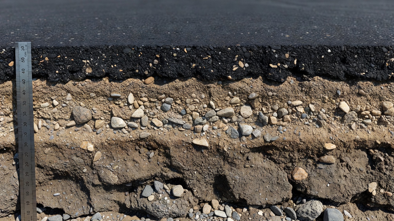
The subgrade is the lowermost structural element of a pavement system, positioned directly beneath the subbase and base courses. In a typical airport pavement cross-section, the layers ascending from bottom to top are: subgrade → subbase course → base course → surface course (either asphalt concrete or Portland cement concrete). The subgrade is not a placed construction material like the layers above it — it is the in-situ soil at the site that has been shaped, compacted, and sometimes chemically or mechanically improved to meet the engineering requirements of the pavement design. The fundamental function of the subgrade is to support the pavement structure without excessive deflection, differential settlement, or shear failure under repeated aircraft loading. It must distribute the stresses imposed by aircraft traffic to a level that the underlying native soil can sustain without distress.
FAA Advisory Circular AC 150/5320-6G, Airport Pavement Design and Evaluation, defines the subgrade as the “naturally occurring soil” that forms one of the four equally important components of the pavement system: (1) the subgrade, (2) the paving materials, (3) the characteristics of applied loads, and (4) climate. The circular explicitly states that “pavement analysis and design involves the interaction of these four components” and that the subgrade must be carefully evaluated during the design phase. The quality of the subgrade directly governs the required thickness of the pavement layers above it — a weak subgrade requires substantially thicker pavement to prevent structural failure, while a strong subgrade permits a thinner, more economical pavement section. This relationship between subgrade strength and pavement thickness is the central principle of pavement thickness design methodology used worldwide.
The role of the subgrade extends beyond pure load support. It must also provide a stable working platform during construction, resist the detrimental effects of moisture changes, withstand freeze-thaw cycles in cold climates, and maintain uniformity across the entire pavement area to prevent differential movements that lead to surface roughness and cracking. The subgrade must be evaluated for its drainage characteristics, shrink-swell potential, and frost susceptibility — all of which influence long-term pavement performance far more than the quality of the surface materials alone.
Subgrade Strength Evaluation
The engineering properties of the subgrade must be quantified through a systematic program of field and laboratory testing. The FAA requires a comprehensive subsurface investigation for all airport pavement projects, including soil borings, sampling, and laboratory testing to characterize the subgrade materials. The two most widely used parameters for subgrade strength evaluation are the California Bearing Ratio (CBR) and the resilient modulus (Mr) , while the modulus of subgrade reaction (k-value) is used specifically for rigid pavement design.
California Bearing Ratio (CBR)
The California Bearing Ratio test, standardized under ASTM D1883, is a penetration test that measures the resistance of compacted soil to penetration by a standard cylindrical plunger at a constant rate of 1.27 mm per minute. The force required to produce penetrations of 2.54 mm and 5.08 mm is compared to the force required to produce the same penetration in a standard crushed limestone material. The CBR value is expressed as a percentage of the standard force — for example, a CBR of 15 means the soil offers 15% of the resistance of the standard crushed stone. The test is performed on soil samples compacted to the density and moisture content specified for construction, and the samples are typically soaked in water for 96 hours before testing to simulate the saturated condition that pavements reach after approximately three years in service.
The FAA specifies that laboratory CBR tests shall be conducted on materials obtained from the site and remolded to the moisture and density required during construction. The soaked CBR condition represents the weakest state of the subgrade, typically occurring during periods of high moisture such as spring thaw or following seasonal storm events. For gravelly materials, CBR tests can yield misleadingly high results due to the confining effects of the test mold, and engineering judgment is required to assign appropriate CBR values. The FAA recommends a maximum subgrade elastic modulus value of 50,000 psi (345 MPa), corresponding to a CBR of approximately 33, for gravel and gravelly soils.
The correlation between CBR and elastic modulus (E) is a fundamental relationship used in pavement design. FAA AC 150/5320-6G provides the equation E (psi) = 1500 × CBR as an approximate relationship adequate for pavement design and analysis. In metric units, this becomes E (MPa) = 10 × CBR. The AASHTO 2002 Design Guide provides an alternative correlation: Mr = 2,555 × CBR^0.64. The number of CBR tests required depends on the variability of the soil conditions encountered — generally, three CBR tests on each major soil type are sufficient, although more tests may be needed where high variability exists.
Resilient Modulus (Mr)
The resilient modulus is a measure of the elastic stiffness of subgrade soils under cyclic loading that simulates the repeated application of aircraft traffic. Unlike the static CBR test, the resilient modulus test (AASHTO T 307) applies a series of repeated load pulses with varying confining pressures and deviator stresses to capture the stress-dependent behavior of granular and fine-grained soils. The resilient modulus is defined as the ratio of the repeated deviator stress to the recoverable (elastic) axial strain: Mr = σd / εr, where σd is the deviator stress and εr is the recoverable strain.
Resilient modulus testing is the primary method for characterizing subgrade materials in mechanistic-empirical pavement design procedures, including the FAA’s FAARFIELD software and the AASHTOWare Pavement ME Design guide. For FAA pavement design, the quality of the subgrade is best characterized by the Elastic Modulus (E) , which is the material parameter used by FAARFIELD in all structural calculations. The resilient modulus values for subgrade soils typically range from approximately 14 to 52 MPa (2,600 to 7,500 psi) depending on the soil type, moisture content, density, and confining pressure. Fine-grained soils exhibit lower resilient modulus values than granular soils, and the modulus decreases significantly as moisture content increases toward saturation.
The FAA recommends that the elastic modulus be estimated from CBR using the 1500 × CBR correlation when laboratory resilient modulus test data is not available. However, for critical projects or where subgrade conditions are highly variable, direct resilient modulus testing is preferred. The dynamic cone penetrometer (DCP), described in FAA Appendix D of AC 150/5320-6G, provides a rapid field-testing alternative that correlates DCP penetration rate to CBR and resilient modulus.
Modulus of Subgrade Reaction (k-value)
For rigid pavement (concrete) design, the subgrade is characterized by the modulus of subgrade reaction (k-value) , measured through a plate bearing test conducted in accordance with AASHTO T 222. The k-value represents the pressure required to produce a unit deflection of the pavement foundation, expressed in units of pounds per cubic inch (pci) or meganewtons per cubic meter (MN/m³). The standard plate diameter for airport pavement testing is 30 inches (762 mm), and the test is performed on test sections constructed to the design compaction and moisture conditions.
The k-value is directly influenced by subgrade soil type, density, and moisture content. Typical k-values range from approximately 50 pci for weak fine-grained subgrades to over 500 pci for strong granular subgrades. When plate bearing test data is not available, the FAA permits estimation of the k-value from CBR data using published correlations. The relationship between elastic modulus E and k-value for design purposes is approximately E (psi) = 20.15 × k^1.284 (k in pci).
Test Parameter
Test Standard
Application
Typical Range
California Bearing Ratio (CBR)
ASTM D1883
Flexible pavement design
2–20 (subgrade)
Resilient Modulus (Mr)
AASHTO T 307
Mechanistic-empirical design
2,600–7,500 psi
Modulus of Subgrade Reaction (k)
AASHTO T 222
Rigid pavement design
50–500 pci
Subgrade Compaction and Moisture Control
Compaction is the mechanical process of densifying soil by reducing the air void content through the application of energy — typically using rollers, vibratory compactors, or impact equipment. The degree of compaction is measured as a percentage of the maximum dry density (MDD) determined in the laboratory through the Modified Proctor test (ASTM D 1557) or Standard Proctor test (ASTM D 698). For airport pavements, the FAA requires compaction to a minimum of 95% of the Modified Proctor maximum dry density for the top 12 inches of subgrade directly beneath the pavement structure, and a minimum of 92% for deeper subgrade layers.
Moisture control during compaction is equally critical. The molding water content during compaction must be maintained within ±2% of the optimum moisture content (OMC) determined by the Modified Proctor test. Soils compacted dry of optimum tend to have higher strength but may experience excessive volume change upon wetting, while soils compacted wet of optimum have lower strength but are less susceptible to moisture-induced volume change. For fine-grained cohesive soils, compaction slightly wet of optimum is often specified to reduce the potential for swelling and to achieve lower permeability.
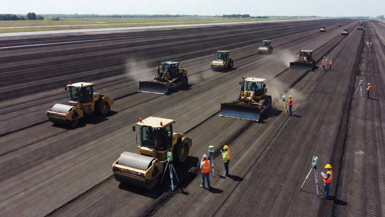
The compaction process for airfield subgrades requires careful selection of equipment and procedures. Sheepsfoot rollers are effective for compacting fine-grained clay soils, vibratory smooth drum rollers work well for granular soils, and pneumatic tire rollers provide kneading action beneficial for both soil types. The lift thickness (the depth of each layer being compacted) is typically limited to 6 to 8 inches for cohesive soils and 8 to 12 inches for granular soils, depending on the compactive effort applied.
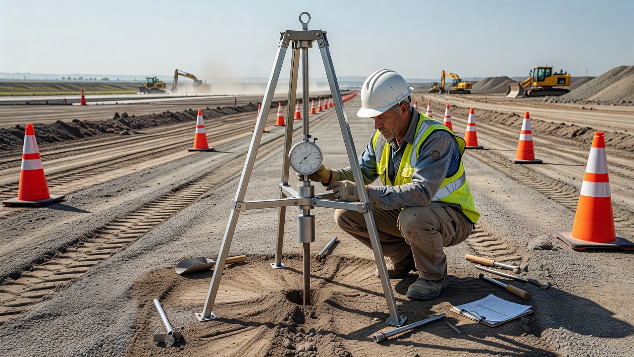
Compaction verification is performed through field density testing using nuclear moisture-density gauges (ASTM D 6938), sand cone tests (ASTM D 1556), or rubber balloon methods (ASTM D 2167). The frequency of testing is specified in the construction quality control plan and typically ranges from one test per 500 to 1,000 square yards of subgrade area. Proof rolling — the process of passing a heavy rubber-tired vehicle over the completed subgrade to identify soft areas — is a traditional but subjective method that remains widely used in airport construction practice.
The consequences of inadequate compaction are severe. Insufficient subgrade compaction leads to post-construction settlement under the repeated dynamic loading of aircraft traffic, resulting in surface depressions, cracking, and roughness. Differential compaction across the pavement area produces uneven support that induces structural cracking in both flexible and rigid pavements. The FAA requires that the engineer’s report document the compaction requirements, testing frequencies, and acceptance criteria for all airport pavement subgrade construction.
Subgrade Stabilization
When the natural subgrade soil lacks the strength, stiffness, or stability required for the intended pavement design, subgrade stabilization is employed to improve its engineering properties. FAA AC 150/5320-6G provides explicit criteria for when stabilization is required: stabilization is recommended when the mean subgrade strength is lower than CBR 5 (elastic modulus approximately 7,500 psi), and is mandatory when the mean subgrade strength is less than CBR 3 (elastic modulus approximately 4,500 psi). Stabilization is also required when any of the following conditions exist: poor drainage, adverse surface drainage, frost conditions, periodic water inundation, or the need to establish a stable working platform for construction equipment.
Chemical Stabilization Methods
Lime stabilization is most effective for plastic clayey soils with plasticity index (PI) greater than 12. Quicklime (calcium oxide) or hydrated lime (calcium hydroxide) reacts chemically with clay minerals through cation exchange, flocculation, and pozzolanic reactions that permanently alter the soil structure. The treatment reduces the plasticity index, increases the optimum moisture content, and permits compaction under wetter conditions. The lime content required to raise the soil pH above 12 identifies the minimum lime needed, typically between 3% and 7% by weight. Long-term strength gains of up to five times the unstabilized strength are achievable with lime treatment.
Cement stabilization works best with coarse-grained soils but can stabilize most soil types. Portland cement hydrates in the presence of soil moisture, forming a cementitious matrix that binds soil particles together. The objectives are to reduce the plasticity index, increase strength, and reduce permeability. Cement is typically added at 3% to 5% by weight for stabilization purposes, with additional cement required if the stabilized layer will serve as a soil cement base course. Caution is required when soluble sulfate content exceeds 3,000 ppm in the soil or mixing water, as sulfate reactions can cause expansive damage. When sulfate content exceeds 5,000 ppm, specific measures must be incorporated to control expansion potential.
Fly ash stabilization utilizes the pozzolanic properties of coal combustion fly ash to stabilize soils, particularly those with low natural cementitious potential. Class C fly ash (high calcium content) has self-cementing properties, while Class F fly ash requires an activator such as lime or cement. The selection of chemical stabilization agent depends on the soil type, project requirements, and economic considerations, as documented in the geotechnical report.
Mechanical Stabilization and Geosynthetics
Geotextiles are permeable fabrics that provide separation between the subgrade and the overlying aggregate layers. Their primary function is to prevent the migration of fine subgrade soil particles into the granular base and subbase layers — a process known as contamination or pumping. By maintaining the integrity of the aggregate layers, geotextiles preserve the designed drainage characteristics and structural capacity of the pavement. Woven geotextiles offer higher strength for reinforcement applications, while non-woven geotextiles provide superior filtration and drainage properties.
Geogrids are polymeric grid structures that interlock with aggregate materials to provide lateral confinement and load distribution. When placed at the subgrade-subbase interface, geogrids improve the load distribution characteristics of the pavement structure and reduce the vertical stress transmitted to the subgrade. The tensile reinforcement provided by geogrids can reduce the required aggregate thickness by 20% to 40% in some applications, although the FAA currently does not allow reductions in pavement structural thickness for the use of any geosynthetics in federally funded projects.
Soil replacement — the removal and replacement of unsuitable subgrade material with imported granular fill — is the most direct but most expensive stabilization method. It is required when the subgrade soil is so soft that stabilization agents cannot be mixed and compacted without failing the underlying soil. The replacement depth typically ranges from 12 inches to 5 feet (300 mm to 1,500 mm), depending on the severity of the soil conditions. For extremely soft soils such as muskeg (highly organic arctic soil deposits), replacement depths of 5 feet or more may be required, or alternatively, a 5-foot granular bridging layer may be placed over the muskeg with a geosynthetic separation layer.
The FAA requires that all stabilized subgrade layers be modeled as user-defined layers in the FAARFIELD pavement design software, with the stabilized layer properties (elastic modulus, Poisson’s ratio, thickness) documented in the geotechnical report. The minimum stabilization depth is 12 inches (300 mm) unless the geotechnical engineer recommends a different depth.
Subgrade Failure Modes
Subgrade failures manifest in several distinct modes, each producing characteristic surface distresses that can be identified through pavement condition inspection. The FAA pavement condition index (PCI) survey methodology documents these distresses systematically, enabling diagnosis of the underlying subgrade problem.
Settlement
Settlement is the downward vertical displacement of the pavement surface caused by consolidation or densification of the subgrade under load. It occurs when the subgrade soils are inadequately compacted during construction, when the soil is too weak to support the applied loads, or when subsurface voids collapse. Settlement manifests as surface depressions, rutting in flexible pavements, and step faults at joints or cracks in rigid pavements. Progressive settlement under repeated aircraft loading indicates that the subgrade is undergoing continued densification — a condition that will worsen without intervention. In airport pavements, even minor differential settlement creates safety hazards by trapping water on the surface (reducing skid resistance and increasing hydroplaning risk) and by inducing dynamic loading on aircraft landing gear.
Pumping
Pumping is the ejection of fine-grained subgrade soil particles through pavement joints, cracks, or pavement edges under the action of repeated heavy loads. It occurs when water is present at the subgrade-pavement interface and dynamic loading from aircraft tires forces the soil-water mixture upward through openings in the surface layer. Pumping is most prevalent in rigid pavements with inadequate joint sealing, although it also occurs in flexible pavements with severe cracking. The progressive loss of fines from the subgrade creates voids directly beneath the pavement, leading to loss of support, increased deflection, and eventual corner breaks and pavement cracking. Pumping is readily identified by the presence of stained deposits of fine soil material on the pavement surface adjacent to joints and cracks.
Frost Heave
Frost heave is the upward displacement of the pavement surface caused by the formation of ice lenses in frost-susceptible subgrade soils. Three conditions are required for detrimental frost action: (1) frost-susceptible soil, (2) freezing temperatures penetrating into the soil, and (3) available free moisture to form ice lenses. The ice lenses grow perpendicular to the direction of heat loss (vertically upward), typically developing in silts and very fine sands that draw water upward through capillary action. The FAA categorizes soils into four frost groups (FG-1 through FG-4), with FG-4 soils (silts, clays with PI ≤ 12, varved clays) being the most frost-susceptible.
The damage from frost heave results from the differential uplift that occurs across the pavement area — not from the heave itself. Non-uniform heave produces surface roughness, cracking, and pavement distortion that renders the runway or taxiway unserviceable. During the spring thaw period, the melted ice lenses create a supersaturated subgrade condition with dramatically reduced bearing capacity, sometimes falling to less than 25% of the design value. This loss of support leads to accelerated pavement damage under traffic, manifesting as alligator cracking, rutting, and pavement breakup. Frost protection design — including the use of non-frost-susceptible base materials, drainage layers, and edge drains — is essential for airports in seasonal frost regions.
Swelling and Shrinkage
Swelling occurs in expansive clay soils that increase in volume when they absorb moisture. The volume change exerts upward pressure on the pavement structure, producing heave that is often concentrated at the pavement centerline or along edges where moisture variations are greatest. Swelling soils are characterized by high plasticity index (PI > 20), high liquid limit, and the presence of clay minerals such as montmorillonite. The American Association of State Highway and Transportation Officials (AASHTO) classification system identifies expansive subgrade materials as A-7-6 soils, which require special treatment.
The FAA recommends specific treatments for swelling soils based on the potential swell and the depth of the active zone. Treatment options include: chemical stabilization with lime (the most effective method for reducing swell potential), moisture barriers to prevent water infiltration into the subgrade, removal and replacement with non-expansive fill, and the use of geosynthetic moisture barriers. For pavements on highly expansive clays, the pavement structure must be designed with sufficient structural capacity to bridge over localized heave movements.
Effects on Pavement Performance
The effect of subgrade quality on pavement performance is profound and quantifiable. Every 1% reduction in subgrade CBR can require a 5% to 15% increase in pavement thickness to maintain the same design life. The mechanistic-empirical design procedures used by the FAA through FAARFIELD software explicitly model the stress-strain relationship at the subgrade interface, computing the critical vertical compressive strain at the top of the subgrade as the primary failure criterion for flexible pavements.
In flexible pavements, the accumulated permanent deformation (rutting) at the pavement surface is directly related to the vertical strain at the subgrade level. The FAARFIELD design method limits the subgrade vertical strain to a value that will produce no more than a specified level of rutting over the design life. This relationship, calibrated through full-scale testing at the FAA’s National Airport Pavement Test Facility (NAPTF) in Atlantic City, New Jersey, forms the empirical basis for flexible pavement thickness design.
In rigid pavements, the subgrade modulus (k-value) directly influences the bending stresses in the concrete slab. A lower k-value (weaker subgrade) results in higher slab bending stresses under the same load, requiring thicker concrete or increased joint spacing to prevent fatigue cracking. The FAA rigid pavement design procedure in FAARFIELD uses three-dimensional finite element analysis to compute the critical slab stresses and cumulative fatigue damage over the design life.
The uniformity of subgrade support is as important as the magnitude of support. Abrupt changes in subgrade stiffness — such as those occurring at the interface between cut and fill sections, at bridge approaches, or at buried utility trenches — create differential deflection that induces structural cracking in the pavement surface. The FAA recommends gradual transitions between areas of different subgrade materials to minimize the potential for differential frost heave and differential settlement.
Subgrade in Airport Pavement Design
The design of airport pavements requires the systematic evaluation and incorporation of subgrade properties throughout the design process. The FAA’s FAARFIELD software program (required for all federally funded airport pavement projects) uses the following subgrade input parameters: Elastic Modulus (E) for flexible pavement design, Modulus of Subgrade Reaction (k) for rigid pavement design, and Poisson’s ratio (typically 0.35 for fine-grained subgrade soils and 0.40 for granular subgrade soils). The program does not allow the designer to directly specify CBR values — CBR must be converted to elastic modulus using the 1500 × CBR relationship.
The FAA design process for new airport pavements involves the following steps related to subgrade:
Subsurface investigation — Boring, sampling, and classification of subgrade soils at intervals specified in Table 2-1 of AC 150/5320-6G, with boring depth typically extending 5 to 10 feet below the proposed subgrade elevation
Laboratory testing — CBR, resilient modulus, or plate bearing tests as appropriate for the pavement type, with soaked CBR testing for saturated conditions
Subgrade characterization — Assignment of design subgrade modulus based on the test results, considering the variability across the site
Stabilization requirements assessment — Evaluation of whether subgrade strength meets the minimum CBR 3 (mandatory) or CBR 5 (recommended) thresholds
Frost susceptibility evaluation — For airports in seasonal frost regions, classification of subgrade soils into frost groups and determination of frost protection requirements
Pavement thickness design — FAARFIELD analysis using the design subgrade modulus to determine the required thickness of subbase, base, and surface layers
Construction specifications — Compaction requirements, moisture control limits, and quality control testing frequencies
ICAO Annex 14, Volume I, establishes the international standards for aerodrome pavements, requiring that the bearing strength of pavements be reported using the Pavement Classification Rating (PCR) system, which incorporates subgrade strength classification as one of the four key input parameters. The PCR system classifies subgrades into four strength categories: High (A) — CBR > 15, Medium (B) — CBR 8 to 15, Low (C) — CBR 4 to 8, and Ultra Low (D) — CBR < 4. These classifications directly influence the reported pavement bearing strength for international operations.
Inspection Indicators of Subgrade Problems
Pavement condition inspection, typically performed using the FAA-standardized PCI survey methodology (ASTM D 5340), identifies numerous surface distresses that indicate underlying subgrade problems. The following distress types are directly attributable to subgrade failure mechanisms:
Alligator cracking (flexible pavement) — A series of interconnected cracks forming a pattern resembling alligator skin, caused by fatigue failure of the asphalt surface under repeated loading. The fundamental cause is inadequate subgrade support that allows excessive deflection under traffic loads. The cracking initiates at the bottom of the asphalt layer and propagates upward.
Depressions — Localized low areas in the pavement surface caused by subgrade settlement or consolidation. Depressions trap water, accelerate the deterioration of adjacent pavement areas, and create safety hazards for aircraft operations.
Rutting — Longitudinal surface depressions in the wheel paths caused by consolidation or lateral displacement of the pavement layers. While rutting has multiple causes, subgrade instability is a primary contributor when the rutting is accompanied by surface heave on either side of the wheel path.
Pumping and staining — Evidence of fine soil particles on the pavement surface, indicating that subgrade soil is migrating upward through the pavement structure. The presence of pumping confirms that water is present at the subgrade-pavement interface and that the subgrade is losing fines through the pavement system.
Frost heave — Localized upward displacement of the pavement surface, typically occurring in the spring as the ground thaws. Frost heave is readily identifiable by the presence of cracking and pavement distortion concentrated in areas of frost-susceptible soils.
Blow-ups / buckling (rigid pavement) — Upward displacement and cracking of concrete slabs, typically occurring during hot weather when compressive stresses exceed the slab capacity. Weak subgrade support reduces the frictional restraint against slab movement, increasing the risk of blow-ups.
Subgrade Drainage
Subgrade drainage is a critical aspect of pavement engineering that is often underestimated in its importance. The presence of free water in the subgrade is the single most detrimental environmental factor affecting pavement performance. Water weakens the subgrade by reducing the effective stress between soil particles, decreasing the resilient modulus by 30% to 50% or more compared to the dry condition, and creating the conditions necessary for pumping, frost heave, and swelling.
FAA AC 150/5320-5, Airport Drainage Design, provides comprehensive guidance on drainage system design for airport pavements. The primary drainage objective is to remove water from the pavement structure as rapidly as possible. This is accomplished through:
Subsurface drainage layers — A permeable granular layer, typically placed immediately above the subgrade or within the subbase, that collects and conveys water to edge drains. The drainage layer material must have a permeability of at least 1,000 feet per day and a maximum of 5% passing the No. 200 sieve to prevent clogging. The FAA recommends drainage layers for pavements serving aircraft greater than 60,000 pounds and for all pavements constructed in areas with excessive subsurface moisture.
Edge drain systems — Perforated pipes installed at the edges of the pavement structure to collect and remove water from the drainage layer. The pipes are typically wrapped in a geotextile filter fabric and surrounded by a permeable backfill material. Edge drains must be connected to a positive outlet that carries the collected water away from the pavement area.
Subgrade capping layers — In weak, wet subgrade conditions, a capping layer of selected granular material is placed directly on the subgrade to provide a working platform for construction and to improve drainage. The capping layer thickness typically ranges from 6 to 12 inches and consists of granular material with a CBR of at least 10.
Longitudinal and transverse drainage — The pavement surface grades and cross-slopes must direct surface water away from the pavement structure. For airport runways, the typical cross-slope is 1.5% for flexible pavements and 1.5% to 2.0% for rigid pavements. ICAO Annex 14 requires minimum transverse slopes to ensure rapid surface water removal while preventing aircraft directional control problems.
The effectiveness of subgrade drainage is influenced by the type of subgrade soil present. Coarse-grained soils (sands and gravels) drain readily, while fine-grained soils (silts and clays) have low permeability and drain slowly. In fine-grained subgrades, the primary drainage mechanism is through the aggregate layers above the subgrade rather than through the subgrade itself. Underdrains (also called subdrains) may be required where the natural groundwater table is close to the subgrade elevation or where springs and seepage are present.
The FAA requires that all drainage system designs consider the time to drain criterion — the time required for the pavement structure to drain from a saturated condition to a specified acceptable moisture content. The standard criterion requires that the pavement structure drain to 50% of capacity within 10 days under average climatic conditions. Meeting this criterion requires proper selection of drainage layer materials, adequate drain pipe capacity, and functional outlet systems that are maintained in operational condition.
The consequences of inadequate subgrade drainage manifest over time as the pavement structure deteriorates progressively. Water trapped in the subgrade saturates the soil, reducing its bearing capacity and accelerating fatigue damage in the surface layer. The presence of water enables the transport of fine soil particles (pumping), creates conditions for frost heave, and promotes the growth of vegetation in pavement joints and cracks. Pavement rehabilitation projects on poorly drained subgrades frequently require the installation or rehabilitation of drainage systems as a prerequisite to pavement restoration, as the fundamental cause of pavement distress cannot be remedied without addressing the moisture condition of the subgrade.
Frequently Asked Questions
The subgrade is the compacted and prepared native soil or improved earth layer that serves as the foundation for the entire pavement structure. It is the lowermost layer of the pavement system, directly supporting the subbase, base course, and surface layers. Subgrade quality is measured through parameters such as California Bearing Ratio (CBR), resilient modulus (Mr), and modulus of subgrade reaction (k-value). ICAO Annex 14 requires that all aerodrome pavements rest on a subgrade capable of supporting the intended aircraft loads without excessive deformation.
Subgrade strength is evaluated using several standardized tests. The California Bearing Ratio (CBR) test (ASTM D1883) measures penetration resistance and is the most common method for flexible pavement design. The resilient modulus test (AASHTO T 307) measures the elastic stiffness of subgrade soils under cyclic loading and is the primary input for mechanistic-empirical pavement design in FAARFIELD. The plate bearing test (AASHTO T 222) measures the modulus of subgrade reaction (k-value) for rigid pavement design. FAA AC 150/5320-6G provides the correlation E (psi) = 1500 × CBR for estimating elastic modulus from CBR.
Subgrade failure modes include: settlement (consolidation of weak or improperly compacted soil under repeated aircraft loading); pumping (migration of fine soil particles into the subbase and base layers under dynamic loads); frost heave (upward displacement caused by ice lens formation in frost-susceptible soils); swelling (volume expansion of clay soils due to moisture changes); and bearing capacity failure (shear failure of the subgrade under excessive loads). Each failure mode produces distinct surface distresses detectable through pavement condition inspection.
According to FAA AC 150/5320-6G, subgrade stabilization is recommended when the mean subgrade strength is lower than CBR 5 (elastic modulus approximately 7,500 psi). Stabilization is mandatory when the mean subgrade strength is less than CBR 3 (elastic modulus approximately 4,500 psi). Stabilization is also required when poor drainage, adverse surface drainage, frost conditions, periodic water inundation occur, or when a stable working platform is needed for construction. Stabilization methods include chemical treatment (lime for clay soils, cement for granular soils) and mechanical methods (geotextiles, geogrids, or soil replacement).
FAA specifications require subgrade compaction to at least 95% of maximum dry density as determined by ASTM D 1557 (Modified Proctor) for the top 12 inches of subgrade below the pavement structure. Lower subgrade layers require a minimum of 92% compaction. Moisture content during compaction must be controlled within ±2% of the optimum moisture content (OMC). For airport pavements serving aircraft over 60,000 pounds, more stringent compaction requirements apply. Compaction verification uses field density testing (nuclear gauge, sand cone, or balloon methods) at regular intervals as specified in the construction quality control plan.
Need Professional Pavement Inspection?
Our team provides expert pavement condition assessments including subgrade evaluation, FWD/HWD testing, and PCI surveys for airports and airfields worldwide.
The subbase is an optional granular or stabilized layer placed between the subgrade and base course, providing additional load distribution, drainage, frost pro...
The base course is a load-distributing layer of high-quality aggregate or stabilized material placed between the subbase (or subgrade) and the asphalt or concre...
Airport pavement is the engineered surface for aircraft operations—runways, taxiways, aprons—designed to withstand heavy loads, ensure safety, and support airpo...
5 min read
Airport infrastructure
Engineering
+3
Cookie Consent We use cookies to enhance your browsing experience and analyze our traffic. See our privacy policy.