Stay Cable
Stay cables are high-strength steel tension elements connecting the bridge pylon to the deck in cable-stayed bridges, forming the primary load path. Cable condi...
23 min read
Bridges
Inspection
+3
Suspension bridge main cables are the primary load-carrying catenary cables from which the deck is suspended via vertical hanger ropes. Main cable condition — corrosion, wire breaks, water ingress, anchorage deterioration — is the single most critical inspection item for suspension bridges. Covers cable construction, dehumidification, inspection methods, and acoustic monitoring.
The suspension bridge main cable is the primary load-carrying element of a suspension bridge — a massive catenary-shaped assembly of thousands of individual high-strength galvanized steel wires that spans from one anchorage, over the towers, to the opposite anchorage. From these main cables, the bridge deck is suspended at regular intervals by vertical hanger ropes (also called suspenders). The main cable is the single most critical structural component of any suspension bridge; its condition — degree of corrosion, number of wire breaks, extent of water ingress, and state of anchorage components — directly determines the safety, load capacity, and remaining service life of the entire structure.
The geometric form of a freely hanging cable under its own weight is a catenary curve, described mathematically as y = a cosh(x/a). However, when a nearly uniform load is applied along the span (from the hanger ropes and deck), the cable approximates a parabola. The relationship between cable tension, span, sag, and distributed load is governed by classical cable theory: the horizontal component of cable tension H equals wL² / 8f, where w is the uniformly distributed load per unit length, L is the span length, and f is the cable sag at mid-span. Typical sag-to-span ratios for modern suspension bridges range from 1:9 to 1:12, balancing material economy with tower height constraints. For example, the Golden Gate Bridge has a sag of 143.3 m on a 1,280 m main span, yielding a ratio of approximately 1:9.
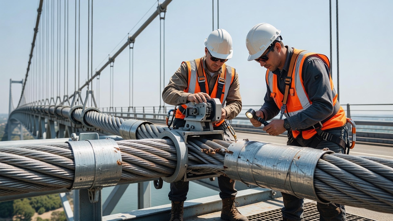
Main cables are fracture-critical members under the U.S. National Bridge Inspection Standards (NBIS) — meaning their failure would result in catastrophic collapse of the entire bridge. Unlike redundant structural systems with multiple load paths, the main cable has no backup. This classification imposes stringent inspection requirements: biennial hands-on inspection and thorough internal inspection beginning at 30 years of service, as codified by the Federal Highway Administration (FHWA) in 23 CFR Part 650 Subpart C.
The Air Spinning (AS) method is the traditional technique for constructing suspension bridge main cables, used on nearly all historic and early 20th-century suspension bridges. The process begins with the installation of catwalks — temporary suspended walkways that follow the cable path between anchorages and over the towers. These catwalks serve as working platforms for the entire cable spinning operation and are typically constructed from wire mesh supported by strand ropes.
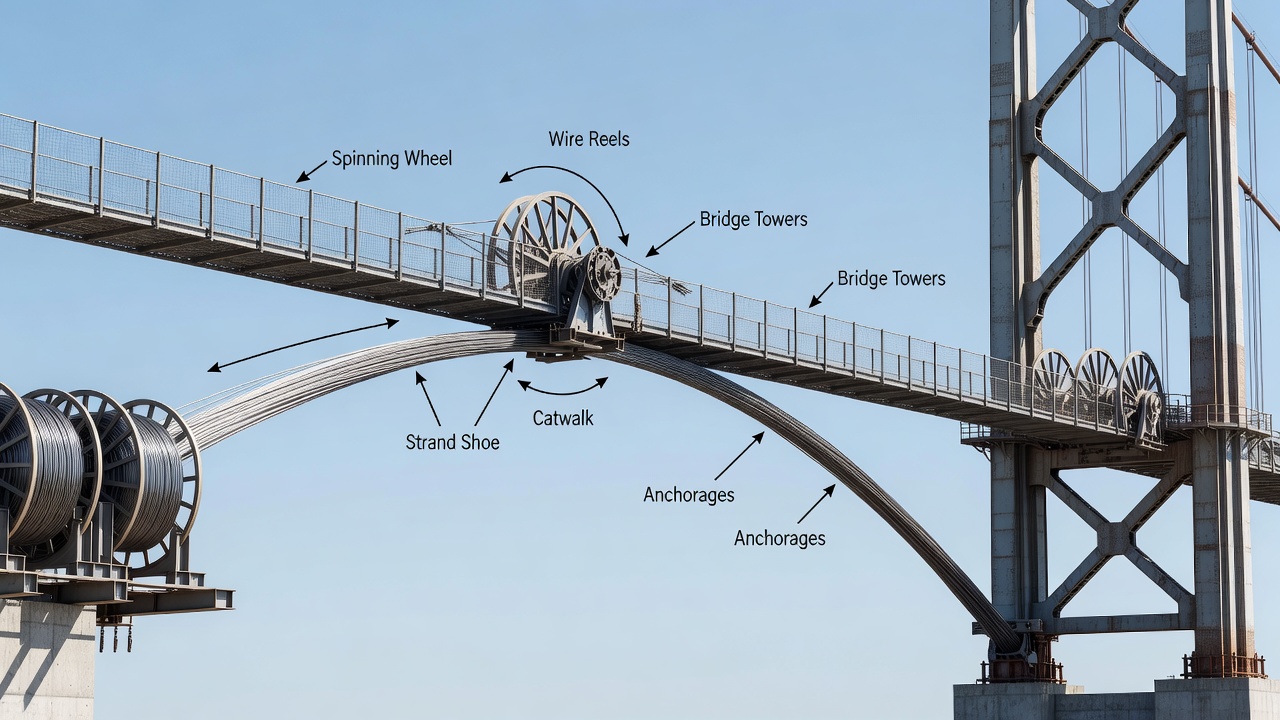
In the AS method, a single wire at a time is pulled across the span by a spinning wheel traveling on a continuous hauling rope running between anchorages. The wire is drawn from a stationary reel at one anchorage, loops around a strand shoe at the far anchorage, and returns, building up multiple wires in parallel to form a strand. Each loop of the spinning wheel places two wires — one going and one returning. The process repeats until the strand reaches its specified number of wires (typically between 200 and 500 wires per strand for historic bridges). The completed strand is then temporarily anchored at the strand shoe while spinning continues on adjacent strands.
Wire diameters are standardized at 5 mm (0.196 inches) for the vast majority of suspension bridge cables. Typical steel grades used are 1,570 MPa (225 ksi) for older bridges and up to 1,960 MPa (284 ksi) for modern high-strength applications. Each wire is coated with a zinc galvanizing layer — minimum 300 g/m² per ISO 19427 — to provide sacrificial corrosion protection. The zinc coating is the first line of defense against corrosion and must be intact for the wire to have its full design life.
The Golden Gate Bridge cable, constructed in 1935–1936 using the AS method, contains 61 strands per cable, each strand comprising 452 wires, for a total of 27,572 wires per cable. Each cable has a finished diameter of 92.4 cm (36.4 inches). The total length of wire in both main cables is approximately 129,000 km (80,000 miles). The Williamsburg Bridge (1903) was the first major suspension bridge to use the AS method in the United States.
After all strands are spun, the cable undergoes compaction — a hydraulic squeezing process that compresses the loosely bundled strands into a near-circular cross-section. Compaction removes interstitial air gaps and prepares the cable for wrapping. Compaction ratios (finished area divided by circumscribed area) typically reach 0.80–0.85, meaning about 15–20% of the cable cross-section remains as void space — which becomes critical for water ingress pathways. A typical 5 mm wire spacing results in approximately 20–25% void ratio before compaction, reduced to about 18–20% after compaction.
The Prefabricated Parallel Wire Strand (PPWS) method, also known as Factory-Made Strand, was developed to accelerate construction and improve quality control. In PPWS, strands are fabricated in a factory under controlled conditions, with wires laid parallel and strapped into a hexagonal cross-section. Each strand contains 61 to 127 individual wires (most commonly 91 or 127 wires for modern bridges). The strands are wound onto massive steel shipping reels — a single 127-wire strand reel for the Akashi Kaikyo Bridge weighed approximately 40 tonnes.
According to ISO 19427:2019 (Steel Wire for Parallel Wire Strand for Suspension Bridge), each prefabricated strand must satisfy strict tolerances: wire tensile strength within ±5% of specified value, galvanizing mass per unit area not less than 300 g/m², and wire diameter tolerance of ±0.06 mm. A red reference wire is included in each strand for twist detection — if the strand twists during handling, the red wire’s position deviation reveals the twist angle.
At the bridge site, PPWS strands are lifted from reels at the anchorage, pulled across the catwalk using a winch line, and placed into their designated position in the cable. Adjacent strands are bundled and compacted identically to AS cables. The PPWS method was pioneered on Japanese long-span bridges by the Honshu-Shikoku Bridge Authority (HSBA) and was used on the Akashi Kaikyo Bridge (world’s longest suspension span at 1,991 m), which has 290 prefabricated strands of 127 wires each per cable — totaling 36,830 wires per cable with a finished diameter of 112 cm (44.1 inches). The Great Belt Bridge (Storebaelt, Denmark) also used PPWS with 69 strands of 504 wires each per cable.
PPWS offers several advantages: factory quality control ensures uniform tension and wire properties, construction is faster (strands placed in days rather than months), and the hexagonal packing allows better compaction with lower void ratios (16–18%). However, PPWS requires heavy lifting equipment at the bridge site and specialized transport for the large reels.
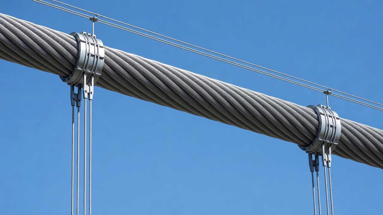
After either AS or PPWS construction is complete and the cable is compacted, cable bands are installed at precise intervals corresponding to hanger rope attachment points. Cable bands are cast-steel or ductile-iron split collars clamped around the main cable using high-strength bolts torqued to specific values (typically 600–900 N·m per bolt, depending on band size). The bands serve three functions: they maintain the circular shape of the cable, provide a connection point for the hanger ropes, and create a compressive seal against water ingress at the band location.
Hanger ropes, also called suspenders or suspender cables, are the secondary vertical cable elements that transfer the bridge deck’s gravity load to the main cable. Each hanger rope connects a cable band on the main cable to a deck connection point — typically on a floorbeam or girder at the deck edge. Hanger ropes are critical for load distribution but, unlike the main cable, are individually replaceable.
Two primary types of hanger rope construction are used:
| Rope Type | Construction | Advantages | Typical Diameter |
|---|---|---|---|
| Spiral Strand | Multiple layers of helically wound wires around a center wire; each layer wound in opposite direction | High axial stiffness; good fatigue resistance | 40–90 mm |
| Locked Coil | Outer layer(s) comprise Z-shaped (interlocking) wires that form a smooth, closed surface | Superior corrosion resistance; aerodynamic smoothness; highest strength density | 45–100 mm |
| Wire Rope (6x36 or similar) | Multiple strands of wires twisted around a fiber or wire core | Flexibility; lower cost; less axial stiffness | 30–70 mm |
The locked coil rope is the preferred type for modern suspension bridge hangers due to its superior corrosion resistance — the Z-shaped outer wires interlock to form a water-resistant barrier. Each Z-wire’s profile resembles the letter “Z” in cross-section, with adjacent wires fitting together like puzzle pieces, preventing water ingress between layers. Spiral strand ropes, while lacking interlocking outer wires, offer excellent axial stiffness and are widely used on older bridges.
Hanger ropes are terminated at each end with sockets. Common socket types include:
The socket-to-pin connection is a critical fatigue and corrosion location. Water can penetrate the socket interface and become trapped, creating a concentrated corrosion cell where the rope enters the socket. Inspection of the socket neck and pin area is a standard requirement in all suspension bridge inspection programs. A 2012 FHWA study identified socket corrosion as one of the most frequently overlooked risk areas.
Hanger ropes are installed with a precise dead load tension determined from structural analysis — the tension must be uniform across all hangers at the same longitudinal position to avoid distorting the deck profile. Tension adjustments are performed using hydraulic jacks at the deck connection, with hanger rope elongation measured and compared to design values.
Cable band clamping force is critical to hanger rope performance. The friction between the cable band and the main cable must resist the vertical component of the hanger force without slipping. Slippage of cable bands has occurred on several bridges when bolt tension was insufficient, causing the band to slide down the main cable under load. This typically manifests as a visible gap at the top edge of the band and requires emergency re-torquing.
Until the 1990s, suspension bridge main cables were protected by a multi-layer passive system applied immediately after compaction:
Despite these precautions, no wrapping system is completely watertight. Over decades of thermal cycling (expansion and contraction), the wrapping wire develops gaps. The red lead or zinc paste dries and cracks. Paint systems weather and develop pinholes. The result is that all suspension bridge cables constructed before the mid-1990s experienced some degree of water ingress and internal corrosion.
The breakthrough in main cable corrosion protection came from Japan in the 1990s. The Honshu-Shikoku Bridge Authority discovered that corrosion was occurring on cables only 7 years after construction — far earlier than anticipated. Despite improved wrapping systems, it was determined that complete watertight sealing was unachievable for cables exposed to the marine environment. The solution was active dehumidification — continuously maintaining the interior of the cable at a relative humidity below 40%, at which corrosion of galvanized steel practically ceases.
The cable dehumidification system consists of the following components:
The target condition for an active dehumidification system is below 40% RH at all points within the cable interior. At this level, the corrosion rate of galvanized steel is effectively zero. The chemical basis for this threshold is that the electrochemical corrosion reaction requires an electrolyte — liquid water — to support ion transport. Below 40% RH, only an adsorbed molecular layer of water exists on the steel surface, which cannot function as an electrolyte.
Dehumidification has proven remarkably effective. The Forth Road Bridge (Scotland), which discovered 8–10% strength loss due to corrosion in 2004, installed dehumidification in 2006–2007. Subsequent inspections in 2009, 2012, and 2015 confirmed that no new corrosion had occurred after installation. The rate of new wire breaks, detected by acoustic monitoring, dropped from dozens per year to near zero. Dehumidification arrested the corrosion that had been ongoing for 42 years.
The Akashi Kaikyo Bridge (Japan, opened 1998) was the first major bridge designed with integral dehumidification from construction. The Storebaelt East Bridge (Denmark, 1998) also incorporated dehumidification. Retrofit installations have been completed on the Severn Bridge (UK, first operational UK system), Humber Bridge (UK, world’s largest retrofitted system at the time), Verrazzano-Narrows Bridge (NYC, $249M contract awarded 2025), Chesapeake Bay Bridge (first full-length dehumidification in North America), Bear Mountain Bridge (NY), Mid-Hudson Bridge (NY), and Delaware Memorial Bridge.
Main cable inspection in the United States is governed by the National Bridge Inspection Standards (NBIS) under 23 CFR Part 650 Subpart C, the AASHTO Manual for Bridge Evaluation (MBE) , and the FHWA Primer for Inspection and Strength Evaluation of Suspension Bridge Cables (FHWA-IF-11-045, 2012). Internationally, the ISO 13822:2010 standard provides a framework for assessment of existing structures, including deterioration models for corrosion and fatigue, while PIARC (World Road Association) publishes technical reports on large bridge management.
The FHWA defines three levels of cable inspection:
| Level | Type | Interval | Description |
|---|---|---|---|
| 1 | Periodic Routine Visual | Every 24 months | External examination of wrapping, cable bands, paint condition |
| 2 | Hands-On Inspection | Every 24 months | Physical contact inspection of fracture-critical members — includes cable bands, sockets, saddles |
| 3 | Thorough Internal Inspection | At 30 years, then per evaluation | Removal of wrapping, wedge openings, wire inspection and sampling |
The NCHRP Report 534 (2004) — “Guidelines for Inspection and Strength Evaluation of Suspension Bridge Parallel Wire Cables” by Mayrbaurl and Camo — is the definitive technical reference for internal cable inspection. It establishes the recommended inspection team composition (chief investigator: professional engineer with suspension bridge expertise; chief inspector: professional engineer; cable inspectors: graduate engineers with 2–3 years experience; plus testing laboratory, metallurgical/corrosion consultants, and statistician as needed).
The thorough internal inspection of a main cable follows a rigorously defined protocol:
Step 1 — Test Panel Selection and Unwrapping. Based on engineering assessment, specific locations along the cable (test panels) are selected for internal examination. Typical test panels are located at: (a) mid-span, (b) quarter-span, (c) near towers (where bending stresses are highest), (d) at cable bands, and (e) at any visually suspicious areas. Each test panel is typically 1.5–3 m in length. The wrapping wire is carefully removed and saved for rewrapping.
Step 2 — Wedge Opening. Wooden or plastic wedges (hardwood wedges are traditional, HDPE wedges are modern alternatives) are driven into the cable at approximately 0.5 m spacing along the test panel. Eight wedge lines are established around the cable circumference — positioned at: top, bottom, left, right, upper-left, upper-right, lower-left, lower-right. Wedges are driven progressively, opening the cable to expose interior wires without damaging them. Opening force must be carefully controlled to avoid creating false wire breaks.
Step 3 — Visual Examination. All accessible wires in the opened test panel are visually inspected. The condition of each exposed wire is classified per the corrosion staging system:
| Stage | Condition | Description |
|---|---|---|
| 1 | Sound | Bright galvanizing intact; no rust |
| 2 | Light Corrosion | Surface zinc oxidation (white rust); no base metal attack |
| 3 | Moderate Corrosion | Red rust visible on wire surface; localized pitting < 0.5 mm deep |
| 4 | Severe Corrosion | Deep pitting > 0.5 mm; significant section loss; cracked wires |
Step 4 — Wire Sampling. A statistically significant number of wires are removed from each test panel for laboratory tensile testing. The sampling strategy must capture the variability across the cable cross-section — typically 3–5 wires from each wedge line, plus any wires with visible defects. Samples are labeled with position, orientation, and condition class.
Step 5 — Laboratory Testing. Wire specimens are tested for: ultimate tensile strength (UTS), yield strength, elongation at fracture, reduction of area, and fracture surface examination (SEM for micro-cracks). Galvanizing thickness is measured. Stress-strain curves are generated for comparison to original wire properties.
Step 6 — Strength Evaluation. The wire condition data is used to estimate remaining cable strength. Two principal methods are used:
Magnetic Flux Leakage (MFL) testing is the primary NDT method for detecting cross-sectional area loss in main cables. An MFL scanner is passed along the cable, inducing a magnetic field and measuring flux leakage at areas of section loss (corrosion pits, wire breaks). MFL can detect area losses as small as 2–5% of the total cross-section but cannot reliably distinguish between individual broken wires and general corrosion. MFL is used as a screening tool to identify areas requiring targeted wedge opening.
Guided Wave Ultrasonic Testing (GWUT) uses ultrasonic waves propagated along individual wires to detect defects up to 60 m from the sensor location. GWUT is effective for detecting transverse cracks and broken wires in accessible cable segments. The technique is limited by signal attenuation at cable bands and saddles, and by the complexity of signal interpretation in multi-wire cables.
Acoustic Emission (AE) Monitoring is a continuous, real-time method for detecting wire breaks as they occur. Piezoelectric sensors (typically resonant at 40–100 kHz) mounted on the cable detect the elastic stress waves generated by a wire fracture. Sensor spacing is typically 5–15 m along the cable. Time-of-flight analysis of wave arrival at multiple sensors localizes the break within ±0.5–2 m. Modern AE systems use multi-parameter filtering (amplitude, energy, counts, frequency content) to distinguish wire breaks from environmental noise (wind, rain, traffic, thermal expansion). The Humber Bridge and Storebaelt Bridge have the largest installed AE monitoring systems. The Forth Road Bridge AE system detected 93 wire breaks by 2015, then 24 additional breaks in a cluster at the south-east tower leg — providing early warning for targeted inspection.
Wire breaks in suspension bridge main cables occur through several mechanisms. Understanding the failure mode is essential for predicting remaining life.
Corrosion fatigue is the most common wire break mechanism. Cyclic tensile stress from traffic loading (live load), combined with a corrosive environment (water + chlorides at the wire surface), initiates micro-cracks at corrosion pits. These cracks propagate under continued cyclic loading until the remaining cross-section cannot sustain the static dead load, causing sudden fracture. The critical crack size for a 5 mm wire subjected to typical cable tension is approximately 1–2 mm deep.
Stress Corrosion Cracking (SCC) occurs when three conditions are simultaneously present: high-tensile stress (from cable dead load), a susceptible material (high-strength steel), and a corrosive environment. SCC produces branched, intergranular or transgranular cracks that propagate slowly under sustained load. SCC is particularly dangerous because cracks can reach critical size without visible warning.
Hydrogen embrittlement is a catastrophic failure mode in which atomic hydrogen diffuses into the steel lattice, reducing ductility and causing brittle fracture at stresses well below the wire’s normal tensile strength. Hydrogen is generated by cathodic reactions in the corrosion process. High-strength steel wires (UTS > 1,500 MPa) are especially susceptible.
Fretting fatigue occurs at cable band locations where microscopic relative movement between individual wires under cyclic loading produces surface wear (fretting), leading to localized stress concentrations and fatigue crack initiation. Fretting fatigue clusters are most commonly found at wires adjacent to cable band edges.
The corrosion rate of galvanized steel in a humid environment is dramatic: at RH above 60% and temperatures above 0°C, the corrosion rate accelerates exponentially. Below 40% RH, corrosion effectively stops. This is the fundamental justification for cable dehumidification — it changes the cable interior environment from corrosive to inert.
The assessment of remaining cable strength follows a rigorous statistical approach. For the NCHRP 534 method, the cable strength factor S is computed as:
S = (N_s × σ_avg × A_w × K_r) / T_d
where N_s is the number of sound wires, σ_avg is the average tensile strength from wire tests, A_w is the average wire cross-sectional area, K_r is a redevelopment factor (accounting for friction transfer at cable bands for broken wires), and T_d is the design cable tension at the section under evaluation.
The anchorage is the termination point of the main cable, typically a massive concrete gravity structure or rock tunnel that resists the cable tension force. Inside the anchorage, the main cable separates into its individual strands at the splay chamber.
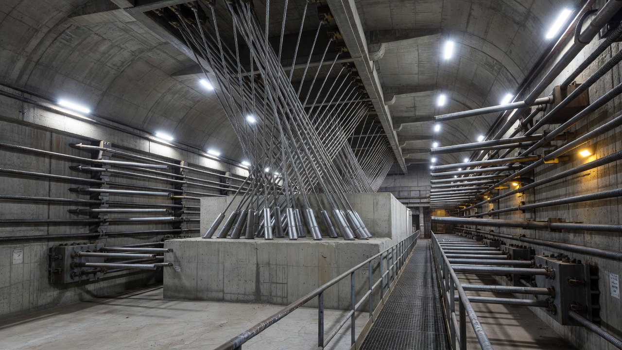
Key inspection items in the anchorage and splay chamber include:
The splay chamber must be inspected at the same interval as the main cable internal inspection. Dehumidification of the splay chamber is now standard practice, with dry air injected at the cable entry seal and exhausted at the anchorage rear wall.
A modern cable dehumidification system is a sophisticated active corrosion control installation. The system design must account for the specific geometry, void ratio, and environmental exposure of each bridge’s main cables.
The air handling unit houses the desiccant dryer, fans, filters, and control electronics. Desiccant dryers use a rotor (a wheel-shaped matrix impregnated with silica gel or molecular sieve) that rotates slowly through two sectors: the process sector (where moisture is adsorbed from the incoming air) and the regeneration sector (where heated air at 120–150°C drives off the adsorbed moisture). The rotor continuously cycles between the two sectors, providing a steady stream of dry air. Typical output air dew point is −30°C to −40°C, corresponding to less than 1% RH at ambient temperatures.
Distribution piping runs from the AHU to injection points along the cable. HDPE pipes with electro-fusion joints are standard — they provide airtight connections that do not leak moisture into the system. Pipes are routed along catwalks or attached to hanger ropes using stainless steel clamps. For bridges with long spans, pressure losses in the distribution system must be calculated to ensure adequate air flow at the furthest injection point.
Injection sleeves are custom-fabricated stainless steel assemblies that wrap around the cable circumference, forming an airtight plenum. The sleeve has a rubber gasket that seals against the elastomeric cable wrap. Dry air enters through a connection port and is forced into the cable interior through numerous small holes or slots in the sleeve, directed axially along the cable. The insertion of zinc wedges or spacer wires at the injection location creates air flow channels within the cable cross-section.
Zone design divides the cable length into independently controlled sectors. The optimal zone length depends on cable void ratio (air permeability), injection air pressure (typically 5–15 kPa above atmospheric), and target air exchange rate. Zones of 100–300 m are typical. Each zone has at least one injection point and one exhaust point. Zone isolation is achieved by installing internal dams (temporary blocking materials such as expanding foam wrapped in mesh) between zones during installation.
Monitoring includes: temperature and RH sensors at each injection and exhaust point, air pressure sensors at injection sleeves, air velocity sensors at exhaust ports, and ambient weather station data. Modern systems transmit data to cloud-based monitoring platforms with automated alarms when RH exceeds the 40% threshold in any zone. Historical data trending allows operators to detect developing problems before they become critical.
Retrofit installation requires significant access work. On the Severn Bridge, the installation required (a) removing existing wrapping and paint, (b) applying the new elastomeric sealing wrap, (c) installing injection sleeves at cable bands, (d) routing 72 separate sections of HDPE pipe through the bridge structure, (e) constructing the plant room inside the bridge — requiring 5 days of work by a 3-person team just for the plant room, and (f) complying with heritage listing requirements (the Severn Bridge is a listed structure, requiring special approvals for drilling holes for ductwork).
Modern suspension bridges incorporate comprehensive Structural Health Monitoring (SHM) systems that integrate main cable monitoring with global structural monitoring.
| Sensor Type | Parameter Monitored | Typical Specification |
|---|---|---|
| Load Cells | Cable tension at anchorages | 5,000–20,000 kN capacity, ±0.5% accuracy |
| Tilt Meters | Tower inclination | ±0.01° resolution |
| Accelerometers | Structural vibration, wind response | 0.01–20 Hz range |
| GPS (RTK) | Deck displacement, cable sag | ±5 mm horizontal, ±10 mm vertical |
| Temperature Sensors | Cable and ambient temperature | −30°C to +70°C, ±0.5°C |
| AE Sensors | Wire breaks in real time | 40–100 kHz resonant sensors |
| Fiber Optic (FBG) | Strain in critical wires | ±1 µε resolution |
| Distributed Temperature Sensing (DTS) | Cable temperature profile | 1 m spatial resolution, ±0.1°C |
| Distributed Acoustic Sensing (DAS) | Acoustic events along cable | 1 m spatial resolution |
Load cells at the anchorage bearing plates provide continuous measurement of total cable tension. Changes in tension indicate: settling or movement of anchorages, redistribution of load between cables (if one cable is losing stiffness due to wire breaks), or thermal effects.
Acoustic emission monitoring has become standard on major suspension bridges. The system uses 40–100 kHz resonant sensors mounted on the cable with custom curved-surface coupling plates that match the cable diameter. Sensor spacing of 5–15 m provides localization accuracy of ±0.5–2 m for wire break events. The system must distinguish wire breaks from environmental noise using multi-parameter filtering (time-of-flight correlation, waveform analysis, frequency content, amplitude thresholding). Standards such as JT/T 1037-2022 (Chinese Highway Bridge Structure Monitoring) specify alarm thresholds: Level 2 (wire break occurs), Level 3 (wire break rate > 2% per year).
Real-time kinematic (RTK) GPS monitoring of deck elevation provides indirect cable condition data. If the deck sags below its design profile, it indicates either cable elongation (from wire creep or corrosion section loss) or hanger rope relaxation. RTK GPS achieves ±5 mm horizontal and ±10 mm vertical accuracy with a 20 Hz update rate.
Williamsburg Bridge (New York, 1903) — The 1987 internal inspection revealed several hundred broken or severely corroded wires, with concentrated corrosion in the lower half of both cables. This inspection was a watershed moment for the bridge engineering community — it demonstrated that severe internal corrosion can proceed undetected beneath an intact wrapping system. The bridge was subsequently taken out of subway service and a comprehensive rehabilitation program was implemented.
Forth Road Bridge (Scotland, 1964) — First internal inspection in 2004 revealed 8–10% cable strength loss, predicted to require live load restrictions by 2017 and full closure to light vehicles by 2021. An acoustic monitoring system was installed in 2006. Dehumidification was installed 2006–2007 and proved effective — inspections in 2009, 2012, and 2015 found no new corrosion progression. A cluster of 24 wire breaks at the south-east tower leg in early 2015 triggered a targeted inspection. The bridge continues in service as a public transport corridor following the 2017 opening of the Queensferry Crossing.
Golden Gate Bridge (San Francisco, 1937) — Regular internal inspections since the 1990s have found surprisingly good cable condition considering 80+ years of marine exposure. The bridge benefits from San Francisco’s relatively dry summer climate and low chloride levels compared to East Coast bridges. Dehumidification is being evaluated for future installation.
Verrazzano-Narrows Bridge (New York, 1964) — The Metropolitan Transportation Authority (MTA) awarded a $249 million contract in 2025 for a comprehensive cable dehumidification system installation — the largest such contract in North America to date. The project covers both main cables across the 1,298 m main span.
Akashi Kaikyo Bridge (Japan, 1998) — World’s longest suspension span at 1,991 m. Designed with integral dehumidification from construction. First major bridge to incorporate active corrosion control as a design feature rather than a retrofit. The cable inspection program established the PPWS method inspection protocols now used worldwide.
Storebaelt East Bridge (Denmark, 1998) — Main span 1,624 m. PPWS construction with integral dehumidification and comprehensive AE monitoring. The monitoring system has provided some of the longest continuous datasets on wire break rates in dehumidified cables.
Humber Bridge (UK, 1981) — Longest suspension span in the world at the time (1,410 m). Largest retrofitted dehumidification and AE monitoring system as of 2011 installation. The combination of AE monitoring and dehumidification on the Humber Bridge has demonstrated the clear correlation between RH control and wire break rate reduction.
Tsing Ma Bridge (Hong Kong, 1997) — Dual-purpose road and rail suspension bridge with main span 1,377 m. Comprehensive SHM system incorporating anemometers, strain gauges, accelerometers, GPS, and temperature sensors. The monitoring data has been used extensively for wind and structural response research.
The cumulative experience from these major inspection programs has established that: (1) internal cable corrosion is inevitable for cables without dehumidification; (2) dehumidification is the only proven method to arrest ongoing corrosion; (3) acoustic monitoring provides early warning of trouble spots; and (4) the critical locations for wire breaks are consistently at tower saddles, cable bands, and splay chambers — the points where water ingress is most likely and where fretting fatigue stresses are highest.
Professional bridge cable inspection requires specialized knowledge of corrosion mechanisms, nondestructive testing methods, and strength evaluation protocols. Contact our team for expert guidance on suspension bridge cable assessment, monitoring systems, and maintenance planning.
Stay cables are high-strength steel tension elements connecting the bridge pylon to the deck in cable-stayed bridges, forming the primary load path. Cable condi...
Bridge girders are the primary horizontal load-carrying beams supporting the bridge deck, spanning between piers and abutments. Common types include steel I-gir...
A prestressing tendon is a high-strength steel element — typically seven-wire strand, wire, or bar — used in prestressed or post-tensioned concrete to apply per...