Post-Tensioning (PT) in Concrete Structures
Post-tensioning (PT) is a method of prestressing concrete where high-strength steel tendons are tensioned after concrete hardening, applying compressive stress ...
30 min read
Reinforcement
Concrete
+3
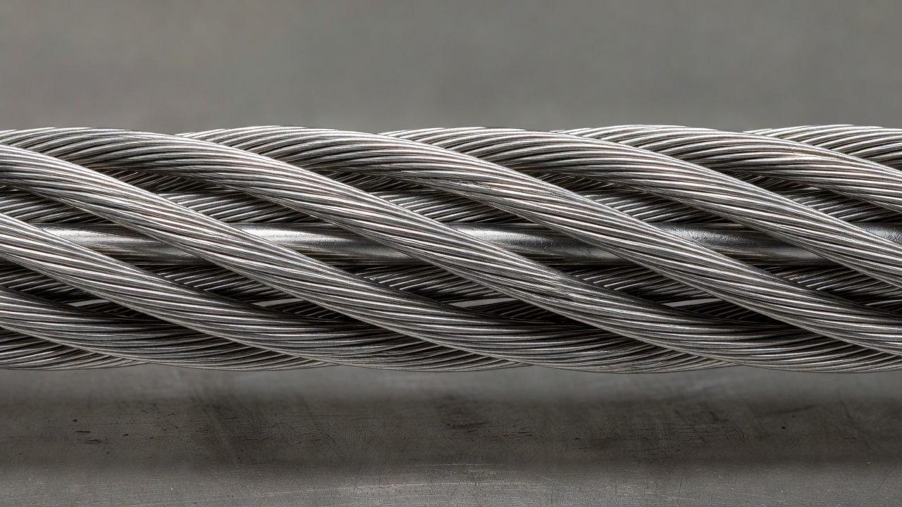
A prestressing tendon is a high-strength steel element — typically seven-wire strand, wire, or bar — used in prestressed or post-tensioned concrete to apply permanent compressive force to the structure. Tendon condition, including corrosion, fracture, and loss of prestress, is a primary bridge inspection concern. Detailed coverage of tendon types, material properties, corrosion mechanisms, and NDT methods.
A prestressing tendon is a high-strength steel tension element used to apply a permanent compressive stress to concrete in prestressed and post-tensioned structures. The tendon is tensioned — either before concrete placement (pretensioning) or after concrete has cured (post-tensioning) — and the force is transferred into the concrete through mechanical bond, end anchorages, or both. This induced compression counteracts the tensile stresses that will develop under service loads, enabling longer spans, thinner sections, and improved crack control compared to conventionally reinforced concrete.
Prestressing tendons are manufactured in three principal forms, each governed by distinct material standards and suited to specific structural applications.
Seven-wire strand is by far the most common tendon type. It consists of a single straight center wire surrounded by six helically wound outer wires. The helical wrapping imparts mechanical interlock with grout or concrete and provides flexibility for handling. Strand is manufactured to ASTM A416 / AASHTO M203 in two grades: Grade 250 (minimum ultimate tensile strength of 250 ksi / 1725 MPa) and Grade 270 (270 ksi / 1860 MPa). Grade 270 is the standard for nearly all modern bridge and building construction. The strand is produced in nominal diameters of 0.375, 0.438, 0.500, and 0.600 inches (9.53, 11.11, 12.70, and 15.24 mm). The 0.5-inch (12.7 mm) and 0.6-inch (15.24 mm) diameters are the most widely used in bridge post-tensioning. Two types of strand exist: low-relaxation (the default) and stress-relieved (normal-relaxation). Low-relaxation strand undergoes a continuous thermal-mechanical treatment after stranding to achieve superior relaxation performance, with relaxation losses limited to less than 2.5% at 1000 hours when initially stressed to 70% of ultimate tensile strength. Stress-relieved strand, which receives only thermal treatment, must be specifically ordered and has higher relaxation losses.
Individual wire is a cold-drawn high-carbon steel wire manufactured to ASTM A421. Wires are round and typically range from 0.192 to 0.276 inches (4.88 to 7.01 mm) in diameter. Individual wires are used in pretensioned elements such as hollow-core slabs, railroad ties, and circular prestressed tanks where wires are wound under tension. Wire may be plain, indented, or crimped to improve bond with concrete. ASTM A421 defines two types: Type BA (stress-relieved, cold-drawn) and Type WA (stress-relieved, cold-drawn, low-relaxation).
High-strength bar is a threaded or smooth alloy steel bar manufactured to ASTM A722. Bars range from 0.625 to 3.625 inches (15.875 to 92.075 mm) in nominal diameter and are available in Grades 150 and 160 (minimum ultimate tensile strengths of 150 ksi / 1035 MPa and 160 ksi / 1100 MPa). Bars are used in segmental bridge construction, temporary post-tensioning during erection, rock and soil anchors, and structural repair. Bar tendons are typically stressed using hydraulic jacks that thread onto the bar end, and force is transferred through bearing plates and nuts at the anchorages.
Tendon configuration also distinguishes between bonded and unbonded systems. In bonded post-tensioning, the tendon is installed inside a duct (corrugated steel or plastic) that is subsequently filled with cementitious grout. The grout provides corrosion protection through its highly alkaline environment (pH > 12.5) and establishes full bond between the tendon and surrounding concrete. If a wire in a bonded tendon fractures, the grout distributes the force release along the tendon length, preventing sudden loss of capacity at the anchor. In unbonded post-tensioning, the strand is individually sheathed in plastic and coated with corrosion-inhibiting grease or wax. No grout is used, and the tendon is free to move relative to the concrete. The entire prestressing force is transferred at the end anchorages. Unbonded systems are widely used in buildings, parking structures, and slabs-on-grade. Each system presents distinct inspection challenges and corrosion protection requirements.
Prestressing steel is fundamentally different from conventional reinforcing steel (rebar) in both mechanical properties and metallurgy. The high strength required for efficient prestressing is achieved through a combination of high carbon content, cold drawing, and thermal treatment.
The most common prestressing steel, Grade 270 seven-wire strand, has a minimum ultimate tensile strength of 270,000 psi (1860 MPa). This is approximately four times the yield strength of Grade 60 reinforcing bar (60 ksi / 420 MPa). The yield strength is defined at 1% extension under load (not the traditional 0.2% offset used for other steels), reflecting the absence of a well-defined yield plateau in cold-drawn wire. For low-relaxation strand, minimum yield strength is 90% of the specified breaking strength. For stress-relieved strand, it is 85%. The modulus of elasticity of prestressing strand is approximately 28,500 ksi (196,500 MPa) — similar to conventional steel — but the stress-strain curve is nearly linear up to about 85% of ultimate strength, with no sharp yield point.
Low-relaxation property is the most significant material advancement in modern prestressing steel. Relaxation is the time-dependent reduction of stress in steel held at constant strain. In stress-relieved strand, relaxation losses can reach 5-8% at 1000 hours when stressed to 70% of ultimate. Low-relaxation strand, through its continuous thermal-mechanical treatment (also called stabilizing treatment), reduces 1000-hour relaxation to less than 2.5% under the same conditions. This treatment involves heating the strand under tension to approximately 350-400&C (660-750&F), which stabilizes the dislocation structure in the cold-drawn wire matrix and dramatically reduces long-term relaxation. The long-term relaxation after 50 years, extrapolated per ASTM E328, is typically 5-8% for low-relaxation strand versus 10-15% for stress-relieved strand.
The metallurgy of prestressing steel is critical to understanding its performance and failure modes. Prestressing wire is made from high-carbon steel with a carbon content of 0.75-0.85%, manganese of 0.60-0.90%, and silicon of 0.15-0.35%. The steel is hot-rolled into rod, then cold-drawn through a series of progressively smaller dies. Cold drawing reduces the cross-sectional area by 80-90%, producing a heavily deformed pearlitic microstructure with the ferrite and cementite lamellae aligned parallel to the wire axis. This microstructure gives the steel its exceptional strength but also creates a material that is highly sensitive to hydrogen. Any atomic hydrogen that enters the steel — from corrosion reactions, cathodic protection, or galvanizing processes — can diffuse along the grain boundaries and accumulate at inclusions, leading to hydrogen embrittlement and sudden brittle fracture under sustained tensile stress.
| Property | Grade 250 Strand (ASTM A416) | Grade 270 Strand (ASTM A416) | High-Strength Bar (ASTM A722 Grade 150) |
|---|---|---|---|
| Min. Ultimate Tensile Strength | 250 ksi (1725 MPa) | 270 ksi (1860 MPa) | 150 ksi (1035 MPa) |
| Min. Yield Strength (1% extension) | 212.5 ksi (1465 MPa) — low relax. | 243 ksi (1675 MPa) — low relax. | 130 ksi (895 MPa) |
| Modulus of Elasticity | 28,500 ksi (196,500 MPa) | 28,500 ksi (196,500 MPa) | 30,000 ksi (207,000 MPa) |
| Relaxation at 1000 hours (70% UTS) | <2.5% (low relax.) | <2.5% (low relax.) | Varies |
| Typical Carbon Content | 0.75-0.85% | 0.75-0.85% | 0.40-0.55% |
| Core wire diameter (0.6" strand) | — | 0.128 in (3.25 mm) | N/A |
| Outer wire diameter (0.6" strand) | — | 0.116 in (2.95 mm) | N/A |
The geometry and routing of a prestressing tendon within a concrete member are carefully designed to maximize structural efficiency. The tendon profile is the vertical or horizontal path that the tendon follows along the length of the member. In simply supported beams, tendons typically follow a parabolic or draped profile — low at midspan (where maximum positive moment requires eccentric compression at the bottom fiber) and rising toward the supports (where the eccentricity is reduced or reversed to control end stresses). In continuous spans, tendon profiles are often segmented parabolas with inflection points near the interior supports.
The tendon profile directly affects the stress distribution in the concrete. The prestressing force applied at an eccentricity e from the concrete centroid induces both axial compression (P/A) and bending moment (P×e/S) in the member. By varying the eccentricity along the span, the designer achieves a balanced stress state under service loads. ACI 318 and AASHTO LRFD Bridge Design Specifications provide detailed procedures for selecting tendon profiles and calculating the resulting concrete stresses at transfer and under service conditions.
Each tendon occupies a duct — a corrugated metal or plastic tube that provides a void for tendon installation and subsequent grouting. Duct diameter is typically 2.5 to 3.5 times the nominal tendon diameter to allow adequate clearance for strand installation and grout flow. Metal ducts are spirally corrugated galvanized steel; plastic ducts are high-density polyethylene (HDPE) or polypropylene. Plastic ducts are increasingly specified for enhanced corrosion protection and electrical isolation. Ducts are positioned and tied to the reinforcement cage before concrete placement, with careful attention to maintaining the designed profile, preventing damage during concreting, and ensuring watertight joints at splices.
The anchor block or anchorage zone is the region of the member where the prestressing force is transferred from the tendon to the concrete. In post-tensioning, the anchorage consists of a cast or machined steel bearing plate with conical wedge holes (for strand) or threaded couplers (for bars). The bearing plate distributes the concentrated tendon force over a sufficient area to keep bearing stresses within acceptable limits. The concrete immediately behind the anchorage is heavily reinforced with spiral or grid reinforcement to resist the bursting and spalling forces generated by the stress concentration. ACI 318 Chapter 17 prescribes the design of anchorage zones for post-tensioned members.
Grout inlets and outlets are provided at strategic locations along the duct for injecting cementitious grout after stressing. Inlet and outlet pipes (typically 1 to 1.5 inches in diameter) are installed at tendon high points (for venting air during grouting) and low points (for grout injection). All inlets and outlets must be equipped with positive shut-off valves to contain grout pressure during injection and to prevent loss of protection if the pipe is later damaged. The FHWA Post-Tensioning Tendon Installation and Grouting Manual (FHWA-NHI-13-026) provides comprehensive requirements for the design, installation, and testing of grouting systems.
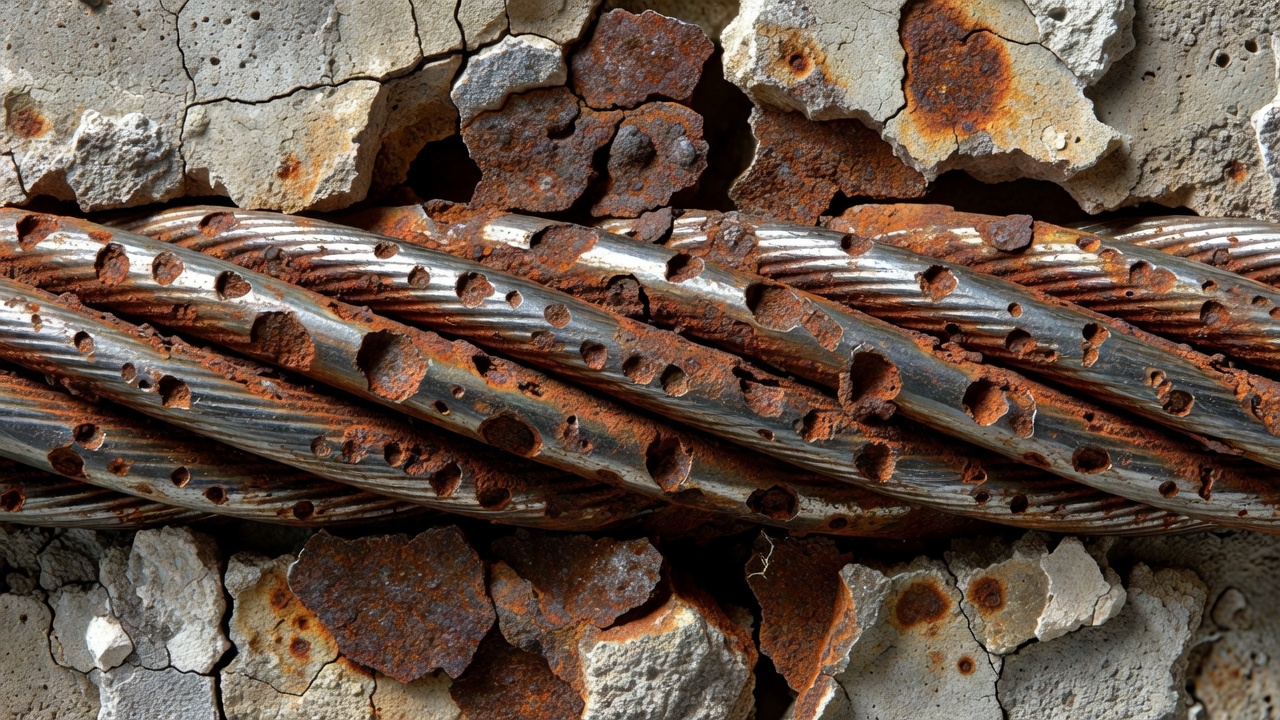
Corrosion of prestressing tendons is a fundamentally more serious condition than corrosion of conventional reinforcement. A prestressing tendon operates at 70-80% of its ultimate tensile strength. Any loss of cross-sectional area due to corrosion directly increases the tensile stress in the remaining steel, accelerating the failure process. Furthermore, the high-strength steel microstructure used in tendons makes them susceptible to specialized corrosion mechanisms that do not affect mild steel.
Chloride-induced pitting corrosion is the most common and dangerous corrosion mechanism for tendons in service. Chloride ions (Cl⁻) from deicing salts, marine spray, or brackish water penetrate the concrete cover through diffusion or capillary absorption. When the chloride concentration at the tendon depth reaches a critical threshold (typically 0.2-0.4% by weight of cement, depending on the steel type and environmental conditions), the passive oxide film that normally protects steel in the alkaline concrete environment (pH 12.5-13.5) is locally destroyed. The result is highly localized pitting attack. Pits can propagate rapidly because the small anodic area at the base of the pit drives a high corrosion current density to the surrounding passive steel. A pit that penetrates just 1-2 mm into a 5 mm diameter wire can reduce the load-carrying capacity by 20-30% because the notch effect concentrates stress at the pit root. Chloride-induced corrosion is typically accompanied by rust staining and concrete cracking, but by the time these symptoms appear, significant section loss may have already occurred.
Carbonation of grout or concrete reduces the pH of the environment surrounding the tendon. Carbon dioxide (CO₂) from the atmosphere diffuses into the concrete or grout and reacts with calcium hydroxide to form calcium carbonate, lowering the pH from 12.5-13.5 to approximately 8-9. At this pH, the passive film on the steel is no longer stable, and general corrosion can initiate if moisture and oxygen are present. Carbonation proceeds slowly in dense, well-compacted concrete but can advance rapidly in poorly consolidated grout within post-tensioning ducts. Inadequate grouting — where voids remain in the duct after injection — creates pathways for CO₂ and moisture to reach the tendon directly.
Stray current corrosion occurs when an external direct current (DC) passes through the concrete and tendon system. Sources of stray current include electric rail transit systems, cathodic protection systems on adjacent structures, welding operations, and grounding faults. The tendon acts as an electrical conductor; where current leaves the tendon and enters the surrounding electrolyte (grout or concrete), anodic conditions develop and metal dissolves at an accelerated rate. Stray current corrosion is typically concentrated and can progress rapidly, producing deep pits over short periods.
Hydrogen embrittlement (HE) is the most catastrophic failure mechanism for prestressing tendons. Atomic hydrogen (H) — not molecular hydrogen (H₂) — is absorbed into the steel lattice, where it diffuses to regions of high triaxial stress, typically at crack tips or metallurgical inclusions. The accumulated hydrogen reduces the cohesive strength of the iron lattice, causing brittle fracture at stresses well below the steel’s normal tensile strength. Sources of hydrogen include corrosion reactions (where hydrogen is produced at the cathodic site), overprotection from cathodic protection systems (excessive negative potential producing H₂ gas at the steel surface), and acid cleaning or pickling operations. The high carbon content and cold-drawn microstructure of prestressing steel make it one of the most hydrogen-sensitive engineering materials. A hydrogen embrittlement failure is sudden and complete — the tendon fractures with no visible warning on the external surface of the concrete.
Stress corrosion cracking (SCC) is the growth of cracks in a material under the combined action of sustained tensile stress and a specific corrosive environment. For prestressing steel, SCC typically requires a threshold stress (often above 50-60% of ultimate strength) and the presence of specific aggressive species such as nitrates, carbonates, or chlorides. Cracks propagate along the prior austenite grain boundaries (intergranular) or through the grains (transgranular), depending on the steel composition and environment. The fracture surface of SCC failures in prestressing steel shows characteristic features: a brittle fracture zone with little or no ductility, often with corrosion products on the crack faces. SCC progresses slowly until the remaining cross-section can no longer support the applied load, at which point final fracture occurs instantaneously.
Corrosion fatigue is the combined effect of cyclic loading (traffic loads on bridges) and a corrosive environment. The fatigue life of prestressing steel is dramatically reduced in the presence of even mild corrosion. A corroded tendon that might have an infinite fatigue life in air can fail in fewer than 10⁶ cycles in a corrosive environment. The corrosion pits act as stress raisers that nucleate fatigue cracks, and the aggressive environment accelerates crack propagation rates.
Assessment of tendon condition in existing structures is one of the most challenging problems in bridge engineering. Unlike conventional reinforcement, tendons are often inaccessible for direct inspection, and corrosion can progress undetected for years. A comprehensive NCHRP study (Project 10-53) reviewed global NDT technology and identified several methods with practical applicability.
Visual inspection remains the first line of assessment. Exposed portions of tendons at anchorages, intermediate stressing points, and coupling joints are examined for signs of corrosion, cracking, rust staining, and broken wires. At unbonded tendon anchorages in buildings and parking structures, the grease cap can be removed and the wedges and strand tails inspected directly. However, visual inspection alone is insufficient — NCHRP studies confirm that deterioration in embedded tendon condition is often not reflected by distress visible on the concrete surface.
Acoustic emission (AE) monitoring detects wire breaks in bonded and unbonded tendons by sensing the elastic stress waves released when a wire fractures. Sensors (piezoelectric transducers) are mounted on the concrete surface or on exposed tendon segments, and the AE system continuously monitors for characteristic burst signals associated with brittle wire fracture. The technique has been successfully applied on segmental bridge tendons in Europe and North America. AE can locate the approximate position of a wire break through time-of-flight triangulation between multiple sensors. One limitation is that AE monitors only active damage progression — it cannot detect pre-existing corrosion or section loss.
Magnetic flux leakage (MFL) is the most promising method for quantitative assessment of strand condition in pretensioned girders. The technique works by magnetically saturating the steel strand and then scanning for leakage flux that occurs at points of reduced cross-section (from corrosion pitting, cracking, or broken wires). MFL probes are pulled along the concrete surface, and the magnetic field perturbations are recorded and analyzed. The NCHRP 10-53 study concluded that recent advances in MFL equipment and data interpretation could enable automated NDT of strand in standard pretensioned girders, which represent roughly one-third of the concrete bridge inventory. MFL is most effective when the tendon is straight and at a relatively uniform cover depth.
Radiography (X-ray or gamma-ray) produces a two-dimensional image of the tendon on radiographic film or digital detector. Gammagraphy using Iridium-192 or Cobalt-60 sources can penetrate up to 600-800 mm of concrete and image internal tendons, ducts, and anchorages. Radiography can reveal grout voids, broken wires, corrosion pitting, and duct damage. The method requires access to both sides of the member and strict safety controls for radiation exposure.
Ultrasonic testing (UT) using low-frequency shear wave transducers can detect corrosion pitting, cross-section loss, and broken wires in embedded tendons. Techniques include pulse-echo and pitch-catch configurations. The concrete cover attenuates the ultrasonic signal, limiting the effective inspection depth to approximately 200-400 mm. The closely spaced wires in a multi-strand tendon create multiple reflective interfaces that complicate signal interpretation.
Ground penetrating radar (GPR) with frequencies of 1.0-2.6 GHz can locate ducts and identify voids in grouted tendons. Voids in grout produce strong reflections due to the air-grout dielectric contrast. GPR cannot directly image the steel condition but is valuable for identifying areas where corrosion protection has been compromised by inadequate grouting.
Electrochemical methods assess the corrosion activity of embedded steel. Half-cell potential mapping (ASTM C876) measures the electrical potential of the tendon relative to a reference electrode placed on the concrete surface. Potentials more negative than -350 mV vs. Cu/CuSO₄ indicate a high probability of active corrosion. Linear polarization resistance (LPR) measurements can estimate the instantaneous corrosion rate of the tendon. These methods require an electrical connection to the tendon, which may be accessible only at anchorages.
Electrical time domain reflectometry (ETDR) was investigated by Swiss researchers as a method for detecting corrosion in bonded tendons. The technique sends high-frequency electrical pulses along the strand and analyzes reflections caused by impedance discontinuities at defect locations. The NCHRP 10-53 study concluded that ETDR is not suitable for bonded tendons because the conductive grout and surrounding concrete damp and disperse the signal, preventing reliable defect detection.
A tendon fracture is a sudden, often catastrophic event. When a high-strength wire under 70-80% of its ultimate strength breaks, the elastic energy stored in the wire is released nearly instantaneously. In bonded tendons, the grout mitigates the energy release by transferring the force along the tendon length through bond. The broken wire may retract only a short distance before being restrained by grout, and the remaining wires in the strand continue to carry the load — although at a higher stress level.
In unbonded tendons, a fracture is more consequential. The entire strand is free to move within its sheath, and a complete strand fracture at an anchorage releases the full prestressing force at that location. The strand may whip within the sheath, causing localized damage to adjacent concrete. The abrupt loss of prestress at the fractured tendon can cause the slab or beam to deflect suddenly, potentially leading to punching shear failure in flat slabs or flexural cracking in beams.
The consequences of a tendon fracture depend on the structural system, the number of tendons, and the redundancy of the member. In a bridge girder with 20 tendons, the fracture of one tendon may reduce the capacity by 5-10%, which may be tolerable if the member has reserve strength. In a building slab with only two or three tendons per bay, a single fracture can represent a loss of 30-50% of the prestressing force, potentially triggering collapse. The failure of unbonded post-tensioned tendons in parking structures has been documented in numerous case histories, often linked to corrosion at the anchorage where moisture and chlorides collect.
Loss of prestress is the reduction of the effective tensile force in a tendon from its initial jacking value to the sustained value that exists at any point during the structure’s service life. Losses are classified as immediate (occurring during or immediately after stressing) and time-dependent (occurring over years to decades).
Immediate losses include elastic shortening of the concrete as the prestress is applied (in pretensioned members), friction losses between the tendon and its duct during stressing (in post-tensioned members), and anchorage set (the slight pull-in of the wedges when the jack is released). Friction losses are calculated using the wobble coefficient (k) and curvature friction coefficient (μ), which depend on the duct material and tendon type. Post-tensioning specifications typically require stressing records showing both jacking force and measured elongation to confirm that friction losses are within design assumptions.
Time-dependent losses result from four interacting phenomena:
Concrete shrinkage — as concrete dries over months and years, it shortens, reducing the tendon strain and thus the tendon force. Shrinkage depends on the concrete mix, ambient relative humidity, member size, and curing regime. ACI 209 provides standard shrinkage models.
Concrete creep — under sustained compressive stress from the prestressing force, concrete undergoes time-dependent deformation (creep), which progressively shortens the member and reduces tendon strain. Creep is proportional to the stress level and is greatest in the first year, reaching about 70% of ultimate creep within 12 months.
Steel relaxation — the time-dependent reduction of stress in the prestressing steel held at constant strain. Low-relaxation strand limits this effect, but it is never eliminated. Relaxation loss is calculated based on the initial stress level, steel grade, and temperature. Elevated temperatures (from bridge deck heating or fire exposure) accelerate relaxation significantly.
Elastic shortening (in post-tensioning) — in multi-tendon systems, stressing one tendon compresses the member, which reduces tension in previously stressed tendons. This interaction is managed by the stressing sequence.
Total long-term prestress losses in a typical bridge girder are on the order of 15-25% of the initial jacking force for low-relaxation strand. AASHTO LRFD and ACI 318 prescribe refined and approximate methods for calculating these losses, including consideration of the interaction between shrinkage, creep, and relaxation. The refined method uses age-adjusted effective modulus analysis to account for the simultaneous nature of the phenomena.
Loss of prestress reduces the compression available to counteract service load tensile stresses. If losses are greater than assumed in design, the member may experience cracking at service loads, increased deflections, reduced ultimate flexural capacity, and decreased shear capacity (since the prestress contributes to shear resistance through the inclined compressive strut mechanism).
Bridge inspection of prestressing tendons follows protocols established by AASHTO, FHWA, and state transportation agencies. The National Bridge Inspection Standards (NBIS) require biennial inspection of all bridges on public roads, but standard visual inspection of concrete surfaces often fails to detect internal tendon deterioration. Recognizing this limitation, many agencies have developed supplemental inspection protocols for post-tensioned bridges.
Routine inspection includes visual examination of all accessible tendon anchorages, stressing pockets, and grout caps. Inspectors look for rust staining on bearing plates, cracked or displaced grout caps, exposed strand tails showing corrosion, and any water leaks or dampness near anchorages. Corrosion at the anchorage is particularly critical because the wedges create a stress concentration zone, and hydrogen embrittlement failures most often initiate at or near the anchorage.
Detailed inspection for post-tensioned bridges may include removal of grout caps for direct inspection of wedges and strand tails, sounding of ducts (tapping with a hammer to identify areas of delamination or voids), and NDT screening of selected tendons. The FHWA Post-Tensioning Tendon Installation and Grouting Manual recommends that inspection personnel be specifically trained in post-tensioning systems and corrosion mechanisms, as the nuances of tendon behavior are not covered in standard bridge inspection training.
Acoustic monitoring is increasingly installed on critical post-tensioned bridges. A permanent AE sensor array mounted on the girder provides continuous surveillance for wire breaks. When a break is detected, the location is triangulated, and a detailed inspection of that zone is triggered.
Grout sampling and testing is performed when there is suspicion of grout quality problems. Samples are extracted from the duct through drilled access ports and tested for compressive strength, pH, chloride content, and void detection by endoscopy.
The key inspection challenge for post-tensioned bridges was highlighted in the NCHRP 10-53 study: the nation’s population of prestressed concrete bridges, now numbering over 100,000 in the United States alone, is approaching the common design service life of 50 years. Many of these bridges were built before modern grouting practices, corrosion protection standards, and quality control protocols were established. The condition of tendons within older structures is largely unknown, and no method currently exists for comprehensively evaluating all tendons in a bridge quantitatively. This has driven research into low-cost, pre-placed sensor systems that could be incorporated in new construction to enable future condition monitoring without extensive NDT.
When tendon deterioration is identified, the appropriate repair strategy depends on the type of tendon (bonded vs. unbonded), the extent of damage, the criticality of the affected tendon to overall structural capacity, and the accessibility of the tendon system.
For unbonded tendons with localized corrosion at the anchorage, the typical repair involves demolition of a small area of concrete around the anchorage, removal of the damaged strand tail and wedges, and installation of a new stressing length using a coupled repair strand. The repair strand is stressed and anchored, then protected with corrosion-inhibiting grease and a new grout cap. This approach is well established for buildings and parking structures.
For unbonded tendons with extensive strand corrosion along the tendon length, the entire tendon may require replacement. The original strand is extracted from its sheath using a pulling grip, and a new strand is inserted, stressed, and anchored. This is feasible only if the sheath is intact and the strand is free to slide. If the sheath is damaged or blocked, the tendon route may need to be exposed by concrete demolition.
For bonded tendons with minor corrosion damage, the repair may involve removal of grout from the duct around the affected area, cleaning the strand surface, and regrouting. This is rarely performed because of the difficulty of removing grout from between the seven wires of the strand.
For bonded tendons with significant section loss or broken wires, more extensive intervention is required. The most common approach is external post-tensioning — installing new tendons on the exterior of the member, anchored at diaphragms or cross-beams. The external tendons are typically composed of seven-wire strand in HDPE ducts with cementitious grout, or bars with threaded anchorages. External post-tensioning adds capacity to compensate for the lost prestress and can be inspected visually throughout its service life.
Carbon fiber reinforced polymer (CFRP) strengthening is an alternative for structures where adding steel tendons is impractical or where corrosion resistance is paramount. CFRP strips or rods are bonded to the concrete surface with epoxy adhesive and may be prestressed using specialized jacking frames. CFRP strengthening adds flexural capacity but does not directly replace the function of the deteriorated prestressing tendon as effectively as new steel post-tensioning.
Complete tendon replacement is the most invasive repair and is reserved for the most critical cases. It requires supporting the structure, demolishing portions of concrete to gain access to the tendon route, removing the old tendon, installing a new duct and tendon, restressing, grouting, and replacing the concrete. This approach is extremely expensive and disruptive but may be necessary for structures with widespread tendon deterioration where external post-tensioning alone cannot restore adequate capacity.
All tendon repair operations must be performed in a controlled sequence that accounts for stress redistribution during the intervention. Jacking operations adjacent to deteriorated tendons can overload still-intact tendons or induce unexpected stresses in the concrete. A structural engineer experienced in prestressed concrete design must supervise the repair design and execution.
| Condition | Tendon Type | Recommended Repair |
|---|---|---|
| Localized anchorage corrosion | Unbonded | Replace strand tail and wedges |
| Distributed strand corrosion | Unbonded | Full strand replacement |
| Minor section loss | Bonded | Grout removal, cleaning, regrouting |
| Significant section loss / fractures | Bonded | External post-tensioning |
| Multiple tendon failure | Either | External PT + supplemental CFRP |
| Widespread deterioration | Either | Complete tendon replacement |
The design, materials, installation, and inspection of prestressing tendons are governed by a comprehensive set of international and national standards:
| Standard | Title | Relevance |
|---|---|---|
| ASTM A416 / A416M | Standard Specification for Low-Relaxation, Seven-Wire Steel Strand for Prestressed Concrete | Primary strand specification |
| ASTM A421 / A421M | Standard Specification for Uncoated Stress-Relieved Steel Wire for Prestressed Concrete | Wire specification |
| ASTM A722 / A722M | Standard Specification for High-Strength Steel Bars for Prestressed Concrete | Bar specification |
| AASHTO M203 | Standard Specification for Steel Strand, Seven-Wire, Uncoated, for Prestressed Concrete | AASHTO equivalent of ASTM A416 |
| ACI 318 | Building Code Requirements for Structural Concrete | Design provisions for PT concrete |
| AASHTO LRFD | Bridge Design Specifications | Bridge design including PT structures |
| ACI 222.2R | Report on Corrosion of Prestressing Steels | Corrosion mechanisms and prevention |
| ACI 423.4R | Corrosion and Repair of Unbonded Single-Strand Tendons | Repair guidance |
| PTI M55 | Specification for Grouting of Post-Tensioned Structures | Grouting materials and methods |
| PTI DC-100 | Post-Tensioning Manual | Comprehensive PT design/construction |
| FHWA-NHI-13-026 | Post-Tensioning Tendon Installation and Grouting Manual | Construction and inspection guidance |
| ISO 15630-3 | Steel for the Reinforcement and Prestressing of Concrete — Test Methods — Part 3 | International testing standard |
| EN 10138 | Prestressing Steels | European standard series for PT steel |
These standards form the technical framework within which tendon selection, design, installation, and condition evaluation are conducted. Bridge inspectors and structural engineers responsible for prestressed concrete structures should maintain current working knowledge of the applicable codes.
Prestressing tendons are the most highly stressed structural elements in modern concrete construction. Their function — sustaining permanent tensile forces at 70-80% of ultimate strength — places extraordinary demands on material quality, corrosion protection, and condition assessment. The evolution from stress-relieved to low-relaxation strand, and from simple bare-wire systems to multi-layer protection systems (sheath + grease/grout + plastic duct), has dramatically improved the durability of prestressed concrete structures. However, the aging inventory of bridges built before these advances presents a growing challenge for infrastructure managers.
Effective tendon condition assessment requires a multi-modal approach combining visual inspection of accessible components, advanced NDT screening of embedded segments, electrochemical evaluation of corrosion activity, and — where justified — direct investigation by exposed access ports or destructive sampling. No single NDT method can comprehensively evaluate all tendon conditions in all structural configurations. The practical strategy selects the appropriate combination of methods based on the tendon type, structural system, access constraints, and the specific degradation mechanisms suspected.
As the highway bridge population continues to age, the development of cost-effective, reliable tendon evaluation technology remains a priority for the bridge engineering community. Pre-placed sensors, permanent AE monitoring systems, and refined MFL scanning equipment represent the most promising directions for meeting this need.
Protect your infrastructure investment with comprehensive prestressing tendon condition assessment. Our specialists use advanced NDT methods including magnetic flux leakage, acoustic emission, and radiography to detect corrosion, fractures, and loss of prestress in bonded and unbonded tendons.
Post-tensioning (PT) is a method of prestressing concrete where high-strength steel tendons are tensioned after concrete hardening, applying compressive stress ...
A PT duct is a sheath or conduit encasing post-tensioning tendons in concrete, creating a void for tendon movement during stressing and providing a path for pro...
Segmental construction is a bridge building method where the superstructure is assembled from precast or cast-in-place concrete segments, joined together and po...