Pavement thickness design determines the layer thicknesses required to support traffic loads over the design life. Methods include empirical (AASHTO 1993; FAA CBR/FAARFIELD), mechanistic-empirical (MEPDG; FAA FAARFIELD), and limit equilibrium. Covers design inputs (traffic; subgrade; materials; climate; reliability), comparison of methods, and relationship between design and observed performance during inspection.
Design Objective
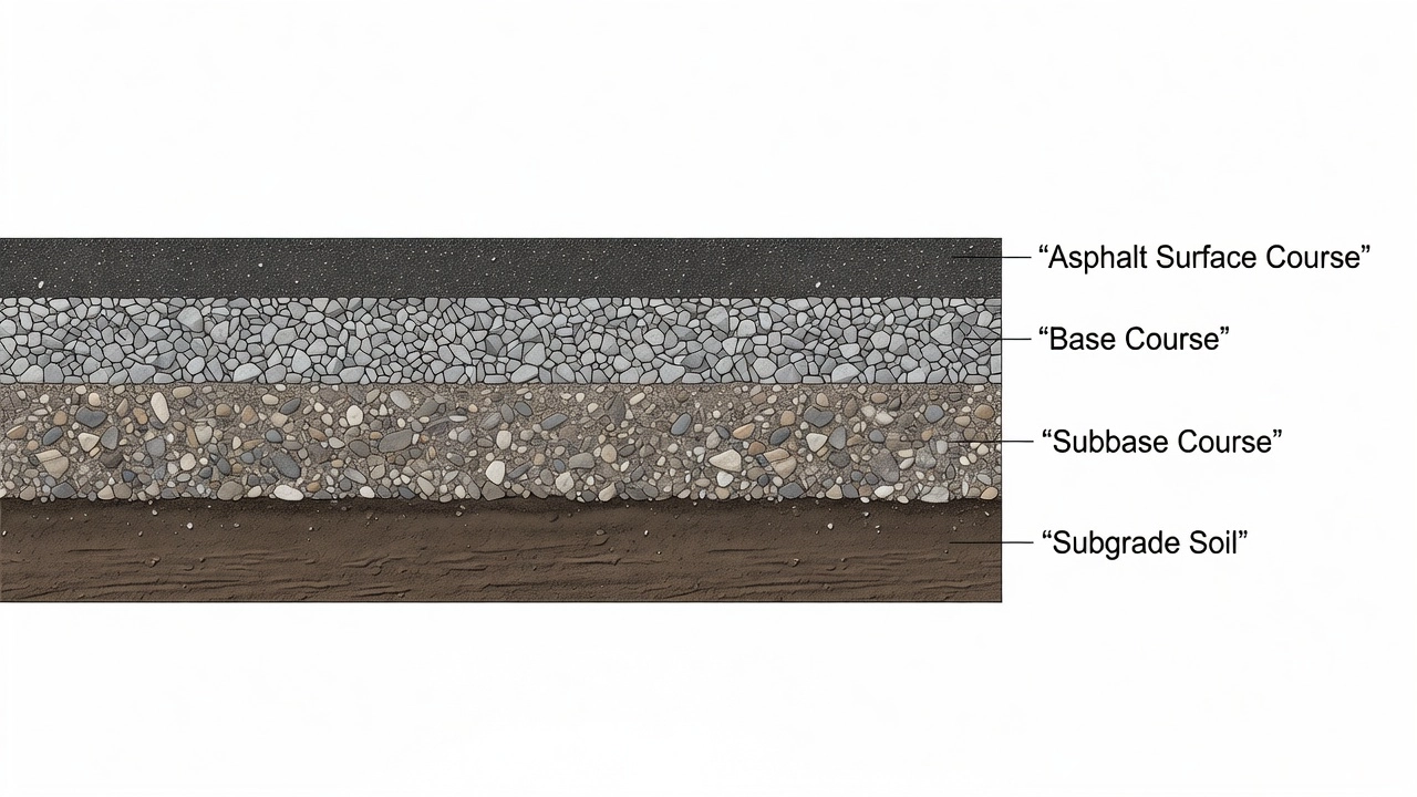
The fundamental objective of pavement thickness design is to determine the structural layer thicknesses — surface course, base course, and subbase course — required to distribute applied traffic loads to the subgrade at stress levels that the subgrade can sustain without excessive deformation or structural failure. This must be achieved across a specified design life, typically 20 years for highways and 20 years for airport pavements, while maintaining acceptable ride quality and structural integrity under the combined effects of traffic loading and environmental conditions.
The pavement structure must simultaneously satisfy two basic performance requirements. First, it must provide adequate structural capacity to support the imposed loads without excessive fatigue cracking, rutting, or faulting. Second, it must furnish a surface that remains firm, stable, smooth, skid-resistant, and free of debris throughout its service life. FAA Advisory Circular 150/5320-6G explicitly states that pavement analysis and design involves the interaction of four equally important components: the subgrade (naturally occurring soil), the paving materials (surface layer, base, and subbase), the characteristics of applied loads (weight, tire pressure, location, and frequency), and climate (high/low temperatures and rainfall). All four must be addressed in any competent thickness design.
The design process is not purely a structural engineering exercise. It requires balancing initial construction cost against long-term maintenance and rehabilitation costs over the analysis period. This cost-effectiveness determination is a required part of FAA pavement design per AC 150/5320-6G. The designer selects the pavement type (flexible asphalt, rigid concrete, or composite), the material specifications for each layer, and the individual layer thicknesses such that the total pavement system provides the required structural capacity at the lowest life-cycle cost.
Empirical Methods
Empirical pavement design methods are based on statistical correlations developed from field performance observations. These methods relate observed pavement behavior to quantifiable inputs using regression equations calibrated to specific test conditions. The two most widely used empirical methods are the AASHTO 1993 Guide for Design of Pavement Structures and the FAA CBR (California Bearing Ratio) method for airport pavements.
AASHTO 1993 Method
The AASHTO 1993 design procedure is the empirical method most extensively used by state highway agencies across the United States, with approximately 80% of states employing it as of FHWA surveys. The method is derived from the AASHO Road Test conducted in Ottawa, Illinois, from 1958 to 1960, where approximately 1,100 test sections were subjected to controlled traffic loading using vehicles with known axle loads and configurations. The field performance data collected during this accelerated two-year test formed the empirical foundation for all subsequent AASHTO design guides.
The basic design equation for flexible pavements in the 1993 AASHTO Guide is:
Where W₁₈ is the predicted number of 18-kip (80 kN) equivalent single axle loads (ESALs), ZR is the standard normal deviate for the selected reliability level, S₀ is the combined standard error of traffic and performance prediction, SN is the Structural Number, ΔPSI is the allowable serviceability loss (difference between initial serviceability index p₀ and terminal serviceability index pₜ), and MR is the subgrade resilient modulus in psi.
The Structural Number (SN) is the central output of the AASHTO 1993 design equation. It is an abstract index representing the overall structural capacity of a flexible pavement and is expressed as:
SN = a₁ × D₁ + a₂ × D₂ × m₂ + a₃ × D₃ × m₃
In this equation, a₁, a₂, and a₃ are structural layer coefficients that represent the relative strength of the surface, base, and subbase materials. Typical values for a₁ (asphalt concrete surface) range from 0.40 to 0.44 for dense-graded asphalt with a resilient modulus of approximately 450,000 psi at 68°F. D₁, D₂, and D₃ are the layer thicknesses in inches. m₂ and m₃ are drainage coefficients for unbound base and subbase layers, ranging from 0.40 for poor drainage (slow-draining layers often saturated) to 1.40 for excellent drainage (quick-draining layers almost never saturated). A standard drainage coefficient of 1.0 represents the original AASHO Road Test condition.
Critical limitations of the AASHTO 1993 method include: the equations were developed based only on the specific pavement materials, roadbed soil, and environment present at the AASHO Road Test site in Illinois; the accelerated two-year testing period does not fully capture long-term environmental effects over a 20+ year design life; and the loads were operating vehicles with identical axle loads rather than mixed traffic. The method requires users to accept several extrapolations: that subgrade support characterization can be extended to other soils, that mixed traffic can be represented through ESALs, that material characterizations apply across different materials through layer coefficients, and that accelerated two-year test results can be extrapolated to 20–50 year design lives.
FAA CBR Method
Prior to the development of FAARFIELD, the FAA used the California Bearing Ratio (CBR) method for flexible airport pavement design, documented in the now-superseded Advisory Circular 150/5320-6D. This empirical method uses the CBR value of the subgrade and base materials to determine required pavement thickness through design curves developed from field performance observations at operational airports.
The relationship is based on the principle that the pavement thickness required to protect the subgrade is inversely related to the subgrade CBR. A weaker subgrade (lower CBR) requires thicker pavement layers to spread the load sufficiently and prevent subgrade failure. The FAA CBR design curves were developed for specific aircraft types and gear configurations, correlating pavement thickness to the number of coverages (the number of times a given point on the pavement is loaded by an aircraft tire during its service life). The curves incorporate empirical relationships derived from full-scale tests conducted at the FAA’s National Airport Pavement Test Facility (NAPTF) in Atlantic City, New Jersey.
The FAA CBR method for flexible pavements uses the following fundamental relationship: the total pavement thickness above a given layer is determined from the subgrade CBR and the traffic expressed in equivalent annual departures of a design aircraft. The method accounts for different aircraft types by converting mixed traffic to equivalent departures of a single design aircraft using equivalency factors. The FAA published separate design curves for each major aircraft type, with thickness requirements decreasing as CBR increases.
Mechanistic-Empirical Methods
Mechanistic-Empirical (M-E) pavement design represents a significant advancement over purely empirical methods by combining mechanistic analysis of pavement responses (stresses, strains, and deflections computed using layered elastic theory or finite element analysis) with empirical transfer functions that relate these computed responses to observed pavement distress such as fatigue cracking and rutting.
MEPDG (AASHTOWare Pavement ME Design)
The Mechanistic-Empirical Pavement Design Guide (MEPDG), implemented through the AASHTOWare Pavement ME Design software, is the most advanced M-E design procedure available for highway pavements. It was developed under NCHRP Project 1-37A and adopted by AASHTO in 2008. Unlike the AASHTO 1993 method which relies on a single empirical equation, the MEPDG uses incremental damage accumulation over the pavement’s design life, processing inputs on a monthly or hourly basis to account for seasonal variations in temperature, moisture, and material properties.
The mechanistic component of the MEPDG computes pavement responses using multi-layer elastic theory (for flexible pavements) or finite element analysis (for rigid pavements). For flexible pavements, the critical response parameters are:
Horizontal tensile strain at the bottom of the asphalt layer (εₜ) — used to predict bottom-up fatigue cracking
Vertical compressive strain at the top of the subgrade (εᵥ) — used to predict structural rutting
Vertical compressive stress within pavement layers — used to predict permanent deformation in unbound materials
These computed strains are input into empirical transfer functions — regression equations that relate the computed mechanistic response to observed field distress. For example, the fatigue cracking transfer function is of the form:
Nf = k₁ × β₁ × (εₜ)^(−k₂ × β₂) × (E)^(−k₃ × β₃)
Where Nf is the number of load repetitions to failure, εₜ is the tensile strain, E is the asphalt modulus, k₁, k₂, k₃ are calibration coefficients, and β₁, β₂, β₃ are local calibration factors. The MEPDG uses two major transfer functions: one for fatigue cracking (both bottom-up and top-down) and one for rutting (permanent deformation). Rigid pavement distress prediction includes slab cracking, joint faulting, and punchouts.
The MEPDG requires significantly more detailed input data than AASHTO 1993. Traffic must be provided as a full load spectrum (axle load distributions by axle type, not just total ESALs). Climate data is input as hourly weather records for the project location, including temperature, precipitation, wind speed, percent sunshine, and relative humidity. The software includes a database of over 800 climate stations across the United States. Material properties must be characterized by their hierarchical input levels: Level 1 (site-specific testing), Level 2 (regional default values with some testing), or Level 3 (national default values).
Transfer Functions
Transfer functions are the empirical bridge between mechanistic pavement response calculations and observed pavement distress. They are developed through calibration against long-term pavement performance data from sources such as the Long-Term Pavement Performance (LTPP) program, the AASHO Road Test, and accelerated pavement testing facilities. The accuracy of any M-E design method depends heavily on how well its transfer functions are calibrated for local conditions.
For flexible pavements, the Asphalt Institute fatigue criterion is one of the most widely used transfer functions: Nf = 0.0796 × (εₜ)^(−3.291) × (E)^(−0.854). The Shell Oil rutting criterion predicts subgrade rutting as: Nd = 1.05 × 10⁻² × (εᵥ)^(−4.484). The MEPDG implements nationally calibrated versions of these functions with additional coefficients for different distress types.
For rigid pavements, transfer functions relate computed slab edge stresses to fatigue life using the PCA fatigue analysis method or the zero-maintenance fatigue criteria. The FAARFIELD rigid pavement design uses a single failure criterion: bottom-up fatigue cracking of the portland cement concrete (PCC) slab, calibrated from tests at the NAPTF.
FAA FAARFIELD Method
The FAA Rigid and Flexible Iterative Elastic Layer Design (FAARFIELD) software is the mandated tool for designing airport pavements under FAA Advisory Circular 150/5320-6G, published June 7, 2021. FAARFIELD replaced the earlier FAA CBR and PCA (Portland Cement Association) design methods and represents the state of the art in airfield pavement thickness design. The software is available at no cost from the FAA Airport Technology Research & Development Branch.
Layered Elastic Analysis
FAARFIELD uses two structural analysis engines depending on pavement type. For flexible pavement design, the software uses LEAF (Layered Elastic Analysis for FAARFIELD), a multi-layer elastic computer program that computes stresses, strains, and deflections within a layered pavement system subjected to aircraft loads. LEAF assumes that each pavement layer is homogeneous, isotropic, and linearly elastic, with material properties defined by elastic modulus (E) and Poisson’s ratio (ν).
For rigid pavement design, FAARFIELD uses the NIKE3D finite element program, a three-dimensional finite element model that accounts for the discrete nature of concrete slabs, load transfer at joints through dowels and aggregate interlock, and the supporting effect of the subgrade and base layers. The NIKE3D model computes edge stresses in the PCC slab — the critical response parameter for rigid pavement fatigue design.
FAARFIELD uses the following allowable modulus values and Poisson’s ratios per AC 150/5320-6G:
Material Layer
Elastic Modulus (psi)
Poisson’s Ratio
Asphalt Concrete Surface (P-401)
200,000 (at 77°F)
0.30
Portland Cement Concrete (P-501)
4,000,000
0.15
Stabilized Base (P-304)
100,000
0.30
Crushed Aggregate Base (P-209)
45,000
0.35
Subbase (P-154)
22,000
0.40
Subgrade (Eₛ)
Variable (from CBR)
0.45
Cumulative Damage Factor (CDF)
The Cumulative Damage Factor (CDF) is the central design criterion in FAARFIELD. The software applies Miner’s hypothesis (Miner’s rule) for cumulative fatigue damage, where the damage from each aircraft pass is calculated as the ratio of applied load repetitions to allowable load repetitions to failure. The CDF is computed as:
CDF = Σ(nᵢ / Nᵢ)
Where nᵢ is the number of applied load repetitions of aircraft type i, and Nᵢ is the allowable number of load repetitions of aircraft type i to produce failure. The design objective is to achieve a CDF of 1.0 or less over the design life. A CDF of 1.0 indicates that 100% of the pavement’s fatigue life has been consumed. The software iteratively adjusts layer thicknesses until the CDF criterion is satisfied.
The aircraft traffic is characterized in FAARFIELD not as ESALs but as coverages — the number of times a given point on the pavement is loaded by an aircraft tire during its service life. The software accounts for the lateral distribution of aircraft traffic across the pavement width (wander), the gear configuration of each aircraft (tire spacing, number of wheels, wheel load), and the pass-to-coverage ratio that relates the total number of aircraft passes to the number of coverages at the most critical point.
FAARFIELD includes a comprehensive built-in aircraft library with over 200 aircraft types, each characterized by gross weight, gear geometry, tire pressure, and wheel configuration. The library includes all commercial transport aircraft (Airbus, Boeing, Embraer, Bombardier, etc.), military aircraft (C-5, C-17, C-130, F-15, F-16, etc.), and general aviation aircraft. Users can also define custom aircraft through the “User Defined Vehicle” feature.
Input Parameters
The quality of any pavement thickness design depends directly on the accuracy and representativeness of its input parameters. All design methods require characterization of traffic loading, subgrade support, material properties, environmental conditions, and reliability requirements.
Traffic
Traffic characterization differs fundamentally between highway and airport pavement design methods. For highway pavements, traffic is expressed as Equivalent Single Axle Loads (ESALs) — the cumulative number of 18,000 lb (80 kN) single axle loads that would cause the same pavement damage as the expected mixed traffic stream. The ESAL concept was developed from the AASHO Road Test and uses Load Equivalency Factors (LEFs) to convert different axle loads and configurations to equivalent 18-kip single axle loads. The AASHTO 1993 method calculates ESALs as:
Where ADT₀ is average daily traffic at the start of the design period, T is the percentage of trucks, Tf is the truck factor (ESALs per truck), G is the traffic growth factor, D is the directional distribution factor, L is the lane distribution factor, and Y is the design period in years.
For airport pavements, FAA methods use annual departures of each aircraft type, pass-to-coverage ratios (P/C), and the gear configuration (number of wheels, wheel spacing, tire pressure). The FAARFIELD software converts annual departures directly to damage contributions using the mechanistic CDF approach — each aircraft in the mixed traffic stream is considered individually with its specific gear geometry and loading.
Subgrade Strength
Subgrade strength is characterized differently across the major design methods:
AASHTO 1993 uses Resilient Modulus (MR) in psi, measured from repeated load triaxial tests (AASHTO T307), estimated from CBR using MR = 1500 × CBR (for fine-grained soils with CBR ≤ 10, subject to significant variation), or backcalculated from FWD deflection data.
AASHTOWare MEPDG uses Resilient Modulus (MR) with seasonal variation (monthly values throughout the year), incorporating the effect of freeze-thaw cycles and moisture content changes on subgrade stiffness.
FAA FAARFIELD uses California Bearing Ratio (CBR) for flexible pavements (converted to modulus using the relationship E = 1500 × CBR) and Modulus of Subgrade Reaction (k) in pci for rigid pavements, determined from plate load tests (ASTM D1196) or estimated from CBR using published correlations.
FAA CBR Method (historical) uses CBR directly with design curves that relate subgrade CBR to required pavement thickness for each aircraft type.
The seasonal variation of subgrade strength is critical in both highway and airfield design. Freeze-thaw cycles in cold regions can reduce subgrade support by 50–70% during spring thaw, while wet-season moisture content increases can lower CBR values by 40% or more in fine-grained subgrade soils. The AASHTO 1993 method accounts for this through a seasonally averaged MR computed by weighting monthly MR values by the relative damage each month. The MEPDG processes monthly or hourly variations directly.
Material Properties
Each pavement layer must be assigned material properties that reflect its structural contribution. For flexible pavements, the key material property is the dynamic modulus (E)* of the asphalt concrete, which is temperature and loading-rate dependent. The AASHTO 1993 method uses a single modulus value at 68°F (approximately 450,000 psi for typical dense-graded asphalt), while the MEPDG uses the full temperature and frequency dependency through a master curve constructed from laboratory testing.
For unbound granular base and subbase materials, the resilient modulus depends on the stress state (bulk stress and deviator stress) and moisture content. The MEPDG models this stress dependency using the k-θ model: Mr = k₁ × θ^(k₂), where θ is the bulk stress and k₁, k₂ are material constants. The AASHTO 1993 method uses a single representative modulus value for each layer.
For rigid pavements, the critical material properties are the PCC modulus of rupture (flexural strength) at 28 days (typically 600–800 psi for airport pavements), the PCC modulus of elasticity (typically 4,000,000 psi), the PCC coefficient of thermal expansion (approximately 5.5 × 10⁻⁶/°F), and the PCC unit weight (typically 150 pcf).
Reliability
The reliability factor accounts for uncertainty in traffic prediction, material variability, construction quality, and environmental effects. In the AASHTO 1993 method, reliability is expressed as a percentage (R) and converted to a standard normal deviate (ZR). Recommended reliability levels range from 50% for low-volume local roads to 99.9% for high-volume urban interstates. The overall standard deviation (S₀) accounts for the combined uncertainty of traffic prediction and pavement performance prediction, typically 0.35–0.50 for flexible pavements and 0.30–0.40 for rigid pavements.
The AASHTO MEPDG incorporates reliability at the distress prediction level rather than in the design equation. A specified reliability level (e.g., 95%) means that only 5% of pavement sections are expected to exceed the design distress threshold at the end of the design life.
FAA FAARFIELD does not incorporate a formal reliability factor in the thickness design algorithm. Instead, the FAA addresses reliability through minimum layer thickness requirements, conservative material property defaults, and mandatory quality control during construction.
Drainage
Drainage is accounted for differently in each design method. The AASHTO 1993 method uses a drainage coefficient (m) applied to unbound base and subbase layers, ranging from 0.40 (poor drainage) to 1.40 (excellent drainage). The coefficient is determined by the quality of drainage (time required to remove water) and the percentage of time the pavement is exposed to near-saturation moisture conditions.
The MEPDG addresses drainage through the pavement moisture environment, where the water table depth, precipitation, and drainage layer characteristics directly affect the pore pressure and effective stress in unbound materials, which in turn influences their resilient modulus.
FAA FAARFIELD and the FAA AC 150/5320-6G require a drainage layer (P-211 or P-212) beneath rigid pavements and recommend subsurface drainage for both flexible and rigid pavements where water infiltration is a concern. The standard minimum thickness for P-211 drainage layer is 4 inches.
Terminal Serviceability
Terminal serviceability (pₜ) is the minimum acceptable level of pavement performance at the end of the design life, quantified by the Present Serviceability Index (PSI) in the AASHTO method. The PSI scale ranges from 5.0 (perfect condition) to 0.0 (impossible to travel), although the practical range for real pavements is approximately 4.5 to 1.5. The PSI is determined from pavement roughness (slope variance), cracking, patching, and rutting measurements using the equation:
Where SV is slope variance (roughness), C is cracking (ft²/1000 ft²), P is patching (ft²/1000 ft²), and RD is average rut depth (inches).
The AASHTO 1993 method defines initial serviceability (p₀) as the PSI immediately after construction, typically 4.2 for flexible pavements and 4.5 for rigid pavements. The terminal serviceability (pₜ) is selected based on road classification: 2.5–3.0 for major highways (interstates, principal arterials), 2.0–2.5 for secondary highways (collectors), and 1.5–2.0 for low-volume roads. The allowable serviceability loss is ΔPSI = p₀ − pₜ, which is partitioned between traffic-induced damage and environmental effects (swelling soils, frost heave) using:
ΔPSI = ΔPSI_TR + ΔPSI_SW + ΔPSI_FH
For airport pavements, FAA methods do not explicitly use PSI as a design input. Instead, performance is defined in terms of the CDF (cumulative damage factor) reaching 1.0 at the end of the design life, which corresponds to the onset of structural distress (fatigue cracking for flexible pavements, slab cracking for rigid pavements).
Overlay Design
Overlay design determines the thickness of additional pavement material (asphalt or concrete) placed over an existing pavement to extend its service life or increase its structural capacity. The design methodology depends on the type of existing pavement (flexible or rigid), the type of overlay (asphalt, concrete, or composite), and the condition of the existing pavement.
AASHTO Overlay Method
The AASHTO 1993 overlay design procedure is based on the concept of structural deficiency: the required overlay thickness is determined by comparing the existing pavement’s structural capacity (SN_eff) to the structural capacity required for future traffic (SN_future). The required overlay structural number (SN_ol) is:
SN_ol = SN_future − SN_eff
The effective structural number (SN_eff) of the existing pavement is determined from the pavement’s condition. For flexible pavements, SN_eff is calculated from the remaining life, which is derived from the Present Serviceability Index (PSI). The remaining life factor (RLF) is applied to the original structural number to obtain SN_eff. Nondestructive testing (FWD) can also be used to backcalculate layer moduli and compute SN_eff directly.
The overlay thickness is then computed by dividing SN_ol by the structural layer coefficient of the overlay material (a_ol), adjusted for bond condition between the existing pavement and the overlay:
D_ol = SN_ol / a_ol
The AASHTO method also provides separate procedures for: asphalt overlay over existing asphalt pavement (flexible on flexible), asphalt overlay over existing concrete pavement (flexible on rigid — requires reflection crack control), and concrete overlay over existing concrete pavement (rigid on rigid — bonded or unbonded).
FAA FAARFIELD Overlay Method
FAARFIELD provides overlay design capabilities for four scenarios, all documented in FAA AC 150/5320-6G and illustrated in Appendix H: asphalt overlay on flexible pavement, concrete overlay on flexible pavement, asphalt overlay on rigid pavement, and unbonded concrete overlay on rigid pavement.
For asphalt overlay on flexible pavement, the existing pavement structure is characterized in FAARFIELD by inputting the existing layer thicknesses and material types. The software evaluates the existing structure against the design traffic using the CDF approach. If the existing structure has CDF > 1.0 for the design traffic, the software iteratively determines the required overlay thickness to achieve CDF ≤ 1.0.
For asphalt overlay on rigid pavement, FAARFIELD models the existing PCC slabs as a high-modulus base layer beneath the new asphalt overlay. The design accounts for reflection cracking potential through minimum overlay thickness requirements — FAA specifies a minimum 5-inch HMA overlay for structural overlays over existing rigid pavement to control reflection cracking.
For unbonded concrete overlay on rigid pavement (sometimes called “PCC on PCC”), FAARFIELD models the existing PCC and the overlay PCC as two separate slabs separated by a bond-breaking interlayer (typically 1 inch of asphalt or geotextile). The design software computes stresses in both slabs using the 3D-FE model and calculates the cumulative fatigue damage in each separately.
Design vs As-Built and Inspection Findings
The relationship between pavement thickness design and as-built conditions — as observed during construction quality assurance and subsequent field inspections — is critical for understanding why pavements perform as they do. Discrepancies between the design assumptions and actual field conditions are the primary cause of premature pavement failure.
Common discrepancies between design and as-built conditions include:
Layer thickness variations: As-built core samples or ground penetrating radar (GPR) surveys frequently reveal that layer thicknesses differ from the design values by 0.5–1.5 inches. The FAA AC 150/5320-6G permits a tolerance of ±0.25 inches for asphalt surface course thickness and ±0.5 inches for base and subbase layers. A 1-inch reduction in asphalt thickness can reduce fatigue life by 30–50%.
Material property variations: The actual in-place modulus of asphalt concrete depends on the achieved density, air void content, binder content, and aggregate gradation. A density 2% below the target (typically 96% of Marshall or Superpave Gmm) can reduce the modulus by 20% and decrease fatigue life by a factor of 2–4. For PCC pavements, a 100 psi reduction in flexural strength (from 700 psi to 600 psi) can reduce allowable load repetitions by 50%.
Subgrade strength variation: The subgrade resilient modulus assumed during design (derived from a limited number of soil samples) may not represent the actual site conditions. Subgrade variability across a project site can easily span a factor of 2 in MR (e.g., from 5,000 psi to 10,000 psi). For a typical flexible pavement designed to MR = 7,500 psi, a localized area with MR = 4,000 psi would require approximately 30% more structural capacity than provided.
Traffic exceeding design: The actual cumulative traffic (ESALs for highways, annual departures for airports) may exceed the design traffic due to higher-than-forecast growth rates, operational changes, or aircraft type substitutions. The FAA requires airport pavement designs to accommodate a 20-year forecast of aircraft operations; actual traffic may deviate substantially from this forecast.
Construction quality issues: Poor compaction, inadequate curing, improper joint construction, and thermal segregation in hot mix asphalt all create localized weaknesses that become critical under load.
Inspection methods to detect design vs as-built discrepancies:
Ground Penetrating Radar (GPR) is specifically addressed in FAA AC 150/5320-6G Appendix E for pavement layer thickness evaluation. The GPR survey transmits electromagnetic pulses into the pavement and measures the reflected signals to determine layer thicknesses. For flexible pavements, the GPR antenna can resolve layer interfaces down to approximately 1-inch resolution using a 1.5 GHz air-coupled antenna or a 2.0 GHz ground-coupled antenna.
The Dynamic Cone Penetrometer (DCP) is addressed in FAA AC 150/5320-6G Appendix D for rapid in-situ evaluation of subgrade and base strength. The DCP measures the penetration resistance of pavement layers and subgrade by dropping a 17.6 lb (8 kg) hammer a distance of 22.6 inches (575 mm). The penetration rate (mm per blow) is correlated to CBR, resilient modulus, and soil classification using established correlations (ASTM D6951).
Nondestructive Testing (NDT) using the Falling Weight Deflectometer (FWD), documented in FAA AC 150/5320-6G Appendix C, measures pavement surface deflections under an impulse load simulating an aircraft wheel. The deflection basin measured by sensors at seven radial distances from the load plate is used to backcalculate layer moduli. Backcalculation compares the measured deflection basin to theoretical deflections from layered elastic analysis for flexible pavements or finite element analysis for rigid pavements, then iteratively adjusts layer moduli to minimize the error between measured and calculated deflections. The backcalculated moduli provide an in-situ assessment of the structural capacity of each layer as built, which can be compared to the design assumptions.
Pavement Remaining Life
Pavement remaining life is the percentage of a pavement’s structural capacity that remains unused at a given point in time, considering the traffic loads already applied and the environmental effects already incurred. It is a key concept for pavement management, rehabilitation planning, and budget allocation.
For AASHTO 1993 design, remaining life is calculated from the Present Serviceability Index (PSI). The relationship between serviceability loss and traffic application follows the same empirical equation used in design. The remaining life factor (RLF) is calculated as:
RLF = (pₜ − p_min) / (p₀ − p_min)
Where pₜ is the current terminal serviceability threshold, p₀ is the initial serviceability (4.2 for flexible), and p_min is the minimum possible PSI (approximately 1.5). For example, if a flexible pavement has a current PSI of 3.0, with p₀ = 4.2 and pₜ = 2.5, the ratio of serviceability already consumed is (4.2 − 3.0) / (4.2 − 2.5) = 0.71, meaning 71% of the serviceability life is consumed and 29% remains. However, this is a serviceability-based measure, not a direct structural measure.
For FAARFIELD design, remaining life is directly expressed in terms of the Cumulative Damage Factor (CDF). The remaining life in percentage is:
Remaining Life (%) = 100 × (1 − CDF_current)
Where CDF_current is the cumulative damage factor calculated for the traffic already applied. For example, after 15 years of a 20-year design, if the CDF consumed is 0.65, the remaining life is 35% (100 × (1 − 0.65)). It is important to note that this assumes future traffic will be the same as forecast. If actual traffic differs from the design forecast, the remaining life must be recalculated.
For evaluation of existing pavements using nondestructive testing (NDT), remaining life is estimated by comparing the backcalculated structural capacity to that required for future traffic. This approach is described in FAA AC 150/5320-6G Chapter 5 (Pavement Structural Evaluation). The Falling Weight Deflectometer (FWD) deflection data is used to backcalculate the effective structural number (SN_eff) for flexible pavements or the effective subgrade k-value and PCC modulus for rigid pavements. The remaining life is then calculated using the original design equations with the effective structural values substituted for the design values.
The FAA structural evaluation procedure, documented in FAA AC 150/5320-6G Section 5.4, provides a life evaluation module within FAARFIELD that calculates the remaining service life of an existing pavement structure based on current traffic and material properties. The evaluation begins by defining the existing pavement structure in the software, then running the “Life Evaluation” function to compute the CDF for a specified traffic level and time period. If the CDF is less than 1.0, the pavement has remaining life; if the CDF equals or exceeds 1.0, structural overlay is required.
Software Tools
Several software tools implement the pavement thickness design methods described above, ranging from simple empirical calculators to comprehensive mechanistic-empirical analysis platforms.
FAARFIELD
FAARFIELD (FAA Rigid and Flexible Iterative Elastic Layer Design), version 2.0 as of AC 150/5320-6G, is the FAA’s official pavement design software for civil airport pavements. It is available for free download from the FAA Airport Technology Research & Development website. FAARFIELD 2.0 includes: flexible pavement design using LEAF layered elastic analysis, rigid pavement design using NIKE3D 3D-FE, overlay design for all four pavement type combinations (flexible on flexible, concrete on flexible, flexible on rigid, unbonded concrete on rigid), life evaluation of existing pavements, an aircraft library with 200+ aircraft types, user-defined vehicle capability for custom aircraft or ground service equipment (GSE), and compaction requirement calculations.
AASHTOWare Pavement ME Design
AASHTOWare Pavement ME Design (formerly known as MEPDG) implements the Mechanistic-Empirical Pavement Design Guide methodology. It is the most sophisticated pavement design software available for highway pavements, providing: full mechanistic-empirical analysis with incremental damage computation, hierarchical input levels (1, 2, and 3), climate modeling using hourly weather data, traffic characterization as full load spectra, distress prediction (fatigue cracking, rutting, thermal cracking, IRI roughness, joint faulting, punchouts), and reliability analysis at the distress prediction level.
PaveXpress
PaveXpress is a free online pavement thickness design tool developed by the National Asphalt Pavement Association (NAPA) and the Asphalt Institute. It implements the AASHTO 1993 design method for flexible and rigid pavements and the AASHTO 1998 supplement for rigid pavements. PaveXpress provides a user-friendly interface suitable for preliminary design work, design verification, and educational purposes. It runs entirely in a web browser without requiring software installation.
WinPAS
WinPAS (Windows Pavement Analysis Software) was the FAA’s predecessor to FAARFIELD, used for airport pavement design under Advisory Circulars 150/5320-6C and 6D. It implemented the FAA CBR method for flexible pavements and the PCA method for rigid pavements. WinPAS has been superseded by FAARFIELD and is no longer supported or maintained.
Backcalculation Software
Several specialized software tools are used for backcalculation of layer moduli from FWD deflection data: ELMOD (Evaluation of Layer Moduli and Overlay Design), MODULUS, EVERCALC, and BISDEF. These tools implement layered elastic theory and optimization algorithms to match measured deflection basins to theoretical deflections by iteratively adjusting layer moduli. The backcalculated moduli are used in pavement evaluation, overlay design, and remaining life estimation per the procedures in FAA AC 150/5320-6G Appendix C.
Empirical methods, such as AASHTO 1993 and the FAA CBR method, are based on statistical correlations developed from field performance observations like the AASHO Road Test (1958–1960). They relate observed pavement performance (serviceability loss) to traffic loads, material properties, and layer thicknesses using regression equations. Mechanistic-empirical (M-E) methods, such as the AASHTOWare Pavement ME Design (MEPDG) and FAA FAARFIELD, compute pavement responses (stresses, strains, and deflections) using layered elastic theory or finite element analysis, then apply transfer functions to predict distress accumulation over time. M-E methods better account for climate, material nonlinearity, and mixed traffic, but require more detailed input data.
The Structural Number (SN) is an abstract index representing the overall structural capacity of a flexible pavement. It is calculated as SN = a₁D₁ + a₂D₂m₂ + a₃D₃m₃, where aᵢ are structural layer coefficients reflecting material strength, Dᵢ are layer thicknesses in inches, and mᵢ are drainage coefficients for unbound layers. The AASHTO 1993 design equation relates SN to traffic (ESALs), subgrade resilient modulus (Mr), serviceability loss (ΔPSI), and reliability parameters (ZR, S₀). The required SN is first computed from these inputs, then decomposed into individual layer thicknesses.
FAA FAARFIELD (Federal Aviation Administration Rigid and Flexible Iterative Elastic Layer Design) is the mandatory software for designing airport pavements under FAA Advisory Circular 150/5320-6G. It uses layered elastic analysis (LEAF) for flexible pavements and 3D finite element analysis (NIKE3D) for rigid pavements. The design is based on the Cumulative Damage Factor (CDF) concept — Miner's rule is applied to sum fatigue damage from each aircraft pass. The software iteratively adjusts layer thicknesses until CDF ≤ 1.0 for the design life. FAARFIELD includes a built-in aircraft library with gear geometry, tire pressure, and load data for over 200 aircraft types.
Pavement inspection findings often reveal discrepancies between design assumptions and as-built conditions. Common deviations include differences in layer thickness (thinner or thicker than specified), variations in material properties (modulus, density, air voids), subgrade strength weaker than assumed during design, and actual traffic loads exceeding design traffic. Understanding the original design method helps inspectors evaluate whether observed distress results from construction deficiencies, higher-than-expected loading, environmental factors, or inadequate design assumptions. This knowledge guides appropriate rehabilitation strategies such as overlays or reconstruction.
Pavement remaining life is the percentage of a pavement's structural capacity that remains unused at a given point in time. For AASHTO design, remaining life is calculated from the Present Serviceability Index (PSI) using the ratio (pₜ − pₜ₋ₘᵢₙ) / (p₀ − pₜ₋ₘᵢₙ). For FAA FAARFIELD, remaining life is expressed as 100 × (1 − CDF) where CDF is the cumulative damage factor consumed. A CDF of 0.75 means 75% of the pavement's fatigue life has been used, leaving 25% remaining. Nondestructive testing with Falling Weight Deflectometer (FWD) can be used to backcalculate layer moduli and estimate remaining life using pavement evaluation software.
Need Pavement Evaluation Support?
Our team provides expert pavement inspection, structural evaluation, and remaining life analysis for airport and highway pavements. We help bridge the gap between design assumptions and field performance.
Pavement design life is the planned duration for which a pavement is engineered to serve before requiring major rehabilitation or reconstruction. For airport pa...
The subbase is an optional granular or stabilized layer placed between the subgrade and base course, providing additional load distribution, drainage, frost pro...
The subgrade is the prepared and compacted native soil or improved earth that forms the foundation of a pavement structure. Subgrade strength and uniformity dir...
23 min read
Pavement design
Construction
+3
Cookie Consent We use cookies to enhance your browsing experience and analyze our traffic. See our privacy policy.