Tie bars are deformed steel bars placed across longitudinal joints in concrete pavement to prevent lane separation and hold adjacent slabs tightly together. Unlike dowel bars, tie bars do not transfer loads but prevent joint opening. Covers design, placement, and the consequences of tie bar failure for pavement integrity.
Tie Bars in Concrete Pavement Longitudinal Joints
Definition and Function
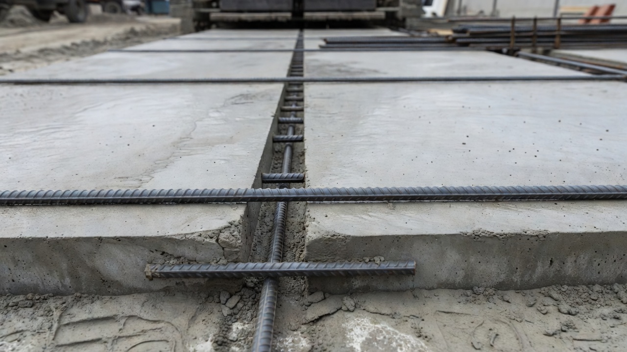
A tie bar is a deformed steel reinforcing bar installed transversely across a longitudinal joint in Portland cement concrete (PCC) pavement to prevent the adjacent slabs from separating over time. Unlike smooth dowel bars used at transverse contraction joints, tie bars feature surface deformations — ribs or lugs — that create a strong mechanical interlock with the surrounding concrete. This bond resists the tensile forces that would otherwise cause the longitudinal joint to widen progressively under the effects of thermal contraction, drying shrinkage, and repeated traffic loading.
The fundamental engineering purpose of a tie bar is to maintain a tight longitudinal joint throughout the service life of the pavement. Longitudinal joints are introduced in concrete pavements to relieve curling and warping stresses caused by temperature and moisture gradients through the slab thickness, and to control longitudinal cracking by dividing the pavement into manageable lane-width panels. Without tie bars, these joints would gradually open as the concrete slabs contract, creating gaps that permit water infiltration, compromise load transfer efficiency, and eventually lead to structural distresses including pumping, faulting, and corner breaks.
Tie bars perform their function through two distinct mechanisms: first, the mechanical bond between the deformed bar surface and the hardened concrete transfers tensile stress from the slab into the steel bar; second, the tensile capacity of the steel bar itself resists elongation, keeping the two slab edges drawn together. The steel area required is calculated based on the subgrade drag theory — the force needed to drag a concrete slab across its supporting layer without yielding the tie bar steel or pulling the bar out of the concrete. This dragging force is a function of the slab weight, the coefficient of friction between slab and base, and the distance from the joint to the nearest free edge.
Tie bars are not load transfer devices. Their contribution to vertical load transfer across longitudinal joints is incidental and minimal — typically in the range of 10 to 20 percent load transfer efficiency (LTE), compared to 85 to 95 percent LTE achievable with properly designed dowel bars. The primary mechanism for load transfer at tied longitudinal joints is aggregate interlock, which remains effective only as long as the joint remains tight. Once a joint opens beyond approximately 1.0 to 1.5 mm due to tie bar failure or inadequate design, aggregate interlock deteriorates rapidly and the pavement begins a cascade toward structural failure.
The distinction between tie bars and dowel bars represents one of the most critical specification decisions in concrete pavement construction. The two bar types are not interchangeable, and using a smooth dowel bar where a deformed tie bar is required — or vice versa — leads to predictable pavement failure. A smooth bar placed in a longitudinal joint cannot develop sufficient bond to resist tensile separation forces, and the joint will open. Conversely, a deformed tie bar placed in a transverse contraction joint will lock the joint shut, preventing thermal movement and generating restraint stresses that produce random transverse cracking across the slab, often within the first year of service.
Tie Bar vs Dowel Bar Differences
The confusion between tie bars and dowel bars persists throughout the construction industry despite their fundamentally different functions, geometries, and placement requirements. Understanding the eight principal differences between these two bar types is essential for specification writers, resident engineers, inspectors, and paving contractors.
Primary Function. Dowel bars transfer vertical wheel loads from one slab to the adjacent slab across a transverse contraction joint, maintaining slab alignment and preventing differential vertical displacement — faulting — at the joint. Tie bars resist horizontal tensile forces at longitudinal joints, preventing lane separation. This functional distinction is absolute: a dowel bar transfers load but permits joint movement; a tie bar prevents joint movement but does not transfer load.
Joint Type and Orientation. Dowel bars are placed across transverse contraction joints, oriented perpendicular to the direction of traffic flow and parallel to the direction of paving. Tie bars are placed across longitudinal joints — both longitudinal contraction joints (saw-cut in monolithic placements) and longitudinal construction joints (cold joints between adjacent lane placements) — oriented parallel to traffic flow and perpendicular to the paving direction.
Surface Geometry. Dowel bars are smooth, plain round bars with no surface deformations. The smooth surface is essential to permit the slabs to slide relative to the bar as they expand and contract thermally. Tie bars are deformed bars conforming to ASTM A615, with surface ribs or lugs that create a positive mechanical interlock with the surrounding concrete. This deformation pattern is identical to standard reinforcing bar (rebar) used in structural concrete.
Bond Condition. Dowel bars are bonded to the concrete on only one side of the joint; the other half is coated with a bond-breaking compound, encased in a plastic sleeve, or simply left ungreased to permit free axial movement. This deliberate debonding allows the joint to open and close with temperature changes without generating restraint stresses. Tie bars are fully bonded on both sides of the joint along their entire embedment length, using the full development length of the bar to transfer tensile force from concrete to steel.
Load Transfer Capability. Dowel bars provide 85 to 95 percent load transfer efficiency when properly designed, sized, and aligned. Their shear capacity — typically 40 to 50 kN per bar for standard 32 mm diameter dowels — is the primary design parameter. Tie bars provide negligible vertical load transfer; their contribution to LTE is typically less than 20 percent, and it degrades rapidly as the joint begins to open.
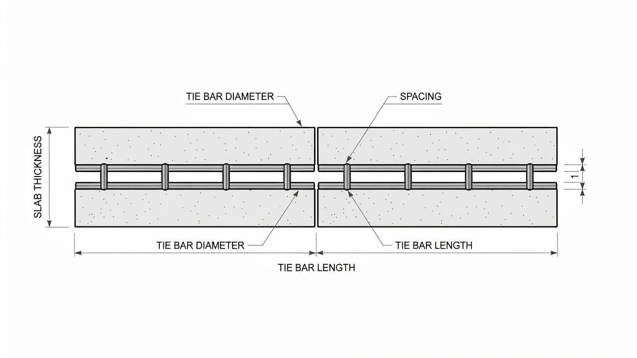
Material Grade and Diameter. Dowel bars are typically manufactured from ASTM A615 Grade 60 plain round steel, in diameters ranging from 25 mm (1 inch) to 38 mm (1.5 inches). Tie bars are typically Grade 40 or Grade 60 deformed bars in smaller diameters — No. 4 (12.7 mm), No. 5 (15.9 mm), or No. 6 (19.1 mm) — because the tensile force required to restrain slab contraction is substantially less than the shear force required for load transfer.
Length and Spacing. Dowel bars are relatively short — 350 to 500 mm (14 to 20 inches) — and closely spaced at 300 mm (12 inches) center-to-center to provide continuous load transfer along the joint. Tie bars are longer — 610 to 910 mm (24 to 36 inches) for highway pavements, with embedment lengths on each side of the joint sufficient to develop the full tensile capacity of the bar — and spaced more widely at 610 to 1,220 mm (24 to 48 inches) center-to-center because they do not need to transfer load at every point along the joint.
Corrosion Protection. Both bar types are susceptible to corrosion when exposed to moisture and deicing chemicals penetrating through unsealed joints. Epoxy coating per ASTM A775 is standard for both dowel bars and tie bars in most highway and airport applications. However, the consequences of corrosion differ: a corroded dowel bar loses section gradually and may continue to provide partial load transfer for years; a corroded tie bar that ruptures in tension causes immediate and irreversible joint separation.
The following table summarizes the key dimensional and functional differences:
Parameter
Tie Bar
Dowel Bar
Primary function
Prevent slab separation
Transfer wheel loads
Joint type
Longitudinal joints
Transverse contraction joints
Surface
Deformed (ribbed per ASTM A615)
Smooth (plain round)
Bond to concrete
Fully bonded both sides
Bonded one side, debonded other
Load transfer
Minimal (<20% LTE)
Primary purpose (85–95% LTE)
Typical diameter
12.7–19.1 mm (No. 4–No. 6)
25–38 mm (1–1.5 in.)
Typical length
610–910 mm (24–36 in.)
350–500 mm (14–20 in.)
Typical spacing
610–1,220 mm (24–48 in.) c/c
300 mm (12 in.) c/c
Steel grade
Grade 40 or Grade 60
Grade 60
Coating
Epoxy per ASTM A775
Epoxy per ASTM A775/A1078
Design: Diameter, Length, and Spacing
Tie bar design is governed by the principle of subgrade drag theory (SDT), which calculates the tensile force required to drag a concrete slab across its supporting layer as the slab contracts due to temperature drop and drying shrinkage. The SDT approach determines the quantity of steel needed to resist this dragging force without yielding the steel or pulling the bar out of the concrete. The fundamental equation relates the required steel area to the slab weight, the friction coefficient at the slab-base interface, and the distance from the longitudinal joint to the nearest free edge or untied joint.
The subgrade drag force (F) acting on a slab of width W, length L, and thickness h is calculated as:
F = γ × h × W × L × f
Where γ is the unit weight of concrete (approximately 23.6 kN/m³ or 150 pcf), and f is the coefficient of friction between the concrete slab and the underlying base layer. Published friction coefficients range from 0.5 to 1.0 for granular bases, 1.0 to 1.5 for cement-treated bases, and 1.5 to 2.0 for asphalt-treated or lean concrete bases. Higher friction coefficients require proportionally more tie bar steel.
The required steel area (As) per unit length of longitudinal joint is then:
As = F / (fs × Ls)
Where fs is the allowable tensile stress in the tie bar steel — typically 0.67 × yield strength for Grade 40 (186 MPa or 27 ksi) or Grade 60 (276 MPa or 40 ksi) steel — and Ls is the length of the longitudinal joint being considered.
Standard Tie Bar Dimensions for Highway Pavements. The American Association of State Highway and Transportation Officials (AASHTO) 1993 Guide for Design of Pavement Structures provides design charts that relate slab thickness, lane width, and base friction to recommended tie bar size and spacing. For a typical 250 mm (10 inch) thick JPCP slab, 3.7 m (12 ft) wide lane, on a granular base, the standard design yields:
No. 4 bars (12.7 mm diameter): 760 mm (30 in.) long, spaced at 760 mm (30 in.) center-to-center
No. 5 bars (15.9 mm diameter): 760 mm (30 in.) long, spaced at 1,070 mm (42 in.) center-to-center
For pavements on stabilized bases with higher friction coefficients, closer spacing or larger bar diameters are required. Many state departments of transportation have adopted standard tie bar designs based on slab thickness categories: No. 4 bars for slabs less than 200 mm (8 inches) thick, No. 5 bars for slabs 200 to 250 mm (8 to 10 inches) thick, and No. 6 bars for slabs greater than 250 mm (10 inches), all at 760 mm (30 inch) spacing with 760 mm (30 inch) embedment lengths.
Limitations of Subgrade Drag Theory. Research conducted by Applied Research Associates for the American Concrete Pavement Association (ACPA) in 2009 identified significant limitations in the traditional SDT approach. The SDT method does not account for the effects of temperature drop magnitude, concrete drying shrinkage strain, slab-base interface friction variability, or the stress concentration at the tie bar-concrete interface. This can result in under-designed tie bar systems when environmental conditions are severe. The research led to a mechanistic-empirical (M-E) tie bar design method that uses finite element modeling (ISLAB2005) to compute tie bar stresses under combined thermal, shrinkage, and mechanical loading, providing more accurate design solutions for specific project conditions.
The M-E approach demonstrated that tie bar stresses can be 10 to 20 times higher than the stresses in transverse steel reinforcement under identical environmental conditions, confirming that tie bar design warrants significantly more attention than it has historically received in pavement design practice.
Placement and Embedment
Correct placement of tie bars is as critical as correct design. Research by the Colorado Department of Transportation (CDOT) in 2011 revealed that tie bar misalignment or misplacement was directly correlated with poor longitudinal joint performance. Field measurements showed that joints where tie bars had adequate embedment length on both sides — even when the bars were slightly misaligned angularly — remained tight. Joints where tie bars had been placed with insufficient embedment on one or both sides exhibited openings comparable to untied slabs, effectively negating the purpose of the tie bar system entirely.
Embedment Depth. Tie bars must be placed at the mid-depth of the concrete slab to resist tensile forces without creating eccentric moments that could induce slab warping. For a 250 mm (10 inch) thick slab, this means placement at 125 mm (5 inches) from the surface. Tolerance for vertical placement is typically ±25 mm (±1 inch). Bars placed too close to the surface have reduced concrete cover and are more susceptible to corrosion; bars placed too deep provide less effective restraint against surface-opening tensile stresses.
Embedment Length. The embedment length on each side of the joint must be sufficient to develop the full tensile capacity of the bar through bond with the concrete. Per ACI 318 and AASHTO LRFD provisions, the development length for a No. 4 Grade 60 deformed bar in 28 MPa (4,000 psi) concrete is approximately 380 mm (15 inches). Standard tie bar lengths of 760 mm (30 inches) provide approximately 380 mm of embedment on each side, which is adequate for full bond development. Shorter embedment lengths result in bond failure — the bar pulls out of the concrete — before the steel reaches its yield stress, wasting the tensile capacity of the bar.
Alignment Tolerance. Tie bars must be placed perpendicular to the longitudinal joint within a tolerance of ±15 degrees in both horizontal and vertical planes. Bars placed at angles greater than 15 degrees from perpendicular introduce a vector component that reduces the effective restraining force and may create localized stress concentrations in the concrete at the bar-concrete interface. Modern mechanical tie bar inserters mounted on slipform pavers can achieve placement tolerances of ±5 degrees when properly calibrated.
Installation Methods. Three primary methods are used for installing tie bars at longitudinal construction joints:
Mechanical Insertion. Vibratory or pneumatic inserters mounted on the side of the slipform paver push single-piece tie bars horizontally into the fresh concrete immediately behind the paver’s side form. This is the most common method for production paving and achieves high productivity. Critical quality-control checks include verifying insertion depth (mid-depth of slab), confirming perpendicular alignment, and ensuring that the exposed half of the bar is not disturbed by finishing operations.
Drill and Epoxy Grout. For longitudinal construction joints where mechanical insertion is impractical — such as at transverse construction joints, nighttime headers, or in confined areas — holes are drilled into the hardened concrete face and single-piece tie bars are set in epoxy grout. The drilled hole diameter must be 4 to 6 mm larger than the bar diameter, the hole must be cleaned of all dust and debris, and the epoxy must completely fill the annulus. This method provides bond strengths equivalent to cast-in-place embedment when properly executed.
Multiple-Piece Tie Bars. Two-piece or three-piece tie bar assemblies use a threaded coupler or mechanical splice to connect bar segments installed from each side of the joint. This eliminates the protruding bars that can interfere with adjacent lane paving operations and is specified by several state DOTs as the preferred method. The coupling device must develop the full tensile strength of the bar.
Post-Placement Protection. For mechanically inserted tie bars, the protruding half of the bar is exposed to the elements and construction traffic until the adjacent lane is paved. Plastic protective sleeves (commonly yellow or orange) are placed over the exposed bars to prevent curing compound from coating the bar surface — which would compromise bond development — and to protect construction workers from impalement hazards. The sleeves are removed immediately before the adjacent lane concrete is placed.
Prohibition on Field Bending. Past practice allowed tie bars to be bent down during construction and straightened after the concrete set. This practice is now prohibited by TxDOT, FHWA, and most state agencies. Field bending and subsequent straightening cold-works the steel, causing embrittlement and potential fracture at the bend point. ACI 318 explicitly limits field bending of reinforcing bars, and tie bars that will be subjected to sustained tensile stress are particularly vulnerable to failure at cold-worked locations.
Consequences of Tie Bar Failure
Tie bar failure initiates a predictable cascade of pavement distresses that progress from cosmetic to structural, ultimately requiring full-depth slab replacement or complete pavement reconstruction. Understanding this failure progression is essential for pavement inspectors and maintenance engineers who must assess the severity of longitudinal joint distress and determine appropriate rehabilitation interventions.
Stage 1: Joint Opening. The first and most visible sign of tie bar failure is progressive widening of the longitudinal joint. Joints that are functioning correctly remain at widths of less than 1.0 mm throughout the pavement life. When tie bars yield, rupture, or lose bond, thermal contraction during cold weather opens the joint, and the joint does not fully close when temperatures rise. Joint openings of 3 to 6 mm are classified as moderate distress; openings exceeding 6 mm (0.25 inch) are severe. The CDOT field study documented cases where joint openings reached 25 mm (1 inch) and, in one extreme case, 100 mm (4 inches).
Stage 2: Loss of Aggregate Interlock and Load Transfer. Longitudinal joints rely on aggregate interlock — the mechanical keying of aggregate particles across the joint face — for vertical load transfer. Aggregate interlock is effective only when the joint opening is less than approximately 1.0 to 1.5 mm. As the joint widens beyond this threshold, interlock deteriorates rapidly, and load transfer efficiency drops below 40 percent. Wheels traveling near the joint edge produce high deflections and stresses in the unloaded slab, accelerating fatigue damage.
Stage 3: Water Infiltration and Subgrade Erosion. An open longitudinal joint provides a direct pathway for surface water to penetrate the pavement structure. Water infiltration saturates the subbase and subgrade, reducing their stiffness and load-carrying capacity. Under repeated heavy traffic loading, pore water pressure in the saturated foundation materials causes pumping — the forceful ejection of water and fine subgrade particles through the joint. Pumping erodes the subgrade support beneath the slab edges, creating voids and increasing the unsupported slab length.
Stage 4: Faulting. With subgrade support eroded and load transfer compromised, one slab edge begins to settle relative to the adjacent slab under repeated traffic loads. This differential vertical displacement — faulting — creates a step at the longitudinal joint that can reach 6 to 12 mm or more. Faulted longitudinal joints create ride quality problems, impact loading from vehicle suspensions, and water ponding that accelerates further deterioration.
Stage 5: Longitudinal Cracking. The combination of reduced support, increased edge stresses, and the concentration of tensile stress at the deteriorated joint triggers longitudinal cracking in the adjacent slabs. These cracks typically occur 300 to 600 mm (12 to 24 inches) from the joint and run parallel to it. Once a longitudinal crack develops through the full slab thickness, the slab segment between the crack and the joint loses structural continuity, and the pavement enters a terminal state of deterioration that requires slab replacement.
Stage 6: Corner Breaks and Slab Fragmentation. The final stage involves the intersection of longitudinal cracks with transverse joints, producing corner breaks. These triangular slab fragments rock under traffic, accelerate pumping, and eventually disintegrate into loose chunks that create Foreign Object Debris (FOD) hazards — a critical concern on airport pavements. At this stage, partial-depth repairs are no longer effective, and full-depth slab replacement is required.
Causes of Tie Bar Failure. The CDOT study and FHWA investigation identified four primary causes of tie bar failure. Corrosion-induced rupture is the most common, where deicing chemicals and moisture penetrate the joint, corrode the tie bar, reduce its cross-sectional area, and cause tensile rupture under thermal contraction stresses. The ASCE Journal of Performance of Constructed Facilities documented cases where corroded tie bars failed in shear, resulting in LTE below 40 percent at longitudinal construction joints. Improper placement — bars installed with inadequate embedment length, at incorrect depth, or at excessive angles — was identified by the CDOT study as the leading cause of premature joint opening in relatively young pavements. Inadequate design — using tie bars that are too small, too short, or too widely spaced for the actual base friction conditions — produces slow, progressive joint opening over 10 to 15 years. Field bending damage — cold-working of the steel during bending and straightening — creates a weakened section that may rupture years after construction.
Tie Bar Corrosion
Corrosion of tie bars represents the single most significant long-term threat to longitudinal joint integrity in concrete pavements, particularly in regions where deicing chemicals are used and in coastal airport environments exposed to salt spray. The corrosion mechanism, protective measures, and consequences of corrosion-induced failure are distinct from those affecting other embedded steel elements in pavement structures.
Corrosion Mechanism. Tie bar corrosion is almost exclusively chloride-induced, driven by the penetration of deicing salt solutions (sodium chloride, calcium chloride, magnesium chloride) or seawater through unsealed or poorly sealed longitudinal joints. The chloride ions depassivate the protective alkaline film that naturally forms on steel surfaces in sound concrete (pH > 12.5). Once the chloride concentration at the bar surface exceeds the corrosion threshold — typically 0.2 to 0.4 percent chloride by weight of cement, or approximately 0.6 kg/m³ of concrete — active corrosion initiates.
The corrosion process is electrochemical: anodic regions on the bar surface dissolve iron (Fe → Fe²⁺ + 2e⁻), while cathodic regions consume oxygen and water (O₂ + 2H₂O + 4e⁻ → 4OH⁻). The corrosion products — iron oxides and hydroxides — occupy a volume two to six times greater than the original steel, generating expansive pressures that can crack the surrounding concrete. However, unlike corrosion of transverse reinforcement, which primarily causes concrete spalling, tie bar corrosion is most dangerous because it directly reduces the steel cross-section and, consequently, the tensile load-carrying capacity of the bar.
Corrosion Rate Factors. The rate of tie bar corrosion depends on concrete permeability, moisture availability, oxygen supply, temperature, and chloride concentration. Concrete with a low water-cement ratio (≤0.45) and adequate cover provides significantly better corrosion protection. However, tie bars at longitudinal joints are inherently more vulnerable than other embedded steel because the joint itself is a discontinuity in the concrete — even a well-sealed joint provides less protection than monolithic concrete cover. Once the joint sealant deteriorates after 5 to 8 years of service, chlorides have direct access to the bar.
Epoxy Coating. The primary defense against tie bar corrosion is epoxy coating per ASTM A775/A775M — Standard Specification for Epoxy-Coated Steel Reinforcing Bars. The fusion-bonded epoxy coating provides a dielectric barrier that electrically isolates the steel from the surrounding concrete and prevents chloride ion contact. Coating thickness is typically 175 to 300 μm (7 to 12 mils). Critical quality requirements include:
Holiday detection: The coated bar must be tested for pinholes and discontinuities (holidays) using a high-voltage detector. ASTM A775 permits a maximum of 3 holidays per meter of bar length before repair, and any bar with more than the allowable holidays must be rejected or recoated. Holidays are repaired using a compatible liquid epoxy patching material.
Abrasion resistance: The coating must withstand handling, placement, and concrete consolidation without damage. A minimum coating thickness after abrasion testing ensures durability.
Flexibility: The coating must not crack or debond when the bar is bent, ensuring that any field bending (within ACI 318 limits) does not compromise protection.
Adhesion: The coating must bond to the steel with sufficient strength to prevent underfilm corrosion migration from holidays.
Alternative Corrosion Protection. For severely aggressive environments — coastal airports, runways subject to heavy deicing chemical application, and pavements in marine exposure zones — higher levels of corrosion protection may be specified. These include stainless steel tie bars (ASTM A955, UNS S31653 or S31803 duplex stainless), hot-dip galvanized bars per ASTM A767, or MMFX/ChromX high-chromium steel (ASTM A1035). Stainless steel bars eliminate the corrosion concern entirely but at a cost 6 to 8 times that of epoxy-coated carbon steel. ChromX Grade 4000 or 9000 bars, with 8 to 9 percent chromium content, provide corrosion resistance intermediate between epoxy-coated carbon steel and stainless steel at a moderate cost premium.
Field Performance of Epoxy-Coated Tie Bars. Long-term studies by the Epoxy Interest Group and FHWA have demonstrated that properly manufactured, handled, and installed epoxy-coated tie bars can provide 30 to 40 years of corrosion-free service even in deicing salt environments. However, field performance is highly sensitive to construction quality. Bars that are gouged during handling, have unrepaired holidays, or are placed with damaged coating at the joint face will corrode at the damage location, potentially leading to premature rupture. The most critical location for coating integrity is precisely at the joint plane, where exposure to moisture and chlorides is most direct.
Inspection and Detection
Assessing the condition of tie bars embedded in hardened concrete requires specialized non-destructive testing (NDT) techniques because the bars are inaccessible for direct visual inspection. The inspection objectives are to determine: (1) whether tie bars are present and correctly spaced, (2) whether they are adequately embedded on both sides of the joint, (3) whether they remain intact or have ruptured, and (4) the extent of any corrosion section loss. The combination of ground penetrating radar, visual joint survey, and mechanical testing provides a comprehensive condition assessment.
Ground Penetrating Radar (GPR). GPR is the primary NDT tool for detecting and mapping tie bars in concrete pavement. The technique transmits high-frequency electromagnetic pulses (typically 1.0 to 2.6 GHz for concrete pavement applications) into the pavement and records reflections from embedded objects and layer interfaces. Steel bars produce strong hyperbolic reflections — characteristic inverted U-shaped signatures in radargrams — because of the high dielectric contrast between steel (essentially a perfect reflector) and concrete (dielectric constant approximately 6 to 12).
GPR inspection of tie bars can determine:
Presence and location: Tie bars appear as regularly spaced hyperbolic reflections along longitudinal joints. Missing bars, irregular spacing, and bars that terminate short of the joint are detectable.
Embedment depth: The two-way travel time of the reflection from the bar surface indicates the depth below the pavement surface. Modern GPR systems with calibrated velocity models can determine embedment depth within ±10 mm accuracy.
Bar continuity: A continuous hyperbolic reflection across the joint indicates an intact bar. A truncated or absent reflection on one side may indicate bar rupture or pullout. Research published in the International Journal of Pavement Engineering (2023) demonstrated that deep learning-based analysis of GPR data can detect tie bar anomalies with over 90 percent accuracy.
The FAA Advisory Circular 150/5320-6G, Appendix E, provides guidance on GPR applications for airport pavement evaluation, including detection of embedded steel, voids, and layer thicknesses.
Visual Joint Survey. A systematic visual survey of longitudinal joints documents joint opening width, joint spalling, faulting, and staining patterns that indicate water movement. Joint opening is measured using a calibrated crack comparator or wedge gauge at regular intervals (typically every 15 m or 50 ft) and at each transverse joint intersection. Joint openings are recorded separately for summer and winter conditions, as thermal effects can produce seasonal width variations of 2 to 4 mm even in properly tied joints.
The following joint condition classification is used by FHWA and many state DOTs:
Condition
Joint Opening
Load Transfer
Action Required
Good
< 1.5 mm
> 70% LTE
Routine monitoring
Fair
1.5–6 mm
50–70% LTE
Investigate cause, plan repairs
Poor
6–12 mm
30–50% LTE
Schedule rehabilitation
Failed
> 12 mm
< 30% LTE
Immediate repair or slab replacement
Falling Weight Deflectometer (FWD). The FWD applies an impulse load to the pavement surface and measures the deflection response at multiple sensors. By placing the load plate on one side of a longitudinal joint and measuring deflections on both sides, the load transfer efficiency (LTE) across the joint can be calculated as:
LTE = (δunloaded / δloaded) × 100%
Where δunloaded is the deflection of the unloaded slab at the joint and δloaded is the deflection of the loaded slab at the joint. An LTE above 70 percent indicates adequate load transfer and, by inference, a tight joint with functional tie bars. An LTE below 50 percent is strongly correlated with tie bar failure and joint opening.
Direct Mechanical Testing. In cases where tie bar condition is uncertain after GPR and FWD evaluation, a limited number of bars can be exposed by coring or saw-cutting for direct examination. This destructive technique is used selectively — typically 3 to 5 locations per kilometer of distressed joint — and the cores are examined for bar section loss, corrosion pitting depth, coating condition, and evidence of bar rupture or pullout. The results of direct examination calibrate the NDT findings and support decisions on the extent of required repairs.
Tie Bars in Airport Concrete Pavements
Airport concrete pavements impose requirements on tie bars that exceed typical highway practice in several important respects. The combination of heavier wheel loads, wider slab panels, stricter surface-tolerance requirements, and the critical safety consequences of pavement distress means that tie bar design, specification, and inspection for airfield pavements are addressed in separate regulatory documents with more conservative requirements.
FAA Requirements. The FAA Advisory Circular 150/5320-6G, “Airport Pavement Design and Evaluation” (June 2021), provides mandatory specifications for tie bars in rigid airport pavements constructed under FAA grant assurance programs. The FAA specifies that deformed tie bars must conform to the requirements of Item P-501 — Portland Cement Concrete Pavement, which references ASTM A615 for bar material and ASTM A775 for epoxy coating.
The FAA’s dimensional requirements for tie bars in longitudinal contraction joints (Section 3.14.10 of AC 150/5320-6G) are:
Slab Thickness
Bar Diameter
Bar Length
Spacing
≤ 150 mm (6 in.)
No. 4 (12.7 mm)
510 mm (20 in.)
760 mm (30 in.)
150–225 mm (6–9 in.)
No. 5 (15.9 mm)
660 mm (26 in.)
760 mm (30 in.)
> 225 mm (9 in.)
No. 5 or No. 6
760 mm (30 in.)
760 mm (30 in.)
For longitudinal construction joints, the FAA requires the same tie bar dimensions but with specific provisions for the joint face condition and concrete consolidation around the bars. The longitudinal joint spacing in FAA rigid pavement design is standardized at 3.75 m (12.5 ft) for runway and taxiway lanes, with tied longitudinal joints between all adjacent paving lanes.
Tie Bar Spacing in Wide Panels. For airport pavements with slabs wider than 3.75 m (12.5 ft) — such as wide-body aircraft parking positions, hangar access pavements, or military airfield pavements — the FAA requires a technical analysis to determine appropriate tie bar requirements. The analysis must consider the increased subgrade drag force acting over the wider slab width, which may necessitate closer tie bar spacing, larger bar diameters, or both. FAARFIELD, the FAA’s pavement design software, can be used to evaluate the structural response of wide panels and determine tie bar requirements.
ICAO Standards.ICAO Annex 14 — Aerodromes, Volume I, references the need for longitudinal joints in rigid pavements to be “adequately tied” without specifying detailed dimensions. The detailed guidance is contained in ICAO Doc 9157 — Aerodrome Design Manual, Part 3 — Pavements, which recommends that longitudinal joints be designed with tie bars to prevent separation under the effects of aircraft loading, thermal contraction, and drying shrinkage. ICAO guidance aligns with FAA practice: deformed bars at mid-depth, spaced at intervals not exceeding 1.0 m (40 inches), with embedment lengths sufficient to develop full bar strength.
Unique Airport Considerations. Several factors make tie bar performance particularly critical in airport pavements:
Foreign Object Debris (FOD) Risk. A tied longitudinal joint that fails and produces spalled concrete fragments creates a direct FOD hazard to aircraft engines. FOD ingestion can cause catastrophic engine damage, particularly to turbine engines on modern commercial aircraft. The FAA requires airport operators to conduct regular FOD inspections and maintain pavements to prevent loose material. Failed tie bars that lead to joint spalling are a direct violation of this requirement.
Wide-Body Aircraft Loading. Aircraft such as the Boeing 777, Boeing 747, and Airbus A380 impose wheel loads of 25 to 30 tonnes per wheel, with tire pressures exceeding 1.5 MPa (220 psi). These loads produce high edge stresses when the wheel path is near a longitudinal joint. A tight, well-tied joint distributes these stresses through aggregate interlock; an open joint concentrates the full edge stress on the loaded slab, accelerating fatigue cracking and reducing the structural life of the pavement.
Heavy Deicing Chemical Exposure. Airport runways and taxiways receive far more intensive deicing chemical application than highways — typically potassium acetate or potassium formate for airfield use, in addition to urea and glycol-based fluids from aircraft deicing operations. These chemicals are more aggressive toward steel and concrete than highway deicing salts. The FAA mandates epoxy-coated tie bars for all rigid airport pavements, and some airport authorities specify stainless steel tie bars in critical runway and high-speed taxiway locations.
Rapid Repair Requirements. Airport pavements have extremely limited closure windows for maintenance — typically 4 to 6 hours overnight for runway work and 2 to 4 hours for taxiways. This duration constraint means that tie bar repair at longitudinal joints cannot follow the same procedures used for highways, where lane closures of several days are acceptable. Airport tie bar repair requires pre-planned, high-early-strength materials (rapid-setting concrete or polymer concrete), precast slab panels with pre-installed tie bar connections, or innovative retrofit tie bar systems that can be installed and achieve full strength within a single closure period.
Construction Quality Control. FAA Item P-501 requires specific quality control procedures for tie bar installation in airport pavements, including:
Verification of tie bar material certifications (ASTM A615, A775) before placement
Inspection of tie bar location, depth, and alignment during paving operations
GPR scanning of completed pavement to verify tie bar placement and detect anomalies
Documentation of all tie bar inspection results in the construction quality control report
The FAA’s Quality Control and Quality Acceptance of Concrete Airport Pavement manual provides detailed procedures for tie bar inspection and documentation that exceed typical highway practice in both scope and rigor.
Retrofit Tie Bars for Existing Airport Pavements. When longitudinal joint separation is detected in existing airport pavements, several retrofit techniques are available that can be executed within operational closure windows:
Drill-and-epoxy retrofit tie bars: Holes are drilled at angles (typically 30–35 degrees from horizontal) through the slab on each side of the joint, and deformed bars are epoxy-grouted into place. The angled installation allows access from the pavement surface while achieving adequate embedment into the slab below. For slabs less than 300 mm (12 inches) thick, a 35-degree insertion angle is used to provide sufficient embedment length. The bars are installed in pairs on each side of the joint to provide symmetric restraint.
Slot-stitching: A series of transverse slots are saw-cut across the longitudinal joint at 1.0 to 1.5 m (3 to 5 ft) spacing, deformed bars are placed in the slots spanning the joint, and the slots are filled with rapid-setting concrete or polymer concrete. This method provides positive mechanical connection between the slabs and restores joint tightness.
Continuous reinforcement retrofit: In severe cases where widespread tie bar failure has occurred, a continuous reinforced concrete overlay with longitudinal reinforcement across the failed joints can be placed to restore structural continuity. This approach is suitable for taxiways and aprons where the additional overlay thickness does not create grade problems.
The selection of an appropriate retrofit method depends on the extent of tie bar failure, the operational constraints of the airport, the remaining structural life of the pavement, and the cost-effectiveness of repair versus reconstruction. GPR surveys to map the extent of tie bar failure are an essential prerequisite for selecting the appropriate repair strategy.
Frequently Asked Questions
The primary function of a tie bar is to prevent the separation of adjacent concrete slabs at longitudinal joints. Tie bars hold the slabs tightly together through the mechanical bond between the deformed bar surface and the surrounding concrete, resisting tensile forces caused by thermal contraction, drying shrinkage, and traffic loading that would otherwise cause the joint to open over time.
Tie bars and dowel bars serve fundamentally different purposes. Tie bars are deformed (ribbed) steel bars placed across longitudinal joints to prevent slab separation through mechanical bond — they do not transfer loads. Dowel bars are smooth, plain round steel bars placed across transverse contraction joints to transfer wheel loads between adjacent slabs while allowing horizontal joint movement. Tie bars bond to concrete on both sides of the joint; dowel bars are debonded on one side to permit thermal expansion and contraction.
Tie bar dimensions depend on slab thickness, lane width, and base type. For highway pavements, typical tie bars are No. 4 (12.7 mm) or No. 5 (15.9 mm) deformed bars, 760 to 910 mm (30 to 36 inches) long, spaced at 610 to 1,220 mm (24 to 48 inches) center-to-center. For airport pavements per FAA AC 150/5320-6G, tie bars for slabs up to 150 mm (6 inches) thick are No. 4 bars, 510 mm (20 inches) long, at 760 mm (30 inches) spacing. Thicker slabs use larger diameters and longer embedment lengths.
Tie bar failure is most commonly caused by corrosion-induced cross-sectional reduction leading to tensile rupture, improper placement during construction (misalignment, inadequate embedment depth), or yielding due to excessive tensile stresses from slab contraction. Consequences include progressive widening of longitudinal joints, loss of load transfer efficiency between adjacent lanes, water infiltration leading to subgrade erosion and pumping, longitudinal cracking in adjacent slabs, and faulting at the joint. Severe cases can produce joint openings exceeding 25 mm (1 inch), creating safety hazards for traffic.
Yes. FAA Advisory Circular 150/5320-6G mandates the use of deformed tie bars conforming to Item P-501 specifications at all longitudinal construction and contraction joints in rigid airport pavements. The FAA specifies minimum tie bar dimensions based on slab thickness, and tie bars must be epoxy-coated per ASTM A775 for corrosion protection. ICAO Annex 14 and ICAO Doc 9157 similarly require that longitudinal joints in concrete runways, taxiways, and aprons be adequately tied to prevent joint separation under heavy aircraft loading and thermal stresses.
Optimize Your Pavement Joint Design
Ensure long-lasting concrete pavement performance with properly designed and installed tie bar systems. Consult our pavement engineering team for joint design guidance, inspection protocols, and rehabilitation strategies.
Dowel bars are smooth, round steel bars placed across transverse joints in jointed plain concrete pavement (JPCP) to transfer wheel loads between adjacent slabs...
Load transfer devices (dowel bars, tie bars, aggregate interlock, keyed joints) transfer wheel loads across joints and cracks in concrete pavements, preventing ...
Transverse joints are sawed or formed cuts across PCC pavement slabs at regular spacing (typically 4.5-6 m for JPCP) to control transverse cracking from thermal...
30 min read
Concrete pavement
Pavement design
+3
Cookie Consent We use cookies to enhance your browsing experience and analyze our traffic. See our privacy policy.