Impact-Echo Testing
Impact-Echo is a stress-wave nondestructive testing method where a short-duration mechanical impact on a concrete surface generates stress waves that reflect fr...
32 min read
Non-Destructive Testing
Concrete NDT
+4
Ultrasonic Testing (UT) uses high-frequency sound waves (typically 20 kHz–200 MHz) to detect internal flaws, measure thickness, and assess material properties in concrete and steel structures. Ultrasonic Pulse Velocity (UPV) evaluates concrete quality and detects cracks, voids, and delamination. Covers UT principles, equipment, applications for bridge decks and pavements, and comparison with other NDT methods.
Ultrasonic Testing (UT) is a volumetric non-destructive testing (NDT) method that uses high-frequency mechanical vibrations — sound waves above the audible range for humans (greater than 20 kHz) — to interrogate the internal structure of materials. Industrial UT typically operates in the frequency range of 20 kHz to 200 MHz, with the specific frequency selected based on the material type, thickness, and the size of defects to be detected. The fundamental principle is analogous to naval sonar or medical ultrasound: a pulse of acoustic energy is introduced into the test object, and the characteristics of the waves that propagate through or reflect from internal features are analyzed to reveal information about the material’s internal condition.
Wave Propagation and Modes. When an ultrasonic wave is introduced into a solid material, it propagates in several possible wave modes depending on how the particle displacement relates to the direction of wave travel. The most important mode for UT is the longitudinal wave (P-wave or compression wave), where particle displacement is parallel to the direction of wave propagation. P-waves travel the fastest of all wave modes and are the most commonly used in concrete testing because they can propagate through solids, liquids, and gases. The velocity of P-waves in a material is governed by the material’s elastic properties and density according to the equation: Vp = √(E(1-ν) / ρ(1+ν)(1-2ν)), where E is Young’s modulus, ν is Poisson’s ratio, and ρ is density. For steel, P-wave velocity is approximately 5,900 m/s (19,400 ft/s). For concrete, P-wave velocity typically ranges from 3,000 to 5,000 m/s (9,800–16,400 ft/s) depending on quality and composition.
Shear waves (S-waves or transverse waves) involve particle displacement perpendicular to the direction of wave propagation. S-waves travel at approximately 50–60% of the P-wave velocity in the same material and can only propagate through solids since liquids and gases cannot support shear stress. S-waves are particularly useful in steel weld inspection where they are used to orient the sound beam at specific angles to detect planar defects oriented perpendicular to the inspection surface. The shear wave velocity in steel is approximately 3,200 m/s (10,500 ft/s).
Surface waves (Rayleigh waves) propagate along the surface of a material and penetrate to a depth of approximately one wavelength. They are used for detecting surface and near-surface defects in applications where access is limited to one surface and the inspection depth requirement is shallow.
Reflection and Transmission. When an ultrasonic wave encounters an interface between two materials with different acoustic impedances (Z = ρ × V, where ρ is density and V is wave velocity), a portion of the wave energy is reflected and the remainder is transmitted across the interface. The acoustic impedance of a material is the product of its density and wave velocity. For steel, Z ≈ 46 MRayls (×10⁶ kg/m²s). For concrete, Z ranges from 7 to 12 MRayls. For air, Z ≈ 0.0004 MRayls. The vast impedance mismatch between solids and air — approximately four orders of magnitude — means that virtually all ultrasonic energy incident on an air-solid interface is reflected. This is the basis for detecting internal defects: a crack or void filled with air creates a strong reflection that appears as an echo on the UT display. The amplitude of the reflected signal relative to the transmitted signal is governed by the reflection coefficient: R = (Z₂ − Z₁)² / (Z₂ + Z₁)², where Z₁ and Z₂ are the acoustic impedances of the two materials.
Attenuation. As ultrasonic waves propagate through a material, their amplitude decreases exponentially with distance due to several attenuation mechanisms. Absorption converts acoustic energy into heat through internal friction and viscoelastic losses in the material. Scattering occurs when waves encounter inhomogeneities such as grain boundaries, aggregate particles, or microscopic voids that redirect wave energy in multiple directions. Beam spreading (diffraction) is the geometric expansion of the ultrasonic beam as it travels away from the transducer, reducing the energy density at the wavefront. The total attenuation coefficient (α) is expressed in dB per unit distance and is frequency-dependent. Higher frequencies experience greater attenuation, which creates a fundamental trade-off in UT: higher frequencies provide better resolution and sensitivity to smaller defects but have shallower penetration, while lower frequencies penetrate deeper but with reduced resolution. For concrete testing, frequencies of 20–150 kHz are used to achieve penetration depths of 1–2 meters through the heterogeneous aggregate matrix. For steel testing, frequencies of 1–20 MHz are common, providing excellent resolution for weld inspection in sections up to several hundred millimeters thick.
Ultrasonic Pulse Velocity (UPV) is the most widely used ultrasonic method for evaluating concrete structures. The technique is defined and standardized by ASTM C597 — Standard Test Method for Pulse Velocity Through Concrete and is comprehensively described in ACI 228.2R — Nondestructive Test Methods for Evaluation of Concrete Structures. The fundamental measurement in UPV testing is the travel time of an ultrasonic pulse through a known path length in concrete. The pulse velocity is calculated by dividing the path length (L) by the transit time (T): V = L / T.
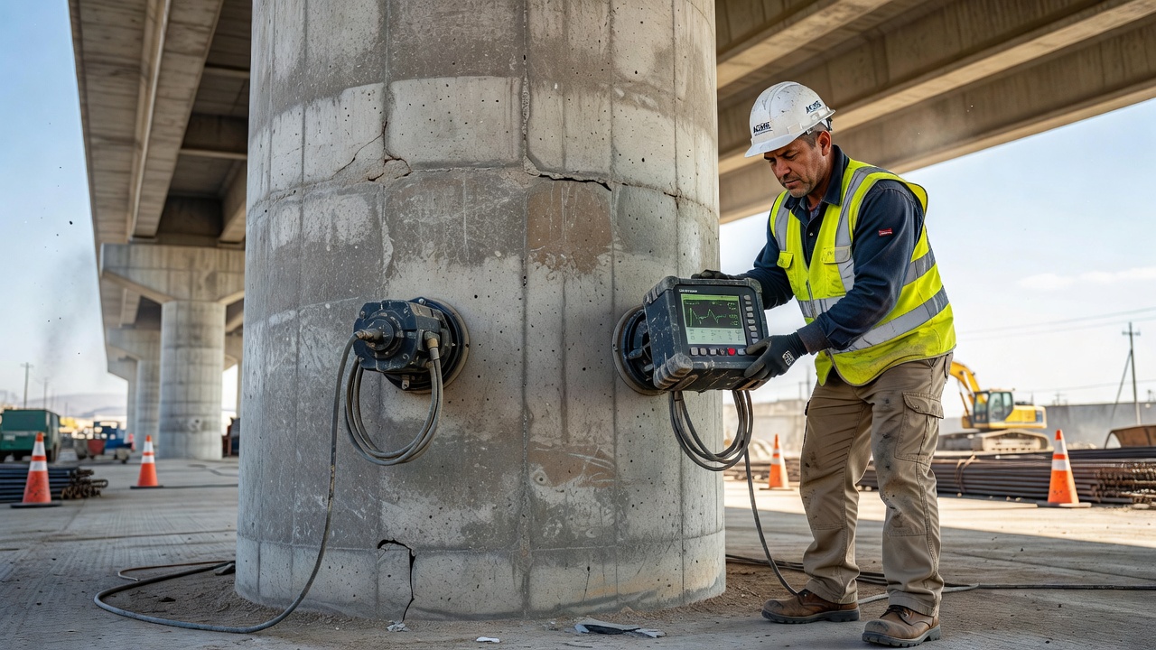
Measurement Principle. The UPV instrument consists of a portable electronic unit containing a pulse generator, a timing circuit with resolution of 0.1 microseconds, a receiver/amplifier, and a digital display. The system uses two piezoelectric transducers: a transmitting transducer that converts an electrical pulse into a mechanical vibration (the ultrasonic pulse), and a receiving transducer that converts the mechanical vibration received through the concrete back into an electrical signal. When the transmitted pulse arrives at the receiving transducer, the timing circuit is stopped and the transit time is displayed. The instrument must be capable of measuring transit times with an accuracy of ±0.1 µs over the measurement range. For concrete testing, the ultrasonic pulse typically has a center frequency between 20 kHz and 150 kHz, with 54 kHz and 82 kHz being common standard frequencies.
Transducer Configurations. UPV testing can be performed in three distinct transducer configurations depending on the accessibility of the test object:
Direct Transmission (Through-Transmission). The transmitting and receiving transducers are placed on opposite, parallel faces of the test object. This is the most sensitive configuration because the ultrasonic pulse travels through the full thickness of the material, and the receiving transducer captures the maximum signal energy. Direct transmission is preferred whenever access to both sides of the member is available. The received signal amplitude is maximized, and the measured velocity represents the average condition along the direct path. This configuration is ideal for measuring the thickness of concrete walls, slabs, and columns.
Semi-Direct Transmission. The transducers are placed on adjacent faces of the test object at a 90-degree angle. This configuration is used when access to two parallel faces is unavailable, such as at the corner of a concrete beam or at the edge a slab. The path length must be calculated using the Pythagorean theorem based on the transducer positions. The sensitivity is reduced compared to direct transmission because the received signal may be a combination of direct and reflected waves.
Indirect Transmission (Surface Transmission). Both transducers are placed on the same surface of the test object. The transmitting transducer is fixed at one location, and the receiving transducer is moved incrementally along the surface to measure travel times over increasing distances. This configuration is used when only one surface is accessible, such as on bridge decks, pavements, or tunnel linings. Indirect transmission is the least sensitive configuration because the pulse travels through near-surface material and may not penetrate deeply into the member. The velocity measured by the indirect method is typically slightly lower than the direct velocity due to the presence of surface effects and the complex wave path that involves both compression and surface wave components.
UPV Data Interpretation. The measured pulse velocity is interpreted in terms of concrete quality using established classification criteria. According to widely accepted guidelines published in ACI literature and international research:
| UPV Range (m/s) | UPV Range (ft/s) | Concrete Quality Classification |
|---|---|---|
| > 4,500 | > 14,800 | Excellent — very high density, homogeneous |
| 3,500 – 4,500 | 11,500 – 14,800 | Good to Very Good — sound concrete |
| 3,000 – 3,500 | 9,800 – 11,500 | Fair — possible porosity or minor defects |
| 2,000 – 3,000 | 6,600 – 9,800 | Poor — significant internal defects present |
| < 2,000 | < 6,600 | Very Poor — major voids or damage |
These classifications are indicative and must be calibrated for specific concrete mixtures, aggregate types, moisture conditions, and age. The presence of reinforcing steel in the direct path can produce artificially high velocity readings because wave travel through steel (approximately 5,900 m/s) is faster than through concrete. When testing near embedded reinforcement, the transducer positions should be oriented to avoid direct wave travel along the reinforcing bars.
UPV Applications in Quality Control. UPV testing serves as a primary tool for assessing concrete uniformity in new construction. During concrete placement, UPV can identify areas of inconsistent compaction, segregation, or inadequate curing. The method is specified in quality assurance programs for major infrastructure projects including bridge decks, retaining walls, and airport pavements. By establishing a baseline UPV map of a structure, subsequent monitoring can detect changes in concrete condition over time due to environmental exposure, chemical attack, or mechanical loading.
Pulse-Echo Technique. The pulse-echo method uses a single transducer that functions as both transmitter and receiver. The transducer generates a short burst of ultrasonic energy and then switches to receive mode to listen for echoes reflected from internal discontinuities or from the far boundary of the test object. The time delay between the transmitted pulse and the received echo is directly proportional to the distance to the reflecting feature: d = V × t / 2, where d is the distance to the reflector, V is the wave velocity in the material, and t is the round-trip transit time. The pulse-echo method requires access to only one surface of the test object, making it particularly useful for inspecting in-service structures where only one side is exposed.
A-Scan Display. The most basic pulse-echo display is the A-scan (amplitude scan), where the horizontal axis represents time (or distance) and the vertical axis represents signal amplitude. An A-scan shows the initial pulse (front surface reflection), followed by any intermediate echoes from internal defects, and finally the back-wall echo from the opposite surface. The position and amplitude of intermediate echoes indicate the depth and relative size of internal reflectors. An experienced UT technician interprets A-scan patterns to distinguish between genuine defects and geometric reflections from changes in section, attached components, or material features.
B-Scan and C-Scan Imaging. More advanced displays include B-scan, which produces a cross-sectional image of the test object by plotting the transducer position along one axis and the echo arrival time (depth) along the other axis, with signal amplitude represented by brightness or color. C-scan produces a plan-view image by plotting transducer position in two axes while gating on a specific depth range, creating a map of reflectors at a particular depth. These imaging modes are widely used in automated scanning systems for corrosion mapping, composite delamination detection, and uniform thickness evaluation.
Phased Array Ultrasonic Testing (PAUT). Phased array ultrasonic testing is an advanced UT technique that uses a transducer containing multiple small piezoelectric elements arranged in a linear or matrix array. Individual elements, typically 16 to 256 in a single probe, are pulsed independently with precise timing delays (measured in nanoseconds). By controlling the timing of each element’s excitation, the ultrasonic beam can be electronically steered through a range of angles and dynamically focused at multiple depths without physically moving the probe.
Beam Steering and Focusing. In PAUT, the focal law or delay law defines the firing sequence for each element. By applying progressively delayed pulses to adjacent elements, the wavefronts from individual elements combine constructively according to Huygens’ principle to form a wavefront propagating at a specific angle. The steering angle (θ) is determined by the time delay between elements (Δt) and the element pitch (p): sin θ = V × Δt / p. By adjusting the delays, a single PAUT probe can generate multiple angles from, for example, 35° to 70°, allowing comprehensive inspection of welded joints with complex geometries. Electronic focusing is achieved by applying a concave delay profile that causes the wavefront to converge at a selected depth, concentrating acoustic energy into a narrow focal zone for improved resolution and sensitivity.
PAUT Advantages. Compared to conventional single-element UT, PAUT offers several significant advantages. Speed is the most notable — a single PAUT probe with electronic scanning can inspect a weld in a fraction of the time required for conventional UT with multiple single-element probes at discrete angles. Imaging capability provides intuitive visual displays including sectorial scans (S-scans) that show the inspected cross-section in real time, linear scans showing the full weld volume, and top views for defect mapping. Improved probability of detection (POD) is achieved through multiple-angle coverage that ensures optimal orientation for detecting planar defects regardless of their alignment. Data archiving provides permanent records of complete inspections for regulatory compliance and trend analysis. Smaller access requirement is another benefit — a single PAUT probe can replace multiple conventional probes, requiring less surface area for inspection.
PAUT Applications in Infrastructure. The Federal Highway Administration (FHWA) identifies PAUT as a key nondestructive evaluation technology for bridge inspection. For steel bridge members, PAUT is used to detect cracks, weld flaws (lack of fusion, slag inclusions, porosity, undercut), and fatigue cracks in critical details. For concrete structures, low-frequency PAUT (25–100 kHz) with specialized dry-point contact transducers can image voids, tendon ducts, honeycombing, and delamination in bridge decks, columns, and retaining walls. In airport pavement applications, PAUT is used to evaluate the condition of runway pavements and detect debonding between overlay layers.
Ultrasonic Testing Instruments. Modern UT instruments range from simple thickness gauges to advanced phased array systems with full imaging capabilities. The essential components of any UT system include: a pulser/receiver that generates high-voltage electrical pulses (typically 100–400 V) to excite the transducer and amplifies the returning signals (gain range typically 0–110 dB); a timing circuit with microsecond or nanosecond resolution for measuring transit times; a signal processing unit for filtering, averaging, and digitizing waveforms; and a display for presenting A-scan, B-scan, or C-scan data. Portable instruments weigh as little as 2 kg and are designed for field use with battery operation extending 8–12 hours. Many modern instruments include WiFi connectivity, GPS tagging of inspection locations, and cloud-based data management.
Transducer Types. The transducer is the critical component that converts electrical energy into mechanical ultrasonic vibrations and vice versa via the piezoelectric effect. When a voltage is applied to a piezoelectric crystal (typically lead zirconate titanate — PZT), the crystal deforms mechanically, producing a sound wave. Conversely, when a sound wave strikes the crystal, it produces a voltage that is detected by the instrument.
| Transducer Type | Frequency Range | Typical Applications |
|---|---|---|
| Contact transducers | 0.5 – 20 MHz | General flaw detection, thickness gauging in steel |
| Angle beam transducers | 1 – 10 MHz | Weld inspection using shear waves at 45°, 60°, 70° |
| Delay line transducers | 5 – 100 MHz | Near-surface resolution, thin materials |
| Immersion transducers | 1 – 200 MHz | Automated scanning with water coupling |
| Dry point contact (DPC) | 20 – 150 kHz | Concrete testing without couplant |
| Phased array probes | 1 – 15 MHz | PAUT weld inspection, electronic beam steering |
| Low-frequency concrete probes | 24 – 150 kHz | UPV testing of concrete |
For concrete testing, the transducers must operate at frequencies low enough to penetrate the heterogeneous aggregate matrix. Standard UPV concrete transducers operate at 54 kHz or 82 kHz, with probe diameters of 40–50 mm (1.5–2 inches). The piezoelectric elements in concrete transducers are typically larger than those used in steel testing to generate sufficient acoustic power at lower frequencies.
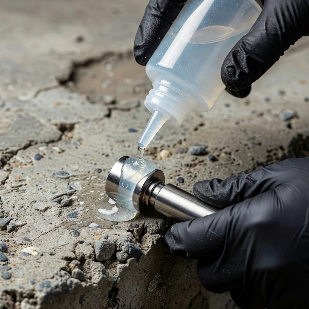
Couplant Function and Selection. The couplant is a material interposed between the transducer face and the test surface to permit efficient transmission of ultrasonic energy. The necessity of couplant arises from the extreme acoustic impedance mismatch between solids and air. At a typical transducer-to-air interface, approximately 99% of the ultrasonic energy is reflected, making effective acoustic coupling impossible without a couplant. The couplant displaces air from the interface and provides a continuous acoustic path with impedance intermediate between the transducer and the test material.
The selection of the appropriate couplant depends on five primary factors. Surface texture determines couplant viscosity requirements — rough, porous surfaces like concrete require thick, high-viscosity couplants (petroleum jelly, heavy grease, or proprietary concrete couplants) to fill surface irregularities, while smooth machined surfaces can use thin, low-viscosity couplants (glycerin, light oils, water-based gels) that allow the transducer to glide easily. Inspection angle dictates whether a couplant can remain in place — vertical and overhead inspections require thixotropic or high-viscosity couplants that cling to the surface without dripping. Temperature is critical for high-temperature applications (such as hot pipes or operating equipment) where standard couplants would decompose, burn, or auto-ignite — specialized high-temperature couplants are formulated to maintain acoustic coupling at temperatures up to 500°C with known auto-ignition temperatures. Material compatibility is essential for sensitive applications — aerospace-approved couplants must be independently tested to guarantee no corrosion, stress cracking, or hydrogen embrittlement, while nuclear industry couplants must meet low halogen and sulfur content requirements. Couplant removal is an operational consideration — water-soluble couplants are easily cleaned with water, while grease-based couplants require solvent cleaning and may leave residues.
For concrete UPV testing, common couplants include petroleum jelly, glycerin, aqueous gels, and kaolin-glycerol pastes. The couplant layer must be as thin as practical — a thick couplant layer can cause phase cancellation and signal distortion, particularly at higher frequencies where the couplant thickness may approach a significant fraction of the ultrasonic wavelength.
Data Acquisition and Processing. Modern UT data acquisition systems digitize analog waveforms at sampling rates of up to 100 MHz or higher, providing 8 to 16 bits of amplitude resolution. Acquired data is processed using digital filters, rectification (half-wave or full-wave), and smoothing algorithms. Advanced systems incorporate full matrix capture (FMC) and total focusing method (TFM) algorithms that capture time-domain signals from every element pair in a phased array probe, then computationally focus at every point in the inspection volume for the highest possible image resolution. These techniques are at the forefront of UT technology and are increasingly specified for critical infrastructure inspections.
UPV testing is one of the most effective volumetric NDT methods for detecting and characterizing internal defects in concrete structures. The technique is sensitive to any condition that alters the density, elastic modulus, or continuity of the concrete medium, which affects the propagation velocity and amplitude of ultrasonic waves.
Crack Detection and Depth Measurement. Surface-breaking cracks disrupt the continuity of the concrete, forcing ultrasonic waves to travel around the crack tip or through a longer path. The presence of a crack reduces the apparent pulse velocity compared to sound concrete and reduces the received signal amplitude. The depth of a surface-breaking crack can be estimated using the indirect transmission method described in ASTM C597. Transducers are positioned on the same surface on either side of the crack at increasing distances. By plotting the transit time versus transducer separation distance, two regression lines are obtained — one for measurements with both transducers on the same side of the crack and one for measurements across the crack. The intersection point of these two lines provides an estimate of the crack depth. This method can typically measure crack depths up to 200–300 mm (8–12 inches) with an accuracy of approximately ±15%, depending on crack width and concrete properties. The technique works best for cracks filled with air or water, while cracks filled with fine debris or partially closed cracks may produce unreliable results.
Void Detection. Voids and air pockets within concrete create zones where ultrasonic waves are severely attenuated or completely blocked due to the extreme acoustic impedance mismatch between concrete and air. When a void lies within the direct transmission path between transducers, the received signal amplitude drops significantly and the measured transit time increases (apparent velocity decreases) as the wave diffracts around the void. Large voids may completely block the direct transmission, requiring indirect detection through diffracted signals. UPV void detection is typically performed on a grid pattern across the test surface, with measurements at spacings of 150–300 mm (6–12 inches) depending on the minimum void size of interest. The resulting velocity map identifies low-velocity zones that correspond to void locations. The technique can detect voids as small as 20–30 mm (0.8–1.2 inches) in diameter under favorable conditions.
Delamination Detection. Delaminations are planar separations parallel to the concrete surface, typically caused by corrosion of embedded reinforcing steel, freeze-thaw damage, or overstress. Delaminations create a thin air gap that reflects ultrasonic energy, preventing transmission to deeper layers. In direct transmission, a delamination causes a complete loss of received signal when the transmission path crosses the delamination plane. In the indirect method, delaminations cause a sharp increase in apparent pulse velocity as the wave travels through the sound concrete layer above the delamination. Tomographic imaging techniques using multiple transducer positions can map the lateral extent and depth of delaminations with good accuracy.
Honeycombing Detection. Honeycombing refers to areas of concrete where the mortar failed to fill the spaces between coarse aggregate particles, leaving interconnected voids. The honeycombed zone has lower density, reduced elastic modulus, and numerous internal air-solid interfaces that scatter and attenuate ultrasonic waves. UPV measurements through honeycombed concrete show significantly reduced velocities (often 1,500–2,500 m/s or 4,900–8,200 ft/s) depending on the severity of the honeycombing, accompanied by strong signal attenuation. The velocity reduction correlates with the volume fraction of voids in the honeycombed zone. Tomographic reconstruction using multiple intersecting UPV paths can delineate the boundaries of honeycombed regions and estimate their severity.
Grid Mapping and Contour Plots. The standard procedure for detecting concrete defects with UPV involves establishing a measurement grid on the test surface with grid spacing of 150–600 mm (6–24 inches). UPV measurements are taken at each grid intersection point, and the resulting velocity data is plotted as a contour map or velocity isopleth that visualizes spatial variations in concrete quality. Low-velocity anomalies appearing on the contour map indicate areas requiring further investigation. For bridge decks, a typical survey uses a 300 mm (12 inch) grid spacing to achieve sufficient resolution for detecting delaminations and voids. The contour map approach allows rapid identification of problem areas and provides a permanent record of the structure’s condition.
UPV testing does not measure concrete compressive strength directly. However, extensive research over several decades has established that ultrasonic pulse velocity correlates with concrete compressive strength through empirical relationships. The correlation exists because both UPV and compressive strength depend on the same fundamental material properties — the elastic moduli, density, and internal structure of the concrete. The relationship between UPV (V) and compressive strength (f’c) is typically modeled using exponential, power, or logarithmic regression equations.
Empirical Correlation Models. The most commonly used correlation models include:
The specific coefficients vary with aggregate type, maximum aggregate size, cement type, water-to-cement ratio, admixtures, age, curing conditions, and moisture content. Therefore, a site-specific correlation curve must be established for each project by testing companion specimens (cylinders or cores) for both UPV and compressive strength. The International Atomic Energy Agency (IAEA) and ACI 228.2R both recommend that at least 15 to 20 paired data points be obtained for establishing a reliable correlation.
Factors Affecting UPV-Strength Correlation. Several factors influence the relationship between UPV and compressive strength and must be considered when interpreting results. Aggregate type is the most significant factor — concrete made with lightweight aggregates has lower UPV at the same strength compared to normal-weight aggregate concrete. Aggregate size affects the correlation because larger aggregates provide wave paths with fewer interfaces, potentially increasing velocity independent of strength. Moisture content has a strong effect — saturated concrete can exhibit 2–5% higher UPV than dry concrete of the same strength, which may result in overestimation of strength if the correlation was established with dry specimens. Concrete age affects both UPV and strength differently — early-age concrete may show rapid strength gain with relatively modest velocity increases, while mature concrete may show strength increases without corresponding velocity changes. Curing conditions influence the degree of hydration and the resulting microstructure, affecting both properties.
Dynamic Modulus of Elasticity. UPV measurements can be used to calculate the dynamic Young’s modulus of elasticity (Ed) of concrete using the formula: Ed = ρ × V² × (1+ν)(1-2ν) / (1-ν), where ρ is density, V is P-wave velocity, and ν is Poisson’s ratio. For normal-weight concrete (ρ ≈ 2,400 kg/m³ and ν ≈ 0.2), this simplifies to approximately Ed ≈ 2.4 × V² × 10⁻⁶ (GPa when V is in m/s). The dynamic modulus is typically 15–40% higher than the static modulus obtained from compression testing, but the dynamic value is useful for comparing relative stiffness between different areas of a structure and for detecting deterioration that reduces elastic stiffness.
Practical Limitations of UPV-Strength Correlation. The accuracy of strength prediction from UPV is typically ±15–25% when a site-specific correlation is established. Without site-specific calibration, the accuracy may be ±30% or worse. ACI 228.2R emphasizes that UPV should not be relied upon as the sole method for strength evaluation of concrete structures. UPV is most valuable for assessing uniformity and relative quality — identifying areas where the concrete differs from the norm — rather than for predicting absolute strength values. For definitive strength determination, concrete core testing remains the reference standard, with UPV providing guidance on core locations and interpolation between core test results.
Ultrasonic testing is one of the primary NDT methods for inspecting steel bridge members, particularly welded connections where internal discontinuities cannot be detected by surface inspection methods. The FHWA identifies UT as a critical technology for bridge safety inspection because it can detect both embedded and surface-breaking cracks in steel components, measure remaining thickness in corroded areas, and evaluate the integrity of welded details that are subject to fatigue loading.
Weld Inspection with UT. Steel bridge welds are inspected using angle beam shear wave techniques where the ultrasonic beam is directed into the weld at a specific angle (typically 45°, 60°, or 70°) to detect planar defects oriented perpendicular or oblique to the inspection surface. The inspection is performed according to ASTM E164 — Standard Practice for Contact Ultrasonic Testing of Weldments and the American Welding Society AWS D1.5 — Bridge Welding Code. The procedure involves scanning the weld and heat-affected zone with the transducer positioned on the base metal adjacent to the weld, using a calibrated reference block to set the sensitivity level. Common weld discontinuities detected by UT include:
Ultrasonic Thickness Measurement. UT is routinely used to measure the remaining thickness of steel bridge members affected by corrosion, erosion, or wear. The thickness is measured using the pulse-echo method with a single transducer placed on the accessible surface. The time between the initial pulse and the back-wall echo is converted to thickness using the known velocity of sound in steel (approximately 5,900 m/s for longitudinal waves). Modern ultrasonic thickness gauges can measure steel thickness from 0.5 mm to 500 mm with an accuracy of ±0.1 mm or better. For bridge inspection, thickness measurements are taken at multiple points on girder flanges, webs, stiffeners, and connection plates in areas identified as susceptible to corrosion — typically at bearing locations, expansion joints, deck drainage outlets, and areas of standing water or deicing chemical exposure.
Corrosion Mapping. Advanced UT systems with automated scanning capability can produce corrosion maps (C-scans) showing thickness variations across large areas of steel plate. The scanning system uses an encoded encoder to track transducer position while acquiring thickness data at regular intervals (typically 1–5 mm spacing). The resulting color-coded thickness map reveals areas of localized corrosion pitting, general section loss, and the remaining sound metal thickness. This technique is particularly valuable for inspecting steel bridge girders at bearing locations and in splash zones where corrosion rates are highest.
Fatigue Crack Detection and Sizing. Fatigue cracks in steel bridges typically initiate at weld toes, weld terminations, cope holes, and other stress concentration points. UT can detect fatigue cracks before they become visually apparent, with detection limits as small as 1–2 mm (0.04–0.08 inches) for surface-breaking cracks and 2–5 mm (0.08–0.2 inches) for embedded cracks under favorable conditions. The crack tip diffraction technique, also known as Time-of-Flight Diffraction (TOFD), uses the diffracted signals from the crack tips to measure crack height with high accuracy (±0.5 mm). TOFD is increasingly used for critical fatigue-prone details in steel bridges to monitor crack growth rates and inform fracture-critical inspection programs.
PAUT for Steel Bridges. The FHWA promotes PAUT as a preferred technology for steel bridge weld inspection because it provides comprehensive volumetric coverage of the weld in a single scan. A typical PAUT setup for bridge weld inspection uses a linear array probe with 64–128 elements operating at 5–10 MHz, mounted on a wedge that generates shear waves at angles from 35° to 70°. The instrument displays a sectorial scan (S-scan) showing the weld cross-section in real time, allowing the operator to evaluate the size, shape, and orientation of any detected indications. PAUT has been shown to improve the probability of detection for weld flaws compared to conventional UT, particularly for planar defects that are oriented at unfavorable angles for single-angle inspection.
Ultrasonic testing is governed by comprehensive international, national, and industry-specific standards that define equipment requirements, test procedures, calibration methods, data interpretation, and personnel qualifications.
Concrete Testing Standards.
ASTM C597 — Standard Test Method for Pulse Velocity Through Concrete is the primary standard for UPV testing worldwide. Originally published in 1970 and regularly updated, the standard specifies the test apparatus requirements including pulse generator, timing circuit (resolution of 0.1 µs), transducers (20–100 kHz for concrete), and display. The standard defines the three transducer configurations (direct, semi-direct, indirect) and provides measurement procedures. It specifies that at least five measurements should be taken at each test location, with the median value reported. The standard also requires temperature correction of velocity readings when concrete temperature deviates from the calibration standard.
ACI 228.2R — Nondestructive Test Methods for Evaluation of Concrete Structures is a comprehensive report that provides guidance on selecting and applying NDT methods, including detailed sections on UPV equipment, test procedures, data interpretation, and correlation with concrete strength and quality. The report emphasizes the importance of understanding factors that affect UPV readings and the limitations of the method. It provides recommended velocity ranges for concrete quality classification and procedures for detecting voids, cracks, and delamination.
ASTM C1383 — Standard Test Method for Measuring the P-Wave Speed and the Thickness of Concrete Plates Using the Impact-Echo Method is related to the pulse-echo technique and provides a method for determining P-wave velocity in concrete using the impact-echo method, which can be correlated with UPV results.
Steel Testing Standards.
ASTM E164 — Standard Practice for Contact Ultrasonic Testing of Weldments governs UT procedures for detecting discontinuities in welded joints. The standard specifies equipment requirements, calibration procedures using reference blocks, scanning patterns, evaluation of indications, and reporting requirements. It covers all weld types including butt, fillet, and T-joint welds.
AWS D1.5 — Bridge Welding Code is the primary specification for bridge weld fabrication and inspection in the United States. It establishes acceptance criteria for UT-discontinuities based on indication amplitude, length, and location. The code specifies that all complete joint penetration (CJP) groove welds in bridge main members must be inspected by UT.
ASTM E317 — Standard Practice for Evaluating Performance Characteristics of Ultrasonic Pulse-Echo Testing Systems Without the Use of Electronic Measurement Instruments provides procedures for verifying UT system performance including sensitivity, resolution, and dead zone.
ISO Standards. The International Organization for Standardization has published several UT standards: ISO 16810 (General principles of UT), ISO 16811 (Sensitivity and range setting), ISO 16823 (Through-transmission technique), ISO 16826 (Techniques for detection of discontinuities perpendicular to the surface), and ISO 18563 (Phased array UT — equipment and systems). These standards are harmonized with EN standards in Europe and increasingly adopted worldwide.
Personnel Qualification Standards. UT personnel must be certified according to recognized qualification standards: ISO 9712 (Non-destructive testing — Qualification and certification of NDT personnel), ASNT SNT-TC-1A (Recommended Practice for Personnel Qualification and Certification in Nondestructive Testing), and NAS 410 (NAS Certification & Qualification of Nondestructive Test Personnel — aerospace focus). Certification levels range from Level I (trainee performing specific tests under supervision) to Level III (qualified to develop procedures, approve techniques, and certify personnel). For infrastructure applications, Level II certification in UT is typically required for independent inspection and data interpretation.
Inherent Limitations of UT. Despite its power and versatility, ultrasonic testing has several inherent limitations that must be understood by inspectors and engineers when planning inspection programs and interpreting results.
Material Limitations. UT requires good acoustic coupling between the transducer and the test surface. Rough, curved, or uneven surfaces make coupling difficult and may require extensive surface preparation (grinding, sanding) that adds time and cost. Materials with coarse grain structure (e.g., cast stainless steel, large-grained aluminum) scatter ultrasonic energy strongly, limiting the effective penetration depth. Concrete’s inherent heterogeneity limits the maximum practical testing frequency to 150 kHz, which constrains spatial resolution to centimeter-scale defects, whereas steel testing at MHz frequencies can resolve millimeter or sub-millimeter defects.
Geometric Limitations. Complex geometries with varying cross-sections, curved surfaces, or limited access areas may be difficult or impossible to inspect with standard UT techniques. Thin sections (less than 5 mm for steel, less than 50 mm for concrete) present challenges because the front surface echo and back-wall echo may overlap, masking internal indications. Orientation of planar defects relative to the ultrasonic beam is critical — a crack oriented parallel to the sound beam may produce little or no echo. Multiple-angle inspection (as provided by PAUT) mitigates this limitation but may not completely eliminate it.
Interpretation Limitations. UT signals require skilled interpretation to distinguish genuine defect indications from geometric reflections, material noise, and non-relevant indications (such as changes in section thickness, attached components, or material properties). The interpretation of UT signals in concrete is particularly challenging because the heterogeneous aggregate matrix produces complex signal patterns that can mask defect echoes. False positives (reporting defects where none exist) and false negatives (missing actual defects) are risks that are managed through technician training, calibration procedures, and complementary NDT methods.
Couplant Dependency. Standard UT methods require couplant for energy transmission into the test material. This necessitates surface contact and may require cleaning of the test surface before and after inspection. In applications where contamination from couplant residues is unacceptable, alternative methods or specialized couplants (such as dry point contact transducers for concrete) may be required.
Surface Temperature Limitations. UT transducers and couplants have specified temperature operating ranges. At elevated temperatures, couplants may decompose or lose acoustic properties, and transducer piezoelectric elements may depolarize. Specialized high-temperature transducers and couplants are available but add complexity and cost.
Complementarity with Visual Inspection. UT and visual inspection (VT) are complementary NDT methods that provide different and overlapping information about structural condition. Visual inspection is always the first step in any inspection program because it identifies surface-visible defects, determines access conditions, and guides the selection and application of subsequent NDT methods. The ASNT and ACI frameworks both specify that NDT methods including UT should be applied in conjunction with visual inspection, not as a replacement for it.
Visual Inspection Capabilities. VT can detect surface defects including cracks, spalls, scaling, discoloration, corrosion staining, surface deterioration, joint sealant failure, drainage problems, and attachment condition. VT provides broad area coverage quickly and inexpensively, establishing a baseline condition assessment and identifying specific areas requiring detailed investigation.
UT Capabilities Beyond VT. UT detects subsurface defects that are invisible to VT, including internal voids, honeycombing, delamination, internal cracking, weld discontinuities, and internal corrosion damage. UT measures material thickness, providing quantitative data on section loss that cannot be obtained from surface inspection. UT assesses material properties including elastic moduli and uniformity, which VT cannot evaluate. UT can detect defects below coatings, paints, or surface treatments that obscure visual inspection.
Multi-Tier Inspection Approach. A recommended approach for infrastructure inspection follows a multi-tiered methodology. Tier 1 — Visual inspection provides broad coverage, identifies obvious defects, and selects areas for further investigation. Tier 2 — Surface NDT methods (rebound hammer, Schmidt hammer, dye penetrant, magnetic particle testing) provide additional surface and near-surface information. Tier 3 — Volumetric NDT methods (UT, impact-echo, ground-penetrating radar, radiography) provide detailed subsurface information for identified areas of concern. Tier 4 — Partially destructive testing (core sampling, pullout tests, breakout) provides definitive material property data for critical areas identified by NDT methods.
Cost-Effectiveness of Combined Approach. The combination of visual inspection followed by targeted UT reduces inspection costs while improving defect detection reliability. VT screens large areas rapidly at low cost, identifying approximately 80% of observable defects. Targeted UT then investigates specific areas of concern identified by VT, providing volumetric data on approximately 20% of the structure. This combined approach optimizes the detection capabilities of both methods while controlling inspection costs. For critical infrastructure such as bridges, airport pavements, and nuclear facilities, the combination of VT and UT is specified by regulatory codes and standards as the minimum inspection requirement for ensuring structural safety and serviceability.
Data Integration and Digital Twin Applications. Modern inspection programs integrate visual inspection data (photographs, video, annotated drawings) with UT data (velocity maps, thickness plots, A-scan records) in a common digital platform that creates a condition data model (digital twin) of the inspected structure. This digital representation allows comparison of inspection results over time (change detection), correlation between surface and subsurface conditions, and automated identification of critical areas requiring intervention. TarmacView’s drone-based visual inspection platform provides high-resolution surface imagery that can be spatially registered with UT survey grids, enabling direct correlation between observed surface distress patterns and subsurface condition data.
Conclusion. Ultrasonic testing is a mature, well-established, and continuously evolving NDT method that provides essential volumetric information about the internal condition of concrete and steel structures. From basic UPV quality assessment to advanced PAUT imaging of welds, UT delivers quantitative data that cannot be obtained from surface inspection alone. The method’s limitations — sensitivity to surface condition, material heterogeneity, and interpretation complexity — are well understood and managed through standards, technician certification, and complementary NDT methods. For aviation infrastructure, UT plays a critical role in evaluating runway pavements, bridge decks, and structural members, complementing visual inspection methods to ensure the safety, reliability, and service life of airport facilities.
TarmacView provides expert non-destructive evaluation services for airfield pavements, bridge decks, and concrete infrastructure. Contact our team to schedule an ultrasonic testing inspection or assessment.
Impact-Echo is a stress-wave nondestructive testing method where a short-duration mechanical impact on a concrete surface generates stress waves that reflect fr...
Non-Destructive Testing (NDT) encompasses methods to evaluate material properties, detect defects, and assess structural condition without causing damage. For i...
Acoustic Emission (AE) is a passive non-destructive testing method that detects and locates transient stress waves generated by active defect processes — crack ...