Pavement Edge Drains
Edge drains are longitudinal subsurface drains installed along pavement edges to intercept and remove water from the pavement structure, preventing water-relate...
23 min read
Airport infrastructure
Pavement engineering
+3
Subsurface drainage systems — edge drains, underdrains, permeable bases, and drainage blankets — remove water from pavement structural layers, preventing pumping, freeze-thaw damage, and subgrade weakening. Drainage condition is a key inspection item across airport and highway pavements.
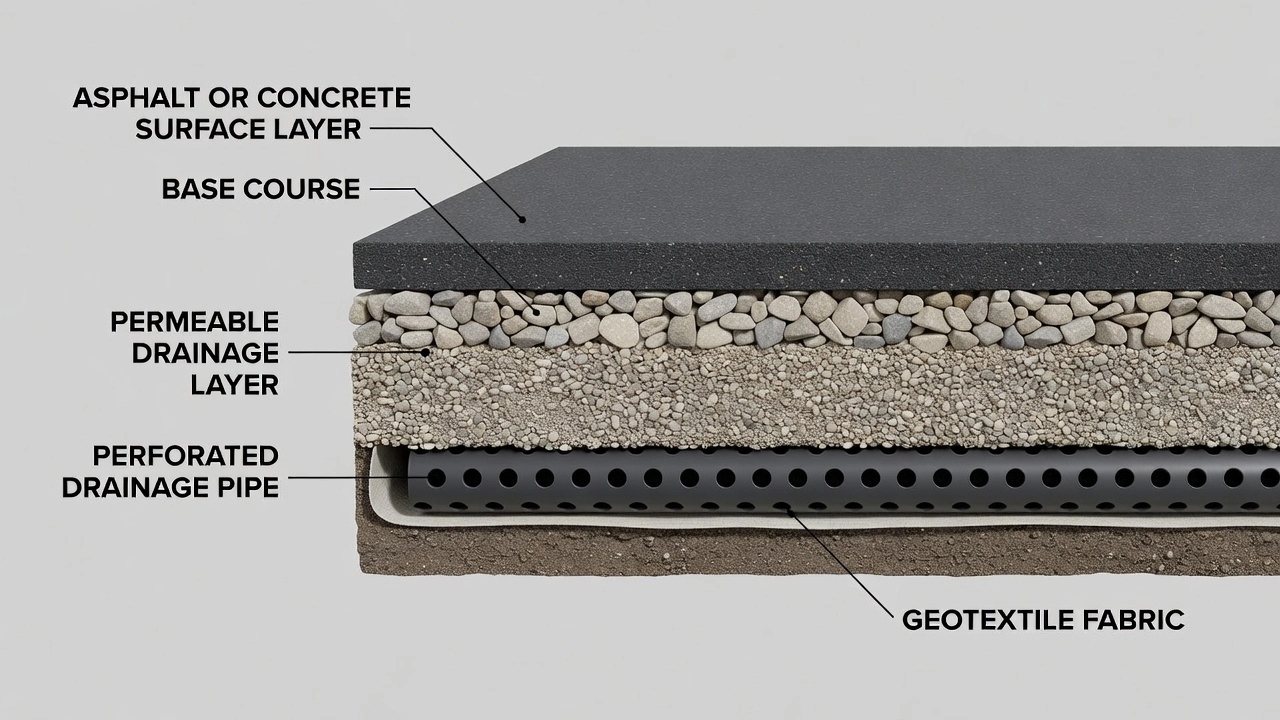
A subsurface drainage system for pavements is an engineered assembly of permeable layers, collector pipes, geotextile separators, and outlet structures designed to intercept, collect, and expel water that enters the pavement structure from above, below, or the sides. These systems are fundamental to pavement longevity — water is the single most destructive agent affecting pavement performance, and its removal is the most cost-effective strategy for extending service life.
The primary function of subsurface drainage is to remove free gravitational water from the pavement structural section within a specified time frame after a rainfall event. The AASHTO Guide for Design of Pavement Structures (1993) defines drainage quality based on time-to-drain: excellent drainage removes 50% of free water within 2 hours, good within 1 day, fair within 1 week, and poor within 1 month. Pavements that drain within hours rather than days experience dramatically longer service lives because the duration of saturation — and therefore the opportunity for moisture-related damage — is minimized.
FHWA research summarized in Demonstration Project 87 (Drainable Pavement Systems) found that surface infiltration through joints, cracks, and pavement edges is the single largest source of moisture entering the pavement structure. Studies by the Minnesota Department of Transportation indicate that up to 40% of rainfall can enter a pavement through its surface. Once inside, this water becomes trapped within the pavement layers if no drainage path exists, leading to progressive structural deterioration.
The FAA Advisory Circular 150/5320-5D (Airport Drainage Design) provides comprehensive guidance for subsurface drainage at airports, emphasizing that groundwater control, usually through interception and removal before it enters the pavement section, is an essential part of pavement design. For pavements constructed below the permanent or seasonally high water table, drainage systems must perform reliably or very rapid pavement failure will occur. The FAA recommends redundancy in drainage design, including installation of both underdrains and edge drains, along with monitoring systems to ensure continual function.
The fundamental purpose of subsurface drainage is to prevent the accumulation of free water within the pavement structural section. Water enters pavements through multiple pathways: infiltration through surface cracks and joints, lateral flow from shoulders and adjacent terrain, upward capillary rise from a high water table, and vapor condensation on the underside of impermeable surfaces. Regardless of the source, water trapped within pavement layers initiates a cascade of deterioration mechanisms.
Moisture damage in flexible pavements manifests as stripping of asphalt binder from aggregate, modulus reduction of up to 30% or more in saturated asphalt concrete, loss of tensile strength, accelerated fatigue cracking, and rutting from weakened base and subgrade layers. The FHWA Geotechnical Aspects of Pavements Reference Manual (NHI-05-037) documents that saturation can reduce the dry modulus of asphalt by 30% or more, while added moisture in unbound aggregate base and subbase layers results in stiffness losses on the order of 50% or more. Saturated fine-grained roadbed soils can experience modulus reductions exceeding 50%.
Moisture damage in rigid pavements manifests as pumping (ejection of water and fine particles from beneath slabs), erosion of base and subgrade materials at joints and cracks, faulting (vertical displacement at joints caused by loss of foundation support), D-cracking from aggregate freeze-thaw expansion, and loss of load transfer efficiency at joints. The combined effect of these distress mechanisms is a pavement that fails structurally years or decades before its design life.
The three principal approaches to moisture control in pavements are: prevent moisture from entering the pavement system through surface seals and effective joint maintenance; use moisture-insensitive materials such as treated bases and stabilized subgrades; and quickly remove moisture that does enter through subsurface drainage. No single approach is sufficient alone. The most effective designs employ all three strategies in combination.
Subsurface drainage is most critical under the following conditions identified in NCHRP 1-37A: wet climates with annual precipitation exceeding 508 mm (20 inches), freeze climates with annual freezing index exceeding 83 °C-days (150 °F-days), subgrade permeability less than 3 m/day (10 ft/day), and heavy traffic volumes exceeding 2.5 million equivalent single axle loads over a 20-year design life. Under these conditions, subsurface drainage transitions from a desirable feature to a structural necessity.
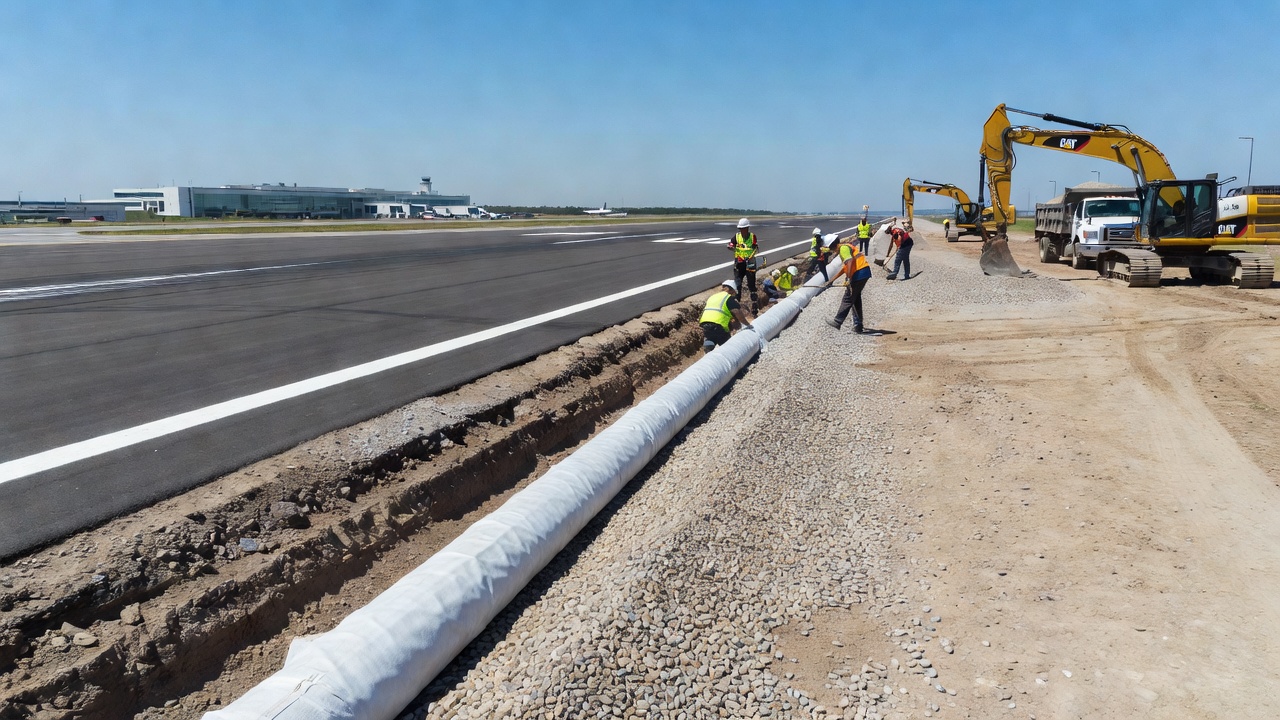
Pavement edge drains are longitudinal drainage systems installed parallel to the traffic lane along the edge of the pavement. They consist of a narrow trench excavated along the pavement edge, lined with geotextile fabric, containing a perforated collector pipe surrounded by clean aggregate backfill. The pipe is typically 100 mm to 150 mm (4 to 6 inches) in diameter and is sloped to convey water to regularly spaced outlet structures.
Edge drains collect water that infiltrates through the pavement surface and percolates downward through the base and subbase layers. The open-graded permeable base conveys water laterally to the edge drain, where it enters the perforated pipe through its openings and is conveyed to an outlet. The geotextile wrap prevents migration of fine soil particles from the adjacent subgrade into the aggregate backfill, which would clog the system over time.
The Missouri Department of Transportation (MoDOT) Engineering Policy Guide requires pavement edge drains for all new rigid or flexible pavements on medium and heavy-duty routes. Permeable base courses are provided on all heavy-duty pavements. Exceptions are permitted only where a minimum of 300 mm to 450 mm (12 to 18 inches) of daylighted rock base can be furnished on top of the subgrade, or where hydraulically placed sand fill comprises the top 1.2 m (4 ft) of embankment with sufficient soil cap on slopes.
Edge drains are typically spaced at intervals of 60 m to 150 m (200 to 500 feet) along the pavement, with outlet pipes extending to the ditch or drainage channel. The outlet pipe invert should be at least 150 mm (6 inches) and preferably 300 mm (12 inches) above the ditch flow line to prevent water from backing up into the pavement structure during high-flow events. Outlets are marked with “Drain” markers on steel posts for identification during maintenance inspections.
Underdrains are more general subsurface drainage installations that intercept groundwater moving through soil or rock strata. Unlike edge drains which primarily collect water from the pavement structure itself, underdrains are designed to lower the groundwater table, intercept seepage from adjacent slopes, or drain springs and wet seams encountered during construction.
Underdrains consist of a geotextile-lined trench, perforated plastic or corrugated metal pipe, and porous backfill. They may be oriented longitudinally (paralleling the roadway) as pavement cross drains or transverse (crossing beneath the pavement) as interceptor drains. The term “underdrain” is often used interchangeably with “subdrain” and encompasses a wider category than “edge drain.”
Pipe-aggregate underdrains use perforated pipe surrounded by clean aggregate, wrapped in geotextile. The pipe is laid with perforations facing downward to allow water entry from below while minimizing sediment entry from above. Perforated pipe is available in diameters from 150 mm to 450 mm (6 to 18 inches), selected based on the required drainage capacity. The aggregate backfill extends at least 300 mm (12 inches) above the top of pipe to provide adequate storage and conveyance capacity.
French underdrains, also called French drains, consist of fabric-wrapped coarse porous backfill in a trenched installation. No pipe is used except for a short length of metal pipe as an outlet. French drains function by storing water in the void spaces of the coarse aggregate and conveying it laterally to an outlet point. They are effective where the drainage demand is moderate and the available head (difference in elevation between inlet and outlet) is sufficient to drive flow through the porous media.
A permeable base is an open-graded aggregate layer placed directly beneath the pavement surface course, designed to rapidly convey infiltrated water laterally to edge drains or daylighted outlets. Permeable bases are distinguished from conventional dense-graded bases by their high void content and correspondingly high hydraulic conductivity.
Current FHWA guidance recommends permeable bases with permeability values of 150 to 240 m/day (500 to 800 ft/day). Earlier practice pursued much higher permeability values of 2,400 to 3,000 m/day (8,000 to 10,000 ft/day), but experience showed that these very open gradations lacked structural stability and were prone to segregation during construction. The current recommended range achieves an optimal balance between drainage capacity and structural stability.
Permeable bases may be untreated (consisting of open-graded aggregate alone), asphalt-treated (where 2% to 3% asphalt binder is added to provide cohesion while maintaining permeability), or cement-treated (where 4% to 6% cement is added to create a stabilized permeable layer). Asphalt-treated permeable bases offer good stability and flexibility, while cement-treated bases provide the highest strength and erosion resistance but require careful curing and are more susceptible to reflective cracking.
The thickness of a permeable base typically ranges from 100 mm to 150 mm (4 to 6 inches) for treated materials and up to 450 mm to 600 mm (18 to 24 inches) for untreated large-stone bases. The cross-slope of the permeable base should be at least 3% (approximately 0.36 inches per foot) to drive lateral drainage effectively. Inadequate cross-slope is the most common design deficiency in permeable base systems.
A drainage blanket is a thick, highly permeable layer placed across the full width of the pavement subgrade, typically 300 mm to 600 mm (12 to 24 inches) thick, constructed from large-size open-graded aggregate or crushed stone. Drainage blankets are used where the subgrade has low permeability and the water table is high, requiring continuous drainage across the entire pavement footprint rather than just at the edges.
Drainage blankets serve dual functions: they provide a capillary break that prevents upward moisture migration from the water table, and they convey infiltrated water laterally to edge drains or daylighted outlets. The large void spaces in the blanket material ensure that capillary forces, which are significant in fine-grained soils, are unable to draw water upward through the blanket.
The Missouri DOT has successfully used a thick (460 mm / 18 inch) unbound rock base as a drainage blanket on thousands of lane-miles of pavement since 1994. This material, specified as having no particle dimension exceeding 150 mm (6 inches) with at least 50% of particles exceeding half the lift thickness, provides both structural support and drainage. The top 50 mm (2 inches) consists of 50 mm maximum-size material or granular material with plasticity index not exceeding 10, providing a uniform surface suitable for paving.
Drainage blankets are particularly effective in cut sections where the pavement is below the surrounding groundwater level. In these conditions, the blanket acts as a permanent interceptor drain across the entire pavement width, preventing groundwater from reaching the base and subgrade layers. The daylighted edges of the blanket must be maintained clear of vegetation and debris to ensure continued outflow.
Interceptor drains, also called cross drains or transverse drains, are subsurface drains installed perpendicular to the pavement centerline that cut off lateral groundwater flow before it reaches the pavement structure. They are typically installed in cut sections where groundwater flows from adjacent higher ground toward the pavement.
Interceptor drains consist of a trench excavated across the groundwater flow path, backfilled with permeable aggregate, containing a perforated collector pipe. The drain is sloped to convey intercepted water to an outlet at the toe of the slope or into the roadway drainage system. The depth of the interceptor drain must extend below the anticipated seepage zone, typically 1 m to 3 m (3 to 10 feet) below the pavement subgrade level.
The design of interceptor drains requires careful hydrogeological investigation to determine the direction, depth, and quantity of groundwater flow. MoDOT Engineering Policy notes that groundwater movement in soil and rock strata can be very complex, influenced by seasons, surface topography, vegetation, and subsurface soil and rock profiles. Many interception requirements are identified during construction rather than during design, as groundwater sources may not be evident during dry-period soil surveys.
The drainage pipe is the primary conveyance element of the subsurface drainage system. Perforated pipe collects water along its length through slots or holes and conveys it to outlet structures. Pipe materials include PVC (polyvinyl chloride), HDPE (high-density polyethylene), and corrugated metal (galvanized steel or aluminum). For airport applications under airfield pavements, FAA Order 5300.1F specifies that plastic pipe shall comply with Item D-701, Pipe for Storm Drains and Culverts in AC 150/5370-10.
Pipe diameter is selected based on the required hydraulic capacity. Minimum diameter for edge drains is typically 100 mm (4 inches), with 150 mm (6 inches) being standard for most highway applications. Larger diameters of 200 mm to 450 mm (8 to 18 inches) are used where higher flows are anticipated, such as at the downstream ends of long drain runs or for interceptor drains handling significant groundwater flow.
Perforations are typically sized to allow water entry while excluding aggregate backfill material. Perforation patterns vary by pipe type: PVC and HDPE pipes have factory-cut slots or circular holes arranged in rows along the pipe length, while corrugated metal pipes have perforations in the valley of the corrugation. The open area of perforations should be sufficient to allow free water entry without creating excessive stress concentrations in the pipe wall.
Pipe joints must be designed to prevent infiltration of fine soil particles while accommodating thermal expansion and contraction. For PVC and HDPE pipes, solvent-weld or gasketed bell-and-spigot joints provide watertight connections. For corrugated metal pipes, band couplings with gaskets are used at joints. All pipes should be laid on a uniform bedding of crushed stone or sand to provide consistent support and maintain grade.
Geotextile is a permeable textile fabric used in drainage systems to separate aggregate backfill from surrounding soil while allowing water passage. The geotextile prevents migration of fine soil particles into the aggregate — a process called clogging — which would progressively fill the void spaces and reduce drainage capacity.
Two types of geotextile are used in drainage applications: woven and non-woven. Non-woven geotextiles are more commonly used in drainage due to their higher permeability and better filtration characteristics. The geotextile is specified by its apparent opening size (AOS), permittivity, and grab tensile strength. The AOS must be small enough to retain the soil particles but large enough to allow water passage without excessive head loss.
The geotextile wrap is installed by excavating the trench, lining the trench with geotextile fabric, placing the aggregate backfill and pipe, then folding the geotextile over the top of the aggregate before covering with select backfill. The overlap at the top should be at least 300 mm (12 inches) to provide continuous encapsulation. In some installations, geotextile is also placed between the permeable base and the subgrade as a separator layer, preventing migration of subgrade fines into the permeable base.
Proper geotextile selection and installation is critical to long-term drainage performance. Incorrect geotextile selection (AOS too large) allows soil migration and clogging of the aggregate. Excessively tight geotextile (AOS too small) restricts water flow and creates a hydraulic barrier. The geotextile must also be resistant to ultraviolet degradation, soil chemicals, and construction damage.
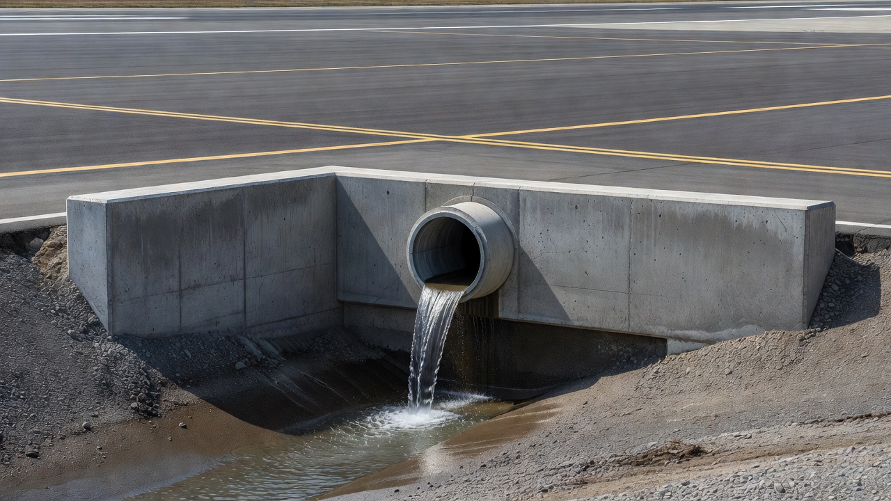
The outlet is the discharge point where drainage water exits the subsurface system. Outlet structures typically consist of a short length of non-perforated pipe extending from the collector pipe to the ditch, stream, or storm drain system. The outlet pipe connects to the collector pipe through a wye-fitting or tee-fitting and is laid at a positive slope to ensure gravity flow.
Outlet pipes must extend at least 150 mm (6 inches) and preferably 300 mm (12 inches) above the flow line of the receiving ditch or channel to prevent backwater effects during high-flow events. The outlet end may be fitted with a headwall — a concrete or metal structure that protects the pipe end, prevents erosion of the ditch slope, and provides a visible marker for maintenance personnel.
Erosion protection at the outlet is essential. The high-velocity discharge from drainage outlets can scour the ditch bottom and banks if not properly protected. Riprap aprons, concrete splash pads, or energy dissipators are installed at the outlet to absorb the energy of the discharging water and prevent erosion. The size of riprap required depends on the discharge velocity, with larger stone sizes needed for higher velocities.
Outlet spacing is determined by the length of the collector pipe run. Maximum recommended spacing between outlets is typically 150 m (500 feet) for highway pavements and 75 m to 100 m (250 to 330 feet) for airport pavements. Closer spacing reduces the head required to drive flow through the pipe and reduces the risk of blockage from sediment accumulation.
A cleanout is an access point in the drainage system that allows inspection, flushing, and rodding of the collector pipe. Cleanouts consist of a vertical pipe riser extending from the collector pipe to the surface, capped with a removable plug or cover. They are located at the upstream end of each drain run, at changes in direction, and at intervals not exceeding 75 m (250 feet) along straight runs.
Cleanouts serve three functions: they provide access for flushing the system with water to remove sediment accumulation, they allow CCTV camera insertion for internal pipe inspection, and they provide a point for rodding or jetting to clear obstructions. Cleanout risers are typically 150 mm (6 inches) in diameter and extend to a point flush with the pavement surface or shoulder, fitted with a heavy-duty cast iron or steel cap rated for traffic loading.
Proper cleanout design and installation is often overlooked but is essential for long-term maintenance. Cleanouts that are not clearly identified, buried under soil or vegetation, or installed with undersized access points become effectively unusable, making the drainage system unmaintainable. Each cleanout should be marked with a visible locator marker or flag to facilitate annual inspection and maintenance.
Drainage system inspection is a critical and often neglected component of pavement management. A subsurface drainage system that appears functional at the surface may be completely blocked or failed internally. Regular inspection — at least annually and preferably after major storm events — is essential to maintain drainage performance.
The outlet is the most visible and accessible component of the subsurface drainage system and the logical starting point for inspection. The inspector checks: is water flowing from the outlet during or after a rain event? A dry outlet during wet conditions may indicate a blockage upstream. Is the flow rate consistent with the catchment area and rainfall intensity? Reduced flow suggests partial blockage or clogging of the permeable base.
The outlet pipe end is inspected for physical damage: cracking, crushing, or displacement of the pipe; deterioration of the headwall; erosion of the outlet apron; and accumulation of debris around the outlet opening. The outlet should be a minimum of 150 mm (6 inches) above the ditch flow line — if sediment accumulation in the ditch has reduced this clearance, the outlet is vulnerable to backwater flooding and the ditch may need cleaning.
Outlet markers — typically steel posts with “Drain” signs — are checked for visibility and legibility. Missing or damaged markers should be replaced to ensure maintenance crews can locate outlets for future inspection and maintenance.
Blockages in subsurface drainage systems can occur at multiple points: the permeable base can become clogged with fines that migrate from the subgrade or infiltrate through the surface; the geotextile wrap can become blinded by soil particles, preventing water entry; the pipe perforations can be blocked by sediment or mineral precipitate; and the pipe interior can accumulate sediment, reducing cross-sectional area and hydraulic capacity.
Signs of blockage include: water ponding on the pavement surface in areas where drainage should be adequate; wet spots or softened areas along the pavement edge; vegetation that is greener or more vigorous along the drain line (indicating excess soil moisture); and standing water at outlet structures without flow during wet conditions.
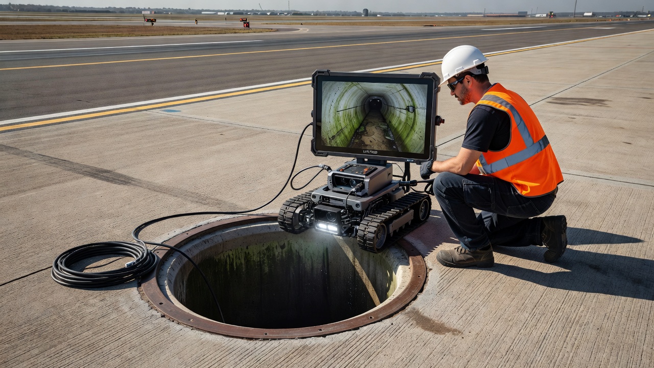
The most effective method for identifying and locating blockages is CCTV drain inspection, where a remote-controlled camera is inserted into the pipe through a cleanout or the outlet, and the pipe interior is inspected along its entire length. CCTV footage reveals the location, nature, and severity of obstructions, informing the maintenance response.
Rodent damage is a surprisingly common and serious problem in pavement drainage systems. Rats, mice, and other burrowing animals enter drainage pipes through outlets and cleanouts, building nests that can completely block the pipe cross-section and prevent water flow. Rodent nests consist of organic material — leaves, grass, paper, and soil — bound together with urine and feces, creating a dense mass that is difficult to flush out.
Rodent damage also extends to structural damage: rodents gnaw on PVC and HDPE pipes, creating openings through which soil can enter and additional rodents can access the system. In severe infestations, rodent activity can undermine the pavement edge by creating voids in the subgrade adjacent to the drain trench.
The presence of rodents is indicated by droppings at outlets, evidence of burrowing at the outlet apron, distinctive musty odors from nest material, and vegetation disturbance along the drain line. Rodent entry points must be sealed with flap gates, wire mesh screens, or one-way valves that allow water to exit but prevent animal entry.
Erosion at drainage outlets indicates that discharge velocities are exceeding the erosion resistance of the receiving channel. The inspector checks for: scour holes below the outlet pipe, undercutting of the headwall or apron, deposition of eroded material downstream, and widening or deepening of the ditch channel below the outlet.
Outlet erosion can progress rapidly during heavy rainfall events when drainage flows are highest. Once erosion begins, it accelerates: the scour hole deepens, reducing outlet clearance, creating a hydraulic drop that increases flow energy, which in turn increases erosion. If the outlet pipe becomes exposed above the eroded ditch bottom, it may be unsupported over a span, leading to pipe fracture.
Erosion repair involves regrading the ditch, placing appropriately sized riprap or concrete erosion protection, and potentially installing energy dissipation structures to reduce discharge velocity at the outlet.
When subsurface drainage systems fail to function, the pavement structure becomes a reservoir for trapped water. The consequences are progressive, cumulative, and ultimately catastrophic for pavement performance.
Pumping is the ejection of water and fine soil particles from beneath concrete pavement slabs under the action of traffic loading. When a heavy wheel load passes over a joint or crack, the concrete slab deflects downward, pressurizing water trapped in the pavement structure. The pressurized water flows laterally, carrying suspended fine particles — clay, silt, and fine sand — from the base and subgrade. When the wheel load passes, the slab rebounds, creating a suction that draws more water and fines into the void beneath the slab.
The visual evidence of pumping is a light-colored stain on the pavement surface at joints and cracks, extending onto the shoulder. The stain consists of the fine soil particles that have been transported from beneath the slab. In advanced cases, water may be seen visibly ejected from joints under passing traffic.
The major factors contributing to pumping, as documented in NCHRP Web Document 35-B, are: the presence of excess water in the pavement structure, erodible base or subgrade materials, and high volumes of high-speed heavy wheel loads. The damage from pumping is both immediate and progressive: each pumping event removes more material from beneath the slab, increasing the void space and allowing greater slab deflection under subsequent loads.
Faulting is the vertical displacement of adjacent concrete slabs at a joint, where the approach slab is higher than the leave slab. Faulting is the direct result of pumping: as fines are ejected from beneath the leave slab (the slab on the far side of the joint from the approaching traffic), a void develops. The leave slab loses support and settles under traffic loading, creating a step at the joint.
Faulting is measured in millimeters of vertical offset. A fault of 3 mm (1/8 inch) produces a noticeable bump for vehicle or aircraft traffic. Faults of 6 mm (1/4 inch) significantly increase dynamic loading, accelerating further deterioration. At 10 mm (3/8 inch) and above, faulting creates a safety hazard, particularly for aircraft where the impact can damage landing gear components.
Faulting propagates rapidly once initiated. Each vehicle passage increases the dynamic load at the faulted joint, which increases pumping at the joint, which accelerates material loss, which increases faulting. This positive feedback loop means that early intervention — before faulting exceeds 3 mm — is far more effective than attempting to repair advanced faulting.
Freeze-thaw damage in pavements occurs when water trapped within the pavement structure freezes and expands. The volume expansion of water upon freezing is approximately 9% , but the damaging potential is far greater because the expansion generates pressures exceeding 220 MPa (32,000 psi) when confined within pore spaces and cracks.
In the pavement structure, freeze-thaw damage manifests in three ways. First, D-cracking in concrete pavements: the aggregate particles near joints and cracks absorb water, which freezes and causes the aggregate to fracture from within. D-cracking progresses from the bottom of the slab upward, ultimately destroying the concrete integrity along the joint. Second, frost heave: the formation of ice lenses in frost-susceptible subgrade soils causes upward displacement of the pavement surface, creating bumps, cracks, and unevenness. Third, thaw weakening: when ice lenses in the subgrade melt in spring, the saturated soil has dramatically reduced bearing capacity — reductions of 50% or more are typical — making the pavement extremely vulnerable to damage under traffic loading.
The combination of frost heave and thaw weakening creates a one-two punch: frost heave damages the pavement structure during winter, and thaw weakening leaves it vulnerable to traffic damage during spring. Each freeze-thaw cycle ratchets the damage upward, with the number of cycles per year (not just the minimum temperature) being the critical factor.
Water is the enemy of subgrade performance. Subgrade soils are designed and compacted at a specific moisture content to achieve target density and strength. When water enters the subgrade after construction, it increases the moisture content above the optimum, reducing strength and stiffness.
For fine-grained soils (clays and silts), the strength reduction from saturation can be dramatic. The undrained shear strength of a saturated clay subgrade may be only 10% to 20% of its strength at optimum moisture content. This means that a pavement designed for thousands of load applications per day may fail after only hundreds — or fewer — if the subgrade becomes saturated.
For granular soils (sands and gravels), saturation reduces apparent cohesion to zero and can trigger internal erosion (suffusion) where fine particles are transported by flowing water, leaving behind a weakened soil structure. The modulus of a saturated granular subgrade can be reduced by 50% or more compared to the same material at optimum moisture conditions.
The mechanism of subgrade weakening is often invisible from the surface. A pavement may appear structurally sound while the subgrade beneath is progressively softening, losing support, and allowing excessive deflections that fatigue the surface layers. By the time distress appears at the surface, the subgrade damage is often severe and requires full-depth reconstruction to remediate.
Airport pavement drainage presents unique challenges that distinguish it from highway drainage. Aircraft wheel loads are substantially higher than highway truck loads: a Boeing 747-400 main gear tire load exceeds 22,000 kg (48,500 lbs), compared to approximately 9,000 kg (20,000 lbs) for a heavy truck. The consequences of pavement failure at an airport — including aircraft damage, runway closure, and safety incidents — are far more severe than for highway pavements.
The FAA Advisory Circular 150/5320-5D provides the governing standard for airport drainage design in the United States. The AC addresses both surface storm drainage and subsurface drainage for paved runways, taxiways, and aprons. Key requirements include: design for the appropriate return period storm (typically 5-year for airfield pavements, 10-year for critical infrastructure), load-bearing capacity for aircraft weighing up to 600,000 kg or more, and elimination of drainage features that could attract hazardous wildlife.
Wildlife hazard mitigation is a critical consideration unique to airport drainage design. The FAA requires that drainage features be designed to eliminate or mitigate features that could attract hazardous wildlife on or around airports. Standing water in ditches, detention basins, and outlet areas attracts birds, which pose a serious bird strike risk to aircraft. Drainage design must minimize ponding, provide steep side slopes that discourage wading birds, and incorporate covers or screens on outlet structures.
The FAA also restricts the height of any drainage structure located within a safety area to 75 mm (3 inches) or less above grade, as specified in 14 CFR Part 139. This includes outlet headwalls, cleanout covers, and access risers. Structures exceeding this height present a collision hazard to aircraft that may inadvertently leave the paved surface.
Airport pavement subsurface drainage typically incorporates redundant systems, with both edge drains and permeable bases installed as standard practice. The FAA recommends monitoring systems to ensure continual function of drain systems, particularly where pavements are constructed below the permanent or seasonally high water table. Redundancy is essential because the consequences of drainage failure at an airport — including the potential for aircraft damage and runway closure — are unacceptable.
High-traffic airport pavements, particularly main runways serving commercial aviation, are typically designed with daylighted permeable bases where the permeable layer extends to the embankment slope without collector pipes. This design approach, endorsed by FAA standards, eliminates the risk of pipe blockage and simplifies maintenance. The daylighted base edge is sloped at 3% toward the ditch, with the bottom of the exposed edge at least 150 mm (6 inches) above the 10-year storm flow line.
CCTV (Closed-Circuit Television) drain inspection is the most effective method for assessing the internal condition of subsurface drainage pipes. A remote-controlled camera unit is inserted into the pipe through a cleanout or outlet and traverses the pipe length while transmitting real-time video to an operator at the surface.
The CCTV inspection equipment consists of a crawler unit with rubber tracks or wheels, a high-definition camera head with pan-and-tilt capability, and a lighting system for illumination in the dark pipe interior. The camera head can rotate 360 degrees and tilt to view pipe joints, perforations, and side connections from any angle. Advanced units incorporate laser profiling to measure pipe cross-section geometry and detect deformation or ovality.
CCTV inspections identify multiple categories of defects: structural defects including cracks, fractures, collapsed sections, joint displacement, and pipe deformation; hydraulic defects including sediment deposits, blockages, root intrusion, and debris accumulation; and maintenance defects including missing or damaged cleanout covers, exposed pipe at outlets, and evidence of rodent activity.
The inspection is conducted systematically, with the camera moving at a steady speed of 5 m to 10 m per minute (15 to 30 ft per minute), pausing at each joint and at any defect location for detailed recording. The pipe run is measured and defects are logged with their chainage (distance from the insertion point) for precise location. The video footage is recorded and retained as a permanent record of pipe condition.
CCTV drain surveys should be conducted annually as part of a preventive maintenance program for major pavement drainage systems. Additional inspections are warranted after significant storm events, after construction activity adjacent to drainage lines, and whenever surface evidence suggests drainage impairment. The cost of a CCTV survey is typically a small fraction of the cost of repairing a failed drainage system — and an even smaller fraction of the cost of reconstructing a pavement that has failed due to drainage problems.
| Defect Type | Examples | Severity Indicators | Maintenance Response |
|---|---|---|---|
| Structural | Cracks, fractures, collapsed sections | Crack width > 3 mm, visible soil entry | Pipe replacement or lining |
| Hydraulic | Sediment, blockages, root intrusion | Flow area reduction > 20% | Flushing, root cutting, jetting |
| Maintenance | Damaged cleanout, exposed pipe, rodent signs | Missing cover, > 300 mm exposed pipe | Repair cover, seal outlet, backfill |
| Joint Defects | Open joints, displaced joints, infiltration | Gap > 5 mm, visible soil entry | Joint repair or pipe replacement |
Flushing is the primary maintenance operation for subsurface drainage pipes. The process involves introducing water at high velocity into the pipe to remove sediment, debris, and organic matter that has accumulated on the pipe invert. Flushing restores the pipe cross-section to its full flow capacity and extends the interval between more intensive cleaning operations.
Flushing may be performed unidirectional (water introduced at the upstream cleanout and discharged at the outlet) or bidirectional (water introduced simultaneously from both ends to mobilize stubborn deposits). The flushing velocity should be sufficient to transport the accumulated sediment — typically 0.6 m/s to 1.5 m/s (2 to 5 ft/s) depending on particle size and density. Higher velocities, up to 3 m/s (10 ft/s), may be required for consolidated or clay-rich sediment.
The flushing water source should be clean to prevent introducing additional sediment. For airport pavements, water quality is important: flushing discharge must be collected and treated if it contains fuel residues, deicing chemicals, or other pollutants that may have accumulated in the drainage system.
The frequency of flushing depends on the sediment accumulation rate, which is influenced by the catchment soil type, pavement condition, and climate. Annual flushing is typical for most systems, with more frequent flushing for systems in areas with erodible soils or heavy sediment loads from pavement surface runoff.
Rodent exclusion is a critical but often overlooked maintenance activity. Rats and mice can enter drainage pipes through outlets that lack protection, through damaged pipe sections, or through cleanout covers that are missing or improperly sealed. Once inside, they build nests that block the pipe, create structural damage through gnawing, and introduce organic material that accelerates sediment accumulation.
The most effective rodent exclusion measure is the installation of flap gates or one-way valves at outlet pipe ends. These devices allow water to flow out of the pipe but prevent animals from entering. The flap is hinged at the top of the pipe and swings open under the pressure of outgoing water, then closes by gravity when flow stops. Flap gates must be inspected regularly to ensure they are not jammed open by debris or corroded in the open position.
For cleanouts, threaded or bolted covers with gaskets provide a rodent-proof seal. The cover must be securely fastened at all times except when the cleanout is in active use. Any covers found loose or missing during inspection should be immediately replaced.
In cases of established rodent infestation, a drain survey should be conducted to identify entry points, nesting locations, and the extent of damage. Removal of nest material by flushing or rodding must be followed by sealing of all entry points to prevent re-infestation. Poison bait stations placed at outlets (where approved and environmentally appropriate) can help control rodent populations.
The relationship between drainage condition and pavement life is well established through decades of performance studies. FHWA Demonstration Project 87 documented that pavements with effective subsurface drainage can achieve 30% to 100% longer service life than equivalent undrained pavements. AASHTO design procedures explicitly recognize this benefit through drainage modification factors that increase the effective structural capacity of drained pavements.
The mechanism of life extension is straightforward: water accelerates every significant pavement distress mechanism. By removing water within hours rather than allowing it to remain for days or weeks, subsurface drainage reduces the time available for pumping, erosion, stripping, freeze-thaw damage, and subgrade weakening to occur. The pavement spends more of its life in a dry, structurally competent state.
The economic case for subsurface drainage is equally compelling. The incremental cost of adding subsurface drainage to a new pavement — typically 10% to 20% of the pavement construction cost according to FHWA surveys — is far less than the cost of premature pavement failure. A pavement that fails 10 years early due to poor drainage must be reconstructed at 100% of new construction cost, with additional costs for traffic disruption, user delays, and (for airports) operational impacts.
For existing pavements, retrofit drainage — installing edge drains and daylighting permeable bases in pavements that were originally built without subsurface drainage — can extend remaining service life by 5 to 15 years. Retrofit drainage is one of the most cost-effective pavement rehabilitation strategies available, particularly for concrete pavements where pumping and faulting are the primary distress mechanisms.
The AASHTO Mechanistic-Empirical Pavement Design Guide (MEPDG) explicitly accounts for drainage quality in performance predictions. A pavement with “excellent” drainage (time-to-drain less than 2 hours) is predicted to develop distress at a significantly slower rate than an otherwise identical pavement with “poor” drainage (time-to-drain greater than 1 month). The MEPDG considers drainage condition in its prediction of fatigue cracking, faulting, and roughness progression.
The design and management of subsurface drainage systems requires an integrated approach combining proper design and construction with regular inspection and proactive maintenance. Drainage systems that are “designed and forgotten” inevitably fail — and take the pavement structure with them. The most successful pavement agencies treat subsurface drainage as an active system requiring ongoing attention throughout the pavement life cycle, allocating resources for annual inspection, periodic cleaning, and timely repair.
For airport pavements specifically, the FAA’s emphasis on drainage in AC 150/5320-5D reflects the critical importance of subsurface water management for operational safety and infrastructure longevity. The combination of high loads, high frequency operations, and strict safety requirements makes airport pavements particularly dependent on effective drainage. A well-maintained subsurface drainage system is the single most cost-effective investment in extending airport pavement life and ensuring safe, uninterrupted aircraft operations.
Ensure your airport or highway pavement drainage systems are designed, inspected, and maintained to the highest standards. Our engineering experts deliver comprehensive drainage solutions that extend pavement life and ensure operational safety.
Edge drains are longitudinal subsurface drains installed along pavement edges to intercept and remove water from the pavement structure, preventing water-relate...
A drain in airport infrastructure is an engineered system for the removal of surface and subsurface water from paved areas such as runways, taxiways, and aprons...
The subgrade is the prepared and compacted native soil or improved earth that forms the foundation of a pavement structure. Subgrade strength and uniformity dir...