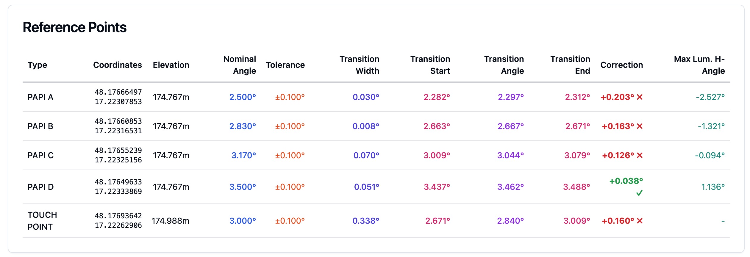
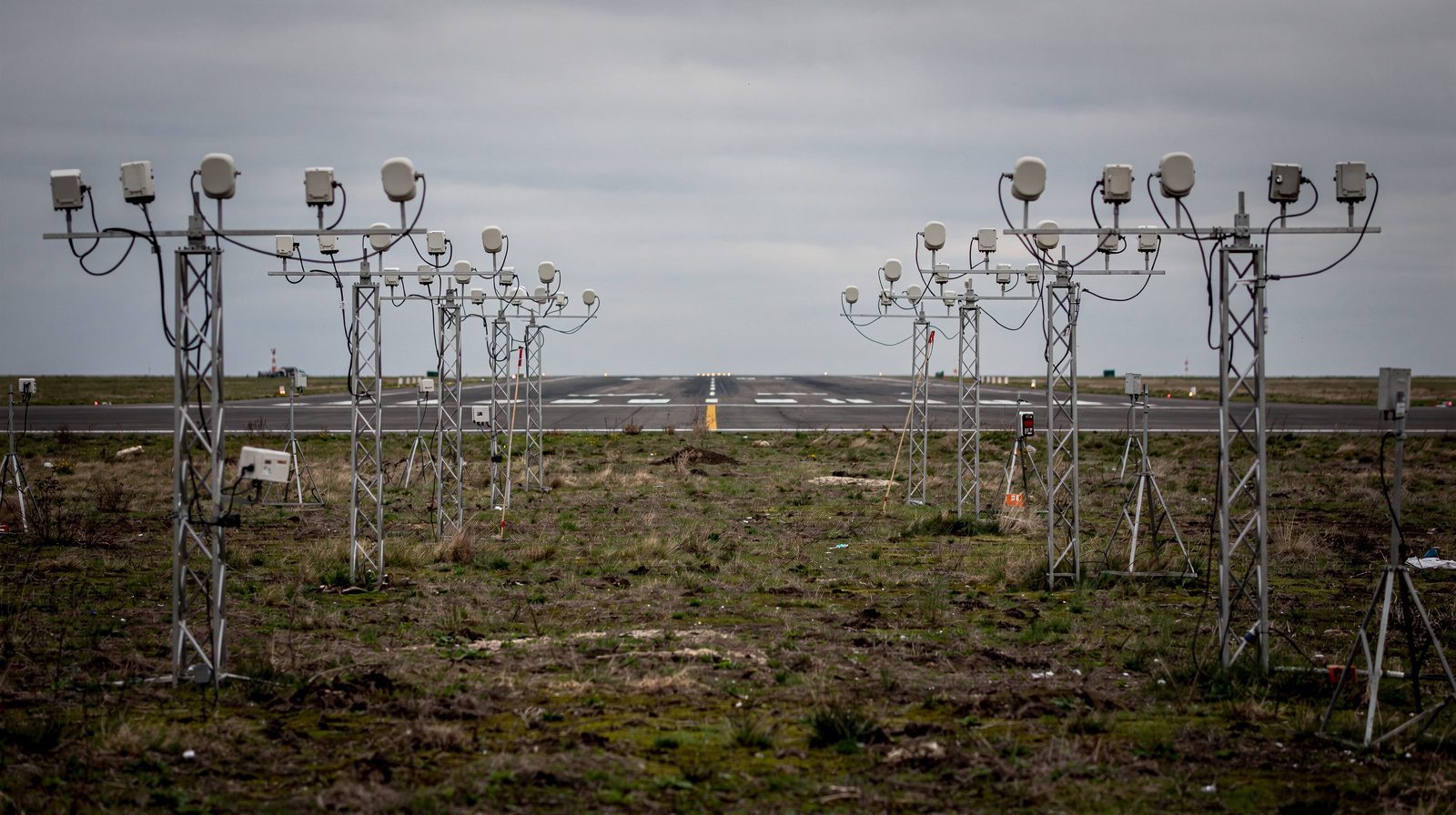
What is the Visual Approach Slope Indicator (VASI)?
Visual Approach Slope Indicator (VASI)
Definition and Purpose
The Visual Approach Slope Indicator (VASI) is a standardized visual aid system installed near the thresholds of airport runways. Its primary function is to provide pilots with clear, instantaneous visual guidance on their approach angle during the final stages of landing. VASI systems use color-coded lights, mainly red and white, to indicate whether an aircraft is above, on, or below the optimal glide path. Positioned typically beside the runway threshold, VASI ensures a stable descent, improves obstacle clearance, and aids correct runway alignment. According to ICAO Annex 14 and FAA standards, VASI must be visible from at least 3–5 miles by day and up to 20 miles by night, making it indispensable for landings in low-visibility or non-instrument conditions.
VASIs are engineered to strict international standards, ensuring that pilots worldwide can rely on consistent cues when transitioning from instrument to visual flight. The system’s simple logic, summed up in mnemonics like “Red over white, you’re all right”, makes it highly effective for both experienced and student pilots. VASI not only supplements instrument landing systems (ILS) but also acts as a primary aid at airports lacking advanced navigation equipment.
System Components and Operational Principles
A typical VASI installation consists of one or more bars of light units, each containing several lamps with optical filters and lenses. These units are precisely aligned to project a distinct horizontal color split, white above, red below. When an aircraft is on the correct glide path (usually 3°), the pilot sees the near bar as white and the far bar as red. Deviations above or below this path change the visible color pattern, providing immediate feedback.
- Two-bar VASI: Most common, with a near and far bar.
- Three-bar VASI: Adds a middle bar for high-cockpit (large) aircraft.
- Tri-color and Pulsating VASI: Compact or special-use variants.
VASIs are elevated above ground level to minimize interference. Their orientation and the sharpness of the color transition (within 3 arcminutes) are critical for accuracy. The system is regularly calibrated for photometric and geometric precision as per ICAO and FAA requirements. Many VASIs can be activated remotely via Pilot Controlled Lighting (PCL) at non-towered airports.
Types of VASI Systems
Two-Bar VASI
The two-bar VASI features two parallel light bars. Each bar’s elevation angle is precisely set so that:
| Near Bar | Far Bar | Meaning |
|---|---|---|
| White | White | Too high |
| White | Red | On glide path |
| Red | Red | Too low |
The standard approach angle is 3°, but may vary based on terrain or obstacles. Two-bar VASIs are ideal for general aviation airports, training fields, and regional airfields.
Mnemonic aids:
- “Red over white, you’re all right.”
- “Red over red, you’re dead.”
- “White over white, fly all night.”
Three-Bar VASI (Dual VASI)
The three-bar VASI introduces a middle bar, providing dual glide paths:
| Bars Used | Glide Path | Aircraft Type |
|---|---|---|
| Near + Middle | Standard (3°) | Light/medium aircraft |
| Middle + Far | Higher (~3.25°) | Large/high-cockpit jets |
This ensures that both small and large aircraft receive appropriate guidance, reducing risk of undershoots or tail strikes for long-bodied jets.
Tri-Color VASI
The Tri-Color VASI uses a single optical unit projecting:
| Color | Position |
|---|---|
| Red | Too low |
| Green | On glide path |
| Amber | Too high |
Range is shorter (0.5–1 mile by day, 5 miles by night). Often installed at small airports or heliports.
Pulsating VASI (PVASI)
PVASI uses pulsating lights for additional clarity:
| Signal | Meaning |
|---|---|
| Pulsating white | Well above glide path |
| Steady white | On glide path |
| Steady red | Slightly below glide path |
| Pulsating red | Well below glide path |
PVASI is especially useful in challenging terrain or where compactness is needed.
T-VASIS and AT-VASIS
- T-VASIS: Advanced system with 20 light boxes in a “T” shape for precise guidance, favored at major international airports.
- AT-VASIS: Simplified version for smaller facilities.
Technical Standards and Regulatory Framework
VASI systems are governed by ICAO Annex 14 and FAA standards:
- Glide Path Angle: Usually 3°, adjustable for local conditions.
- Light Performance: Must be visible from 3–5 miles (day) and 20 miles (night).
- Coverage: ±10° from runway centerline, up to 4 NM from threshold.
- Maintenance: Regular calibration and inspection of photometric and geometric properties.
- Documentation: Any operational changes are published via NOTAMs and in AIPs.
Key references:
- ICAO Annex 14, Volume I
- FAA AIM, Section 2-1-2
- FAA AC 150/5345-28
VASI vs. PAPI: Comparison Table
| Feature | VASI | PAPI |
|---|---|---|
| Light Arrangement | Two/three bars, parallel rows | Four (or two) lights, single row |
| Guidance States | Three (high/path/low) | Five (far high, slightly high, path, slightly low, far low) |
| Glide Path Precision | Lower | Higher |
| Installation | Usually left side, sometimes both | Usually left side, single row |
| Coverage | 4 NM, ±10° lateral | 3.4 NM, ±10° lateral |
| Cost/Maintenance | Lower | Higher |
| Use Case | Small/medium airports, training | Large/busy airports, precise approaches |
| Status | Being phased out for PAPI | Modern standard |
Use Cases and Operational Applications
For Pilots
- Landing Guidance: Maintains stable approach, increasing landing safety.
- Training: Offers clear, memorable cues for student pilots.
- Large Aircraft: Three-bar systems prevent tail strikes for jets.
For Airport Operators
- Two-bar VASI: For straightforward approaches and lighter aircraft.
- Three-bar VASI: For airports with mixed or heavy jet traffic.
- Tri-color/Pulsating: For heliports or space-limited locations.
- Maintenance: LED upgrades reduce costs and increase reliability.
Mnemonics and Pilot Memory Aids
- “Red over white, you’re all right.”
- “Red over red, you’re dead.”
- “White over white, fly all night.”
- Tri-color: Red = climb, Green = maintain, Amber = descend.
Technical and Regulatory Notes
- Visibility: VASI brightness and color transitions are standardized for clarity.
- Pilot Controlled Lighting: Enables remote activation at non-towered airports.
- System Variants: T-VASIS and AT-VASIS provide enhanced guidance for complex operations.
- Obsolescence: Some older VASI types are being replaced with PAPI for higher precision, but many remain in use.
Visual References
Regulatory References and Further Reading
- ICAO Annex 14, Volume I: Aerodrome Design and Operations
- FAA Aeronautical Information Manual (AIM), Section 2-1-2
- FAA Pilot’s Handbook of Aeronautical Knowledge (PHAK)
- FAA AC 150/5345-28: PAPI Systems
- CFI Notebook – Visual Glide Slope Indicators
- Pilot Institute – VASI vs. PAPI Differences
For detailed technical diagrams, refer to official ICAO and FAA publications or airport-specific charts.
Frequently Asked Questions
- How does a VASI system work?
- A VASI system consists of light bars (typically two or three), each with red and white lights. The color combination seen by the pilot (e.g., red over white) instantly indicates if the aircraft is above, on, or below the ideal glide path.
- What’s the difference between VASI and PAPI?
- VASI uses horizontal bars of lights and provides three guidance states (too high, on path, too low). PAPI uses a row of four lights and offers more precise guidance with five states, making it preferred at busy or international airports.
- Where is VASI installed on the runway?
- VASI bars are positioned beside the runway threshold, typically on the left side, at precisely calculated distances to provide accurate glide slope guidance within ±10° of the extended runway centerline and up to 4 nautical miles from threshold.
- Are VASI systems still used?
- While many airports are upgrading to PAPIs, VASI systems remain in use worldwide, especially at regional, training, and some international airports, due to their simplicity, reliability, and cost-effectiveness.
- What does ‘Red over red, you’re dead’ mean?
- This pilot mnemonic means that if you see red lights on both VASI bars, your approach is too low, posing a risk of undershooting the runway. Pilots should adjust to achieve the ‘red over white’ (on path) indication.
This is a reference entry. TarmacView provides drone inspection services and doesn't sell the equipment or materials described in this glossary.