What is a Visual Glide Slope Indicator (VGSI)?
VGSI – Visual Glide Slope Indicator (Airport Lighting)
Definition
A Visual Glide Slope Indicator (VGSI) is a ground-based airport lighting system that provides pilots with instantaneous, visual descent guidance during final approach and landing. By projecting color-coded lights visible from miles away, VGSIs allow pilots to quickly judge their vertical position relative to the optimal glide path for a specific runway. These systems are vital for maintaining clearance over obstacles and ensuring aircraft reach the runway threshold at the proper touchdown angle.
VGSIs do not offer lateral (side-to-side) guidance, but are strictly vertical navigation aids. They are found at a wide range of airports, from small general aviation strips to major international hubs, and often supplement electronic aids such as the Instrument Landing System (ILS). VGSI systems are internationally standardized by organizations like ICAO (Annex 14) and national regulators (e.g., FAA).
The system works by projecting beams with abrupt color transitions (typically red and white), so pilots see different color patterns depending on their vertical position. This visual cueing allows for immediate corrections, enhancing runway safety and reducing incidents of controlled flight into terrain or runway overruns.
Purpose and Importance
Safety
The primary purpose of a VGSI is to give pilots a clear, visual signal of their position relative to the prescribed glide slope during approach. By presenting unambiguous color patterns, VGSIs support stabilized approaches, the key to safe landings and to minimizing approach and landing accidents, statistically the most hazardous flight phase.
Safety enhancement is central: VGSIs provide standardized glide path cues, enabling consistent approaches at any airport or in any weather and light condition. They are especially critical when visual references to terrain or runway are degraded, by haze, precipitation, or nighttime operations. Proper VGSI guidance ensures pilots maintain minimum clearance over obstacles and land in the correct runway zone.
Regulation
Civil aviation authorities (FAA, EASA, ICAO) specify VGSI installation and operational standards. For example, the FAA requires VGSIs on runways used by turbojets or where approach guidance is needed. ICAO mandates VGSIs on all precision approach runways unless equivalent safety is provided. Regulations require pilots to maintain the VGSI glide path unless a different altitude is needed for safety.
Training
VGSIs are essential in pilot training, reinforcing visual judgment and approach path control. For students and those transitioning to new aircraft or airports, VGSIs provide an objective standard for safe approaches.
In summary:
VGSIs are not just visual aids, but crucial safety systems supporting the operational integrity of runway approaches worldwide.
Major Types of VGSI Systems
1. Visual Approach Slope Indicator (VASI)
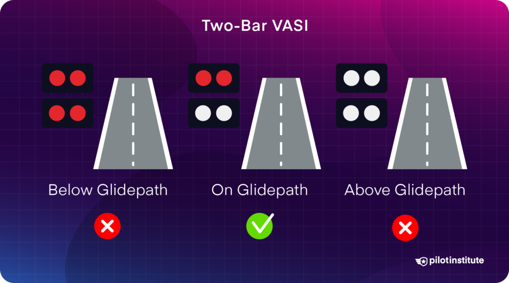
VASI is one of the earliest and most widely used VGSI systems. It uses pairs of light bars (near and far) perpendicular to the runway centerline. Each bar has multiple lights projecting sharply divided red (lower) and white (upper) beams. The pilot’s view of the color depends on their vertical position.
Structure and Layout
- Two-bar VASI: Near and far bars, provides three-state guidance (above, on, or below glide path).
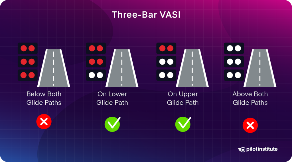
- Three-bar VASI: Adds a middle bar for large aircraft, creating two separate glide paths (upper for large, lower for small aircraft).
- Tri-color VASI: (less common) Shows red, green, or amber, offering a compact indication for small airports.
The bars’ placement is engineered so the color transition occurs precisely at the intended glide path angle, accounting for runway elevation and obstacles.
Principle of Operation
- Above glide path: Both bars appear white.
- On glide path: Near bar is white, far bar is red.
- Below glide path: Both bars appear red.
Three-bar VASI:
- Large aircraft use middle/far bars, small aircraft use near/middle bars due to cockpit height.
Indications and Mnemonics
| Near Bar / Far Bar | Indication | Mnemonic (“Red over white, you’re all right”) |
|---|---|---|
| White / White | Too high | “White over white, fly all night.” (Too high) |
| White / Red | On glide path | “Red over white, you’re all right.” |
| Red / Red | Too low | “Red over red, you’re dead.” (Immediate climb) |
Coverage
- Day: ≥3 miles visible (ICAO: 5 km/2.7 NM).
- Night: Up to 20 miles.
- Sector: ±10° of runway centerline, 4 NM from threshold.
- Glide path angle: Usually 3.0°, up to 4.5° for obstacles.
Example
A VASI-equipped regional airport allows both trainers and airliners to approach safely, with each using the appropriate bars for their cockpit height.
Safety Notes
- Indications valid only on runway centerline sector.
- “Red over red” requires immediate climb.
- VASI does not account for displaced thresholds unless calibrated.
Reference Diagrams
2. Precision Approach Path Indicator (PAPI)
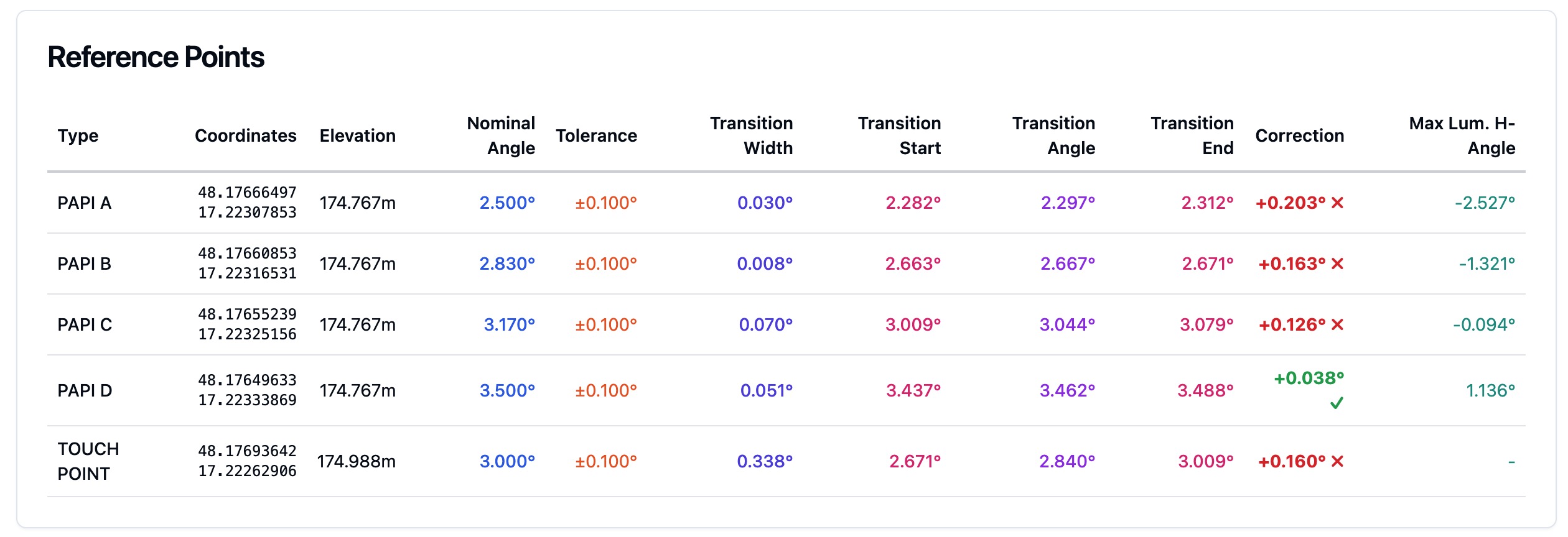
PAPI is the current ICAO and FAA standard, offering finer resolution than VASI. It consists of four (sometimes two) light units in a row, typically on the runway’s left side. Each light is calibrated to show red or white at a specific angle.
Structure and Layout
- Standard: Four lights, 250–400 ft from threshold, 50–200 ft from edge.
- Abbreviated: Two lights (for smaller airports).
Principle of Operation
- 4 white: Much too high.
- 3 white/1 red: Slightly high.
- 2 white/2 red: On glide path.
- 1 white/3 red: Slightly low.
- 4 red: Much too low.
This allows for smaller, more precise corrections than VASI.
Indications and Mnemonics
| Display | Glide Path Status | Meaning |
|---|---|---|
| 4 White | Too high | Descend to recapture path |
| 3 White, 1 Red | Slightly high | Descend slightly |
| 2 White, 2 Red | On glide path | Continue approach |
| 1 White, 3 Red | Slightly low | Climb slightly |
| 4 Red | Too low | Climb immediately |
Mnemonic:
“Red over white, you’re all right.”
“Four red, you’re dead.”
“White on right, high as a kite.”
Coverage
- Day: ≥5 miles
- Night: Up to 20 miles
- Sector: ±10° of centerline, 3.4 NM from PAPI
- Glide angle: 3.0° standard (can be steeper for obstacles)
Example
A Boeing 777 approaches Heathrow, using the PAPI’s “two red, two white” to confirm a safe glide path.
Safety Notes
- PAPI is more precise than VASI, ideal for large jets.
- Four red or four white require immediate correction.
- Indications valid only on centerline sector, always check approach charts.
Reference Diagram

3. Pulsating Light Approach Slope Indicator (PLASI)
PLASI is a compact, single-unit VGSI, popular at small airports with limited space or budget. It emits steady or pulsating red/white lights. The pulse rate and color tell pilots their glide path position.
Structure and Layout
- Single light unit: Near the touchdown zone, aligned with or offset from the centerline.
Principle of Operation
- Steady white: On glide path.
- Pulsating white: Above glide path (pulse rate increases with height).
- Steady red: Slightly below glide path.
- Pulsating red: Well below glide path (pulse rate increases with deviation).
Indications and Mnemonics
| PLASI Signal | Glide Path Status | Action |
|---|---|---|
| Steady white | On path | Continue approach |
| Pulsating white | Above path | Descend |
| Steady red | Slightly low | Climb slightly |
| Pulsating red | Well below | Climb immediately |
Mnemonic:
“Steady white: just right. Steady red: slightly low. Pulsing red: well below, climb.”
Coverage
- Day: 5 miles
- Night: 20 miles
- Best for: Small/GA airports or limited-infrastructure sites.
Example
A Piper Archer at a rural field sees steady red, climbs slightly to return to the glide path.
Safety Notes
- The steady white sector is narrow, requiring precise approach.
- Pulsating red means dangerously low, climb immediately.
Reference
PLASI System at Cameron Park Airport
Regulatory Standards
ICAO Annex 14
- Sets global specifications for VGSI installation, color coding, beam angles, and obstacle clearance.
- Minimum obstacle clearance: 3 meters (10 ft) at threshold, 4 meters (13 ft) elsewhere.
FAA AC 150/5345-28G
- Details U.S. standards for VGSI design, intensity, and maintenance.
- Specifies required use on commercial and turbojet runways.
EASA/Other Regions
- Adopt ICAO standards, with local adaptation for terrain, climate, or airfield layout.
Pilot Procedures
- Always check airport charts for VGSI type and glide angle.
- VGSI indications are valid only in the approach sector (±10° of centerline).
- Under instrument conditions, follow electronic glide path (e.g., ILS) if available.
- If VGSI and electronic indications disagree, prioritize instrument guidance in IMC.
Summary Table: VASI vs. PAPI vs. PLASI
| System | Structure | Indications | Coverage | Use Case |
|---|---|---|---|---|
| VASI | 2–3 bars, red/white lights | White/Red combinations | 3–5 mi day, 20 mi night | Small to medium airports |
| PAPI | 4 aligned lights | 4/3/2/1/0 red/white mix | 5 mi day, 20 mi night | Commercial, high-traffic |
| PLASI | Single unit, pulsing light | Steady/Pulsating Red/White | 5 mi day, 20 mi night | Small, budget/space-limited |
Memory Aids
- “Red over white, you’re all right.”
- “Four red, you’re dead.”
- “Pulsing means you need to correct.”
Further Reading
VGSIs are a vital part of modern airport infrastructure, directly supporting safe, stabilized approaches and reducing accident risk. Their standardized, instantly recognizable visual guidance is indispensable to pilots worldwide, regardless of experience or aircraft type.
Frequently Asked Questions
- What is the main purpose of a VGSI at airports?
- A VGSI provides visual descent guidance to pilots on final approach, ensuring they maintain the correct glide path angle to the runway, avoid obstacles, and achieve safer, more stabilized landings.
- What are the main types of VGSI systems?
- The primary VGSI types are VASI (Visual Approach Slope Indicator), PAPI (Precision Approach Path Indicator), and PLASI (Pulsating Light Approach Slope Indicator). Each uses color-coded lights to show if an aircraft is above, on, or below the ideal glide path.
- How do pilots interpret VASI or PAPI light signals?
- Both VASI and PAPI display combinations of red and white lights. 'Red over white' or 'two red, two white' means on the correct path. More white means too high, more red means too low. Pilots adjust their approach based on these signals.
- Are VGSIs mandatory at all airports?
- Not all airports require VGSIs, but ICAO and FAA regulations mandate them on many precision approach runways, especially those serving commercial or turbojet aircraft. Some smaller or private fields may not have VGSI systems.
- How is a VGSI system different from an Instrument Landing System (ILS)?
- A VGSI provides visual-only vertical approach guidance using lights, while an ILS is an electronic system offering both lateral and vertical guidance for instrument approaches in low visibility.
This is a reference entry. TarmacView provides drone inspection services and doesn't sell the equipment or materials described in this glossary.