Bridge Deck
The bridge deck is the uppermost structural element of a bridge, directly supporting traffic loads and providing the riding surface. Deck condition — cracking, ...
34 min read
Bridges
Bridge Inspection
+3
Bridge deck waterproofing membranes are impermeable layers applied between the structural concrete deck and the asphalt wearing surface to prevent water and chloride penetration, protecting the deck and reinforcement from corrosion. Membrane failure leads to deck deterioration. Covers liquid-applied and sheet membrane systems, application, and inspection for membrane integrity.
A waterproofing membrane for bridge decks is a continuous impermeable barrier installed between the structural bridge deck — typically constructed of reinforced concrete, though steel orthotropic decks also require protection — and the asphalt or concrete wearing course that carries traffic. The membrane’s fundamental purpose is to prevent water, de-icing salts (chlorides), atmospheric pollutants, and other corrosive agents from penetrating the bridge deck structure. Without effective waterproofing, these agents reach the reinforcing steel in concrete decks, initiating electrochemical corrosion that produces expansive iron oxides. These corrosion products occupy 2 to 6 times the volume of the original steel reinforcement, generating tensile stresses that crack and spall the concrete cover, progressively destroying the structural integrity of the deck.
Bridge decks are the most vulnerable structural element of a bridge because they are directly exposed to traffic loads, de-icing chemicals, precipitation, freeze-thaw cycling, and UV radiation. The wearing course (asphalt or concrete overlay) alone does not provide adequate waterproofing — bituminous road surfacing materials are sufficiently permeable to allow water migration, as explicitly stated in Transport Infrastructure Ireland’s Standard DN-STR-03009. The waterproofing membrane serves as the primary line of defense, intercepting water and chlorides before they can reach the structural deck.
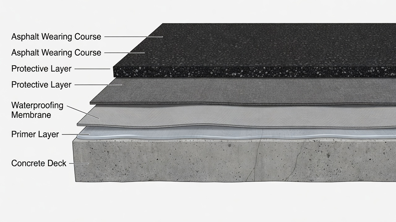
The typical bridge deck buildup consists of, from bottom to top: the structural concrete (or steel) deck; a primer layer (typically epoxy or bituminous) to promote adhesion and seal the substrate; the waterproofing membrane itself (liquid-applied or sheet); a protective layer (in some systems) to shield the membrane during construction; a tack coat or adhesion promoter to bond the overlay; and the asphalt wearing course (typically 50-100 mm of hot mix asphalt). The membrane must be compatible with each adjacent layer and withstand the high temperatures of hot-mix asphalt placement, which range from 160°C to 180°C (320°F to 356°F) depending on the binder grade and mix type.
The design life of a waterproofing system is a critical specification parameter. TII DN-STR-03012 (Design for Durability) requires that the waterproofing system design life be specified and achieved through proper material selection, application quality control, and protection during construction. A well-designed and properly installed waterproofing system should achieve a service life of 15 to 25 years before requiring replacement, depending on environmental exposure, traffic loading, and maintenance quality. The service life extension provided by effective waterproofing is one of the most cost-effective investments in bridge infrastructure preservation, with life-cycle cost analyses consistently demonstrating that waterproofing investment pays for itself many times over through deferred major rehabilitation and reconstruction.
Liquid-applied waterproofing membranes are materials applied in liquid form that cure through chemical reaction or solvent evaporation to form a continuous, seamless, monolithic elastomeric barrier on the bridge deck surface. They are applied by spray, roller, or squeegee in one or multiple coats to achieve the specified dry film thickness. The three principal liquid-applied membrane chemistries used in bridge deck waterproofing are polyurethane (PU), methyl methacrylate (MMA), and epoxy-based systems.
Polyurethane-based liquid-applied membranes are the most widely specified category for bridge deck waterproofing, combining high flexibility, excellent adhesion, rapid cure, and proven long-term durability. Sika’s Sikalastic product line exemplifies this category, with systems such as Sikalastic Bridge 5000 having a 20+ year track record of use on bridge decks worldwide. The Sikalastic Bridge 5000 system comprises multiple layers: a primer with broadcast sand for adhesion, a fast-cure waterproofing membrane, an adhesion promoter with broadcast sand, and a tack coat to bond the asphalt overlay. The system provides excellent adhesion and shear resistance with asphalt pavement, with specific formulations designed for both horizontal and vertical surfaces.
Sikalastic M 851 is a hot-spray applied polyurethane membrane that can cover over 1,000 m² in a single shift depending on applicator equipment and experience, significantly reducing labor costs during installation. The Sikalastic Traffic 2304 system uses a hot-spray applied membrane M 811 with rapid curing — typically 10 to 20 seconds gel time — enabling minimal downtime and quick installation. This system complies with German TL/TP-ING Part 6 (formerly ZTV-BEL B 3) requirements for bridge deck waterproofing.
Polyurethane membranes offer exceptional crack-bridging capability — typically up to 2-3 mm for dynamic cracks and 5+ mm for static cracks — accommodating the structural movements, thermal expansion, and crack propagation that inevitably occur in concrete bridge decks. The high-performing liquid systems form a superior chemical bond between the substrate, membrane, tack coat, and asphalt surfacing. This chemical bond, versus the mechanical bond of sheet systems, promotes long-term performance even in extreme weather conditions. Once the multi-layer PU system is applied, on-the-spot quality assurance through tensile testing can be immediately performed on site to verify continuous coverage and adhesion resilience.
Methyl Methacrylate (MMA) waterproofing membranes are high-performance, rapid-curing systems that polymerize through chemical reaction between MMA resin and a catalyst (initiator). The Britdex MDP system from USL Structural Protection exemplifies a complete MMA system comprising up to three separate environmentally friendly layers, each offering different properties. The system provides a 100% effective seamless bridge deck waterproofing membrane with extreme durability and flexibility, suitable for application to a variety of surfaces and structures including bridges, cut-and-cover tunnels, and immersed tube tunnels. The rapid curing properties of each element allow substantial areas to be covered in short periods, making the system cost effective for projects requiring accelerated timelines.
The Matacryl system from FPT Infrastructure uses PUMA (polyurethane methyl methacrylate) and MMA resin technology. A critical advantage of this chemistry is interlayer chemical bonding through polymerization — open polymer chains in each layer fuse together chemically rather than relying on mechanical bond, tapes, or overlay weight for adhesion. Tests per ASTM D4541 (steel) and ASTM D7234 (concrete) routinely achieve bond strengths of 500 to over 1,000 psi (3.4 to 6.9 MPa) on steel, concrete, tile, FRP panels, and other sound substrates. This bond strength is significantly higher than many alternative systems. The MMA/PUMA technology also enables recoating and repair without full deck removal — worn or spalled wear layers can be removed and a new layer installed, chemically bonding to the original system. This extends the service life of the original waterproofing system and mitigates the cost of full bridge deck remediation.
MMA systems are particularly specified for projects requiring rapid return to service. The polymerization reaction is complete within 1-4 hours depending on temperature, allowing the bridge to be opened to traffic or overlaid with asphalt within a single road closure period. The systems also offer excellent crack-bridging properties and superior resistance to jet fuel, hydraulic fluid, and de-icing chemicals, making them preferred for airport bridge applications.
Epoxy-based waterproofing systems for bridge decks include both solvent-based and solvent-free formulations that cure through chemical cross-linking between epoxy resin and hardener. Epoxy membranes provide very high bond strength to concrete substrates (often exceeding 2.0 N/mm² / 290 psi), excellent chemical resistance, and low permeability. They are commonly used as the primer layer in multi-layer waterproofing systems — Sika’s bridge deck systems include G-type epoxy resins that provide improved blush resistance (extending the application window), over 20% CO₂ reduction through use of bio-polymers, and significantly increased performance through patented technology.
Epoxy-based waterproofing systems tend to be more rigid than polyurethane or MMA alternatives, with limited elongation at break (typically 20-50% elongation versus 200-600% for polyurethane). This rigidity makes them more suited to applications where structural movements are minimal, or as the primer/sealer layer in combination with a more flexible membrane. Epoxy resin waterproofing for buried concrete surfaces specified in TII CC-SPW-02000 requires two coats of epoxy resin for concrete pipes with diameter greater than 2 meters. The EOTA EAD 030675-00-0107 specification “Liquid applied bridge deck waterproofing kits” provides the European framework for testing and approving liquid-applied bridge deck waterproofing systems, including PU, MMA, and epoxy formulations, covering adhesion, crack-bridging, hot asphalt resistance, and aging performance.
Preformed sheet membranes are factory-manufactured rolls of waterproofing material delivered to site in specified dimensions (typically 1 m to 2 m width and 10 m to 20 m length rolls) and applied to the prepared deck surface through torching, self-adhesive backing, or mechanical fixing. The principal sheet membrane types for bridge deck waterproofing are APP-modified bitumen, SBS-modified bitumen, PVC, and cold-applied self-adhesive membranes.
APP (atactic polypropylene)-modified bitumen membranes are torch-applied sheets that meet the requirements of EN 14695:2010 (Reinforced bitumen sheets for concrete bridge deck waterproofing). EN 14695 specifies testing requirements including tensile strength, elongation at break, nail tear resistance, flexibility at low temperatures (-10°C to -20°C depending on grade), dimensional stability, resistance to hot asphalt (tested at 200°C for 30 minutes without damage), and resistance to fatigue from moving loads. The membrane is reinforced with a carrier material — typically polyester non-woven fabric (providing tensile strength and puncture resistance) or glass fiber mat (providing dimensional stability) — embedded between layers of modified bitumen.
Sika’s SikaShield bridge deck one-layer system comprises an epoxy primer and one layer of APP-modified bitumen membrane meeting EN 14695 and German ZTV-ING 6-1 requirements. The system offers improved adhesion between membrane and substrate, easy application, and cost-effectiveness. The SikaShield bridge deck two-layer system comprises an epoxy primer, one layer of SBS-modified bitumen, and one layer of APP-modified bitumen, meeting EN 14695 and Austrian RVS 15.03.12 requirements. The epoxy primer provides an extra layer of waterproofing and concrete protection. The two-layer system provides redundancy — if the first layer is damaged, the second layer maintains waterproofing integrity.
SBS (styrene-butadiene-styrene)-modified bitumen membranes offer superior low-temperature flexibility compared to APP membranes, remaining flexible at temperatures as low as -20°C. SBS modification imparts rubber-like elastic properties to the bitumen, improving resistance to thermal cracking and structural movement. SBS membranes are typically applied using torch-on methods or as self-adhesive sheets with a release liner. The SBS polymer creates a three-dimensional network within the bitumen that provides elasticity and recovery after deformation — a critical property for bridge decks subject to dynamic traffic loading and thermal cycling. Sika’s two-layer bridge deck system incorporates SBS-modified bitumen as the base layer for enhanced flexibility, with APP-modified bitumen as the upper layer for high-temperature resistance during asphalt overlay placement.
PVC (polyvinyl chloride) membranes for bridge deck waterproofing are preformed sheets of PVC compound, sometimes modified with coal tar or plasticizers, with chopped fiber filler for reinforcement. NCHRP Report 165 “Waterproof Membranes for Protection of Concrete Bridge Decks” documents the use of preformed sheets of coal tar-modified PVC with chopped fiber filler at 75 mils (1.9 mm) thickness. PVC membranes offer high mechanical strength, excellent chemical resistance, and good flexibility. The Protecto Wrap Bridge Deck 400 system uses a preformed membrane providing effective waterproofing, high mechanical strength, puncture resistance, and excellent chemical resistance and physical properties. PVC sheet membranes are typically loose-laid or partially bonded and require ballasting from the overlay to prevent displacement during construction or under traffic-induced vibration.
Cold-applied self-adhesive sheet membranes eliminate the need for torching, improving site safety and reducing the risk of fire during installation. Polyguard’s Cold Flex SA membrane is a 135-mil (3.4 mm) cold-applied sheet that forms a waterproof barrier by adhering directly to the prepared deck surface. Its puncture resistance, when paired with Polyguard’s Polyflow drain board, exceeds ASTM standards by 200% — providing superior protection against backfill damage and construction traffic. The membrane delivers tensile strength of 50 lbs/in (8.75 kN/m) and 20% elongation, allowing it to withstand the mechanical stresses typical of bridge decks. Cold-applied systems eliminate the need for hot materials, improving safety and efficiency during installation. The primary advantage is elimination of the hot works permit requirements that many jurisdictions (including New York City) mandate for torch-applied roofing and waterproofing systems, where general contractors must secure permits and hire fire watch supervisors — adding significant cost and schedule constraints to projects.
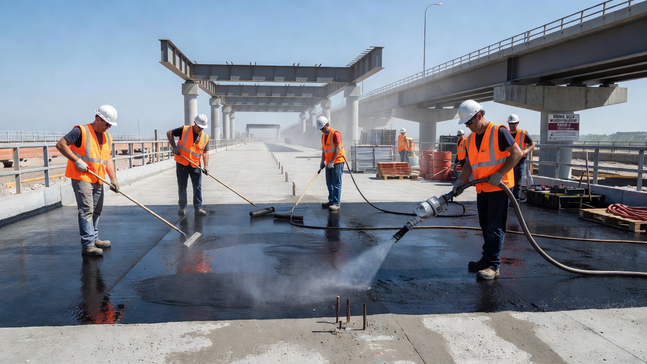
The success of any waterproofing system depends critically on proper installation procedures. The surface preparation requirements specified in TII DN-STR-03009 provide the benchmark for best practice. All unformed concrete surfaces receiving waterproofing must achieve Class U4 surface finish in accordance with the Specification for Road Works Series 1700 (Structural Concrete). Where the surface does not meet Class U4, repair work must be undertaken to achieve this classification. Formed concrete surfaces must be grit blasted to provide a lightly textured finish equivalent to U4. Freedom from laitance is essential to obtain sound adhesion of the waterproofing membrane to the deck. Grit blasting is the recommended surface preparation method; pressure washing is not recommended because of the additional time required for absorbed water to evaporate from the concrete. Curing liquids, compounds, and membranes can adversely affect adhesion and have restrictions on their use per CC-SPW-02000.
The Site Procedure Trial is a mandatory requirement per TII DN-STR-03009 Appendix C before any production waterproofing work commences. This trial verifies that the proposed waterproofing system, application equipment, surface preparation method, and applicator personnel can achieve the specified performance requirements including the minimum tensile bond strength of the waterproofing system. The use of a Permitted Waterproofing System (PWS) — one with a valid NSAI Agrément Certificate or equivalent — does not negate the need to verify adhesion compatibility with the specific deck concrete and surfacing materials.
Quality control during installation for liquid-applied membranes requires achieving uniform thickness across the entire deck surface. Dry film thickness (DFT) is measured using wet film gauges during application (wet film thickness converted to DFT using the solids content percentage) and confirmed using dry film thickness gauges on cured coating. Minimum DFT specifications for bridge deck membranes typically range from 1.5 mm to 3.0 mm depending on the system. For spray-applied polyurethane systems, the application equipment pumps the material at a controlled temperature (typically 60-80°C for hot-spray systems) and pressure to achieve the specified thickness in each pass. The operator must maintain consistent spray pattern, gun distance, and overlap to prevent thin spots.
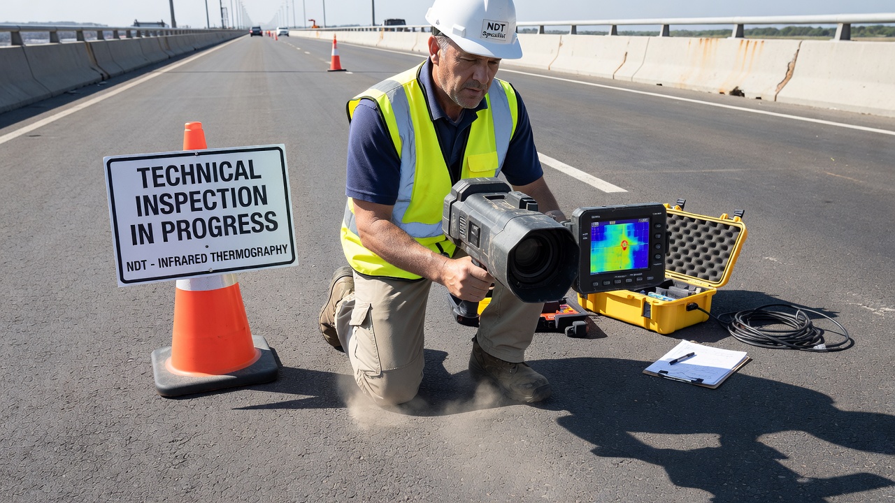
Post-application inspection before overlay placement should include: visual inspection of the entire membrane surface for blisters, pinholes, bare spots, tears, punctures, and edge lifting; adhesion testing in accordance with ASTM C1583 or equivalent using pull-off test equipment; and moisture testing to confirm the membrane is fully cured and moisture-free. Infrared thermography before overlay placement can detect voids, delamination, and moisture trapped beneath the membrane by measuring surface temperature differences during diurnal heating cycles. The BOND-TEST device per ASTM C1583 is specifically designed for field pull-off testing of waterproofing systems and concrete repairs.
Protection of the waterproofing during subsequent construction operations is specified in TII DN-STR-03009 Section 8. An Additional Protective Layer (APL) of sand asphalt or bituminous material complying with CC-SPW-02000 is required on specified areas to protect the membrane during surfacing and resurfacing operations. The protective layer must be laid by mechanical paver where possible — hand-laying of sand asphalt is strongly discouraged because of the difficulty achieving consistent thickness and compaction. For service bays, the waterproofing on the floor must always be protected.
Bond performance of the waterproofing membrane system operates on two interfaces: bond to the concrete deck substrate (substrate adhesion) and bond to the asphalt or concrete wearing course (interlayer adhesion). Both interfaces must meet minimum bond strength requirements to ensure the system performs as designed.
The bond to the concrete deck is the most critical interface because it prevents water migration along the plane between membrane and substrate. TII DN-STR-03009 specifies a minimum tensile bond strength of 1.0 N/mm² (145 psi) for the waterproofing system to the concrete substrate. This value is measured by pull-off testing in accordance with the Specification for Road Works. Bond failure at the concrete interface typically occurs through one of three mechanisms: adhesive failure at the membrane-primer or primer-concrete interface (indicating surface contamination or inadequate primer); cohesive failure within the concrete substrate (indicating weak concrete or laitance); or cohesive failure within the membrane layer (indicating inadequate cure or wrong thickness).
For liquid-applied polyurethane systems, the chemical bond to the concrete is achieved through the primer, which penetrates the concrete pores and provides a reactive surface for the membrane. Sika’s Sikalastic systems use epoxy primers that chemically react with both the concrete substrate and the polyurethane membrane layer. The chemical bond provided by liquid-applied systems is superior to the mechanical bond of sheet systems, which rely on the weight of the overlay and the adhesive properties of the bitumen to maintain contact with the deck.
The bond between the waterproofing membrane and the asphalt wearing course is equally critical. The wearing course must be sufficiently bonded to the membrane to resist shear stresses from braking and accelerating vehicles, thermal expansion and contraction movements, and the forces from asphalt compaction equipment. The shear resistance test evaluates this interface — Sika’s Sikalastic Bridge 5000 system is tested for adhesion and shear resistance with asphalt pavement and demonstrates excellent performance. The tack coat or adhesion promoter applied to the top surface of the cured membrane provides the chemical bond to the hot-mix asphalt overlay. For sheet membranes with sanded or mineral-surfaced tops, the tack coat bonds to both the sheet surface and the asphalt.
Strong adhesion benefits extend beyond initial performance. NCHRP Synthesis 220 “Waterproofing Membranes for Concrete Bridge Decks” documents that field studies indicate that good adhesion between the membrane and the deck prevents water migration and blister formation. When the membrane is fully bonded, water cannot migrate laterally along the membrane-deck interface to reach cracks or joints. Poorly bonded systems allow water to travel significant distances from the entry point, emerging at locations far from the original defect.
Bridge deck waterproofing membranes fail through five principal mechanisms: blistering, debonding, puncture, aging degradation, and chemical attack. Each failure mode has distinct causes, visual characteristics, and consequences.
Blistering appears as raised dome-shaped bubbles beneath the membrane, ranging from a few millimeters to several hundred millimeters in diameter. Blisters form when volatile substances trapped between the membrane and the deck substrate expand under heat — either from solar radiation or from the hot-mix asphalt overlay placement at 160-180°C. The primary causes are: moisture in the concrete substrate that vaporizes during hot asphalt placement (the most common cause); solvent or water trapped in incompletely cured primer or membrane; air entrapment during spray application of liquid membranes; chemical reactions between the membrane and residual curing compounds on the deck surface. TII DN-STR-03009 Section 7.3 specifically addresses blisters and pin/blow holes, requiring that these defects be identified and repaired before overlay placement. Blisters create stress concentrations that can rupture the membrane, creating direct pathways for water ingress. Large blisters also create voids that can collapse under traffic loading, leading to debonding propagation.
Debonding is the progressive separation of the membrane from the deck substrate. It typically initiates at membrane edges, around drainage inlets and expansion joints, at construction joints in the concrete deck, and at locations of surface contamination or inadequate preparation. Debonding propagates under traffic loading, thermal cycling, and hydrostatic pressure from water that has penetrated beneath the membrane at edge locations. The TII specification addresses debonding through the mandatory bond testing requirement. The minimum tensile bond strength of 1.0 N/mm² ensures that the membrane can resist the tensile and shear stresses imposed by traffic, thermal movements, and the weight of the overlay.
Puncture damage occurs when the membrane is penetrated by sharp objects during construction or service. During construction, punctures result from: construction vehicle traffic on the exposed membrane; dropped tools, reinforcing bars, or other construction debris; aggregate particles in the asphalt overlay compacted at high pressure; and subsequent construction activities such as guardrail installation or utility placement. Polyguard specifies puncture resistance values for their membranes: the 665 Waterproofing Membrane offers 200 lbs (890 N) puncture resistance, and the Cold Flex SA with Polyflow drain board exceeds ASTM standards by 200%. During service, puncture can result from: debris on the bridge deck from vehicular traffic; studded tires in regions where they are permitted; and over-compaction of the asphalt overlay.
Aging degradation is the progressive deterioration of membrane physical properties over time due to environmental exposure. The primary aging mechanisms are: UV exposure — ultraviolet radiation degrades the polymer chains in polyurethane, bitumen, and PVC membranes, causing embrittlement, surface crazing, and loss of elongation. UV degradation is primarily a concern for membranes exposed before overlay placement, as the asphalt overlay blocks UV radiation once placed. Thermal oxidation — high temperatures accelerate oxidation reactions in bitumen and polymer membranes. Thermal cycling — cyclic expansion and contraction stresses the membrane, causing fatigue cracking in aged material. Moisture hydrolysis — some polyurethane formulations are susceptible to hydrolysis (chemical breakdown by water) in persistently wet conditions. The membrane becomes brittle, loses flexibility, and develops micro-cracking that propagates to full-thickness cracks under traffic loading. Aging degradation is accelerated by thinner membranes, higher service temperatures (dark surfaces in direct sun), and exposure to aggressive chemicals.
Chemical attack on waterproofing membranes results from exposure to: de-icing salts (sodium chloride, calcium chloride, magnesium chloride) that chemically react with some membrane formulations; hydrocarbon fuels and oils spilled from vehicles on the bridge deck; hydraulic fluids; and industrial pollutants deposited by airborne deposition. MMA and PUMA-based systems (such as Matacryl) demonstrate superior chemical resistance because the polymerized resin matrix is chemically inert to most highway and airport chemicals. Bituminous membranes are more susceptible to chemical attack from hydrocarbon fuels, which can dissolve or swell the bitumen component.
The consequences of waterproofing membrane failure are severe and progressive, following a well-documented deterioration sequence. When the membrane fails to prevent water and chloride ingress, the following deterioration cascade initiates:
Chloride ingress and steel corrosion initiation — De-icing salts (primarily sodium chloride, CaCl₂, and MgCl₂) dissolved in water penetrate through the failed membrane and diffuse through the concrete cover to the reinforcing steel. Chloride ions disrupt the passive oxide layer that normally protects steel in the alkaline concrete environment (pH 12.5-13.5). Once the chloride concentration at the steel surface exceeds the chloride threshold level — typically 0.2% to 0.4% by weight of cement for uncarbonated concrete or approximately 0.6 to 1.2 kg/m³ of concrete — corrosion initiation begins.
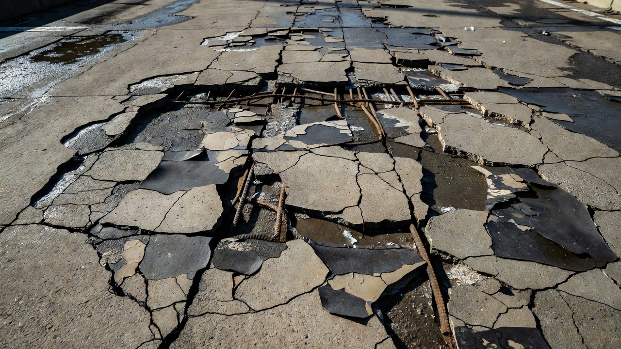
Corrosion propagation and concrete cracking — Corrosion products (Fe(OH)₂, Fe(OH)₃, Fe₃O₄) occupy 2 to 6 times the volume of the original steel. The expansive pressure generated by corrosion product accumulation produces tensile stresses in the concrete that exceed its tensile strength (typically 3-5 MPa or 435-725 psi). This initiates concrete cracking parallel to the reinforcement, visible on the deck surface as longitudinal cracks in the wheel paths.
Delamination and spalling — Cracks propagate horizontally through the concrete cover, creating delamination — fracture planes parallel to the deck surface at the level of the top reinforcing steel. Delaminated concrete sounds hollow when tapped with a hammer or chain drag. As delamination progresses, the concrete cover becomes detached and eventually spalls (falls away), exposing the reinforcing steel directly to the environment. The NACE International IMPACT study estimates the annual direct cost of corrosion in US highway bridges at $13.6 billion.
Loss of structural capacity — Section loss of reinforcing steel from corrosion reduces the load-carrying capacity of the bridge deck. Loss of concrete cover reduces the composite section and the bond between steel and concrete. In severe cases, the deck may require posting (load restriction) or replacement. Sika’s bridge deck documentation summarizes that failure to adequately waterproof leads to “accelerated corrosion of reinforcement, reduced structural integrity, increased maintenance costs, and potentially hazardous conditions for bridge users” and “a shortened service life and increased risk of failure.”
Economic consequences — The economic impact extends beyond direct repair costs. Lane closures during repairs cause user delay costs, economic disruption to businesses dependent on the bridge route, and increased vehicle operating costs from detours. The life-cycle cost benefit of effective waterproofing is substantial — the cost of membrane installation (typically 1-3% of bridge construction cost) provides 15-25 years of additional service life, while deck replacement costs 2-3 times the cost of rehabilitation with membrane replacement.
Inspection of waterproofing membrane integrity occurs at two stages: before overlay placement (immediate inspection of the exposed membrane) and during service (detecting membrane failure indirectly through deck condition assessment).
Before the asphalt wearing course is placed, the exposed membrane must be inspected for defects including blisters, punctures, tears, bare spots, edge lifting, inadequate overlap at sheet joints, and pinholes in liquid-applied systems. Inspection methods include: Visual inspection of the entire membrane surface under good lighting conditions; Wet film thickness measurement during liquid membrane application using wet film comb gauges; Dry film thickness measurement on cured membrane using magnetic film thickness gauges (for metal substrates) or ultrasonic thickness gauges (for concrete substrates); Adhesion testing using pull-off test equipment per ASTM C1583 with bond strength recorded and compared to specification minimums; Moisture testing to confirm the substrate was adequately dry at the time of application and that the membrane is fully cured; and Infrared thermography to detect voids or disbonded areas by scanning for surface temperature anomalies during the diurnal heating cycle.
After the wearing course is placed, direct inspection of the membrane is not possible without destructive removal. In-service inspection relies on indirect detection of membrane failure through observation of deck condition indicators. Detection methods include: Visual inspection of the deck surface for longitudinal cracking over the reinforcing steel in wheel paths (indicating corrosion from water ingress through failed membrane), spalling, potholes, and surface deterioration; Chain drag and hammer sounding — a chain dragged across the deck or a hammer tapped on the surface produces a hollow sound over delaminated areas (where corrosion has progressed due to water ingress through failed membrane); Infrared thermography — scanning the deck surface from a vehicle-mounted platform or drone during diurnal temperature cycles detects delamination zones by their different thermal response compared to sound concrete. IRT has been extensively validated as a method for bridge deck delamination detection and is specified in ASTM D4788-03 (Standard Test Method for Detecting Delaminations in Bridge Decks Using IR Thermography); Ground Penetrating Radar (GPR) — GPR signals reflect from interfaces with different dielectric properties including the membrane-deck interface, the top of reinforcing steel, and zones of moisture accumulation. GPR can detect chloride contamination, moisture accumulation at the membrane-deck interface, and concrete deterioration; Impact echo — a mechanical impact generates stress waves that propagate through the deck and reflect from internal interfaces, including disbonded membrane areas and delamination planes; Core sampling — extraction of cores through the overlay and membrane provides direct physical evidence of membrane condition, bond integrity, and chloride contamination at the reinforcement level. Core sampling is definitive but destructive and requires repair of the cored locations.
Visual inspection of the deck soffit (underside) provides important indirect evidence of membrane failure. Indicators include: rust staining (yellow-orange-brown discoloration) from corroding reinforcing steel; efflorescence (white crystalline deposits) from water leaching calcium hydroxide from the concrete; cracking patterns directly corresponding to the top reinforcing steel locations; and visible corrosion of exposed steel. The underside of the deck is the most accessible location for inspection on elevated bridges, and soffit conditions are routinely recorded during biennial NBIS (National Bridge Inspection Standards) inspections.
Waterproofing membrane systems are a central element of bridge deck preservation strategies. The AASHTO Bridge Preservation Guide defines preservation as “actions or treatments that preserve, rehabilitate, or replace bridge elements to extend the service life of the bridge.” Effective waterproofing is a preventive maintenance action that preserves the deck by preventing the initiation of corrosion damage.
Preventive preservation — Applying a new waterproofing membrane before significant chloride contamination has occurred prevents corrosion initiation entirely, preserving the deck in its original condition. This is the most cost-effective preservation strategy. Deck condition surveys use chloride content profiling (ASTM C1152 — acid-soluble chloride testing of powdered concrete samples at incremental depths) to determine if chloride concentration at the reinforcement level has exceeded the corrosion threshold. If chlorides are below threshold, a new membrane provides full protection.
Corrective preservation — When chloride contamination has initiated corrosion but the deck is structurally sound, preservation involves removing contaminated concrete, cleaning and treating reinforcement (by sandblasting and applying corrosion-inhibiting coatings), replacing the concrete, and installing a new waterproofing membrane. Concrete removal must extend beyond the visibly delaminated areas to remove chloride-contaminated concrete where corrosion has not yet manifested as cracking. TII DN-STR-03009 requires that concrete repair materials be compatible with the waterproofing system and have similar strength, coefficient of thermal expansion, and elastic modulus as the deck concrete. Repairs less than 5 mm thick should be avoided because they are more likely to debond.
Deck replacement preservation — When the deck is beyond repair (typically when corrosion has caused significant section loss in reinforcement or widespread spalling/deck perforation), complete deck replacement is required. The new deck is designed with a waterproofing membrane system as an integral element of the deck construction. The 2022 Bipartisan Infrastructure Law in the United States and equivalent programs in other nations emphasize deck preservation through waterproofing as a cost-effective strategy to extend the life of the aging bridge inventory.
Airport bridges that carry aircraft, vehicles, and pedestrians present unique waterproofing requirements that go beyond standard highway bridge applications. These structures include taxiway bridges (carrying aircraft between runways and aprons), runway bridges (where runways cross roads, railways, or waterways), apron bridges (at terminal areas), and service vehicle bridges. The FAA Advisory Circular AC 150/5320-6G (Airport Pavement Design and Evaluation) and ICAO Aerodrome Design Manual provide the regulatory framework for airport pavement and bridge design.
Load requirements — Airport bridge decks must support aircraft loads far exceeding highway truck loads. A Boeing 747-400 main gear load is 348,000 lbs (158,000 kg) distributed over 16 wheels, with tire pressures of 210 psi (1.45 MPa). The Airbus A380 main gear load reaches 397,000 lbs (180,000 kg) with 20 wheels. The waterproofing membrane must withstand these concentrated loads without puncture, deformation, or debonding. MMA-based systems with high compressive strength and puncture resistance are commonly specified for airport bridge decks.
Chemical resistance — Airport bridge decks are exposed to jet fuel (Jet A, Jet A-1), aviation gasoline (AvGas), hydraulic fluids (Skydrol phosphate ester-based fluids), de-icing fluids (ethylene glycol, propylene glycol, potassium acetate), and runway de-icers (urea, sodium acetate, potassium formate). These chemicals can dissolve, swell, or degrade many standard waterproofing materials. MMA and PUMA-based systems demonstrate superior chemical resistance because the cross-linked polymer matrix is highly resistant to hydrocarbon and chemical attack. Transpo Industries manufactures waterproofing membranes meeting FAA and ICAO requirements specifically formulated to resist fuel and chemical degradation on airport surfaces.
Temperature extremes — Airport bridge decks in aircraft operating areas must withstand severe thermal gradients. Jet blast from aircraft engines at takeoff thrust generates temperatures of 600-900°C at the engine exhaust nozzle and 150-300°C at the pavement surface directly behind the aircraft. The waterproofing membrane must be protected by the overlay thickness — FAA AC 150/5320-6G specifies minimum overlay thicknesses that also serve to protect the waterproofing system from jet blast effects.
Friction requirements — The wearing course over the waterproofing membrane on airport bridges must meet ICAO Annex 14 friction requirements (minimum average macrotexture depth of 1.0 mm and Design Objective Level friction values ranging from 0.72 to 0.82 depending on test equipment). The waterproofing membrane must bond sufficiently to the wearing course to ensure that the overlay maintains its friction characteristics under aircraft traffic.
FAA and ICAO compliance — The MidAmerica Airport taxiway bridge project (419 by 171 feet) demonstrates the dual compliance requirements — the waterproofing system had to meet both structural bridge standards and FAA requirements for taxiway pavements. The project documentation specifies that all materials “met both customary structural standards and FAA requirements for taxiway bridge” applications. Waterproofing membrane systems for airport bridges typically require BBA HAPAS certification (UK) or FAA acceptance through project-specific approval processes.
Waterproofing membrane replacement is a central operation in bridge deck rehabilitation projects. The replacement process when the existing deck is structurally salvageable follows a sequence defined by national standards and best practices.
Stage 1 — Removal of existing overlay and membrane: The existing asphalt wearing course is removed by milling (cold planing) or by full-depth removal using hydraulic breakers or saw-cutting. The exposed old membrane is inspected to assess its condition and determine the extent of deck contamination. If the membrane is extensively deteriorated (blistered, debonded over more than 20% of area, or multiple punctures), complete removal is required. Membrane removal is accomplished by shot blasting, scarifying, diamond grinding, or chemical stripping. Incomplete membrane removal leaves contamination that can prevent adequate bonding of the new system.
Stage 2 — Deck assessment and repair: The exposed concrete deck is inspected for: chloride contamination by profile sampling per ASTM C1152; delamination by chain drag or hammer sounding; cracking by crack mapping; spalling by visual inspection and sounding; and corrosion activity by half-cell potential mapping per ASTM C876. Delaminated and chloride-contaminated concrete is removed by hydro-demolition, chipping hammers, or scarifiers. The reinforcing steel is cleaned by sandblasting to near-white metal (SSPC-SP10) if corrosion is present. Concrete repair materials are placed per TII requirements — compatible with the waterproofing system and with similar mechanical properties as the parent concrete.
Stage 3 — Surface preparation: The prepared deck surface is grit blasted to Class U4 finish per TII DN-STR-03009. All dust, debris, and laitance are removed. The surface profile should achieve a CSP 3-5 (Concrete Surface Profile per ICRI Guideline 310.2) for optimum membrane adhesion. Moisture content is verified using moisture meters (acceptable reading depends on membrane manufacturer but is typically below 4-5% surface moisture). Concrete curing compounds, releasing agents, and other contaminants that could interfere with adhesion must be completely removed.
Stage 4 — Primer application: An epoxy or bituminous primer is applied to the prepared concrete surface in accordance with the membrane manufacturer’s specifications. The primer penetrates the concrete pores, seals the surface, and provides a chemically compatible bonding surface for the membrane. Sika’s bridge deck systems specify G-type epoxy primers that provide over 20% CO₂ reduction through bio-polymer technology and improved blush resistance for extended application windows.
Stage 5 — Membrane installation: The new waterproofing membrane is installed by spray application (liquid systems) or roll placement (sheet systems). For liquid-applied systems, multiple layers are spray-applied to achieve the specified dry film thickness. Each layer must cure before the next is applied. Wet film thickness is measured during application, and dry film thickness is verified after curing. For sheet systems, rolls are placed with side and end overlaps (typically 100-150 mm), sealed by torching or adhesive, and rolled to ensure full contact. Joints at expansion joints, drainage inlets, parapet upstands, and other details are reinforced with additional membrane strips or sealants.
Stage 6 — Protection and overlay: A protective layer (APL per TII specifications) is placed over the cured membrane where required to protect it during overlay placement. The tack coat is applied, and the asphalt wearing course is placed by mechanical paver to the specified thickness and compacted to the required density. The wearing course must be placed at a temperature that does not damage the membrane — typically 140-180°C depending on the membrane’s heat resistance specification.
The Polyguard approach to deck rehabilitation emphasizes that their waterproofing products “will prevent chlorides and moisture from infiltrating a bridge deck to prevent deterioration and corrosion” and that applying their systems during rehabilitation “significantly extends the life of the bridge” while reducing the need for frequent and costly repairs. The permeability rating of 0.05 perms for Polyguard’s 665 membrane minimizes water vapor transmission. This systematic approach to membrane replacement during deck rehabilitation, when executed with proper quality control, restores the deck’s corrosion protection for an additional 15-25 years of service life.
Bridge deck — The structural concrete or steel slab that directly supports traffic loads and is protected by the waterproofing membrane from water and chloride ingress.
Concrete deck corrosion — The electrochemical deterioration of reinforcing steel in concrete bridge decks, initiated when chloride ions from de-icing salts penetrate through failed waterproofing to the reinforcement.
Corrosion protection — Systems and materials (including waterproofing membranes, sealers, corrosion inhibitors, and cathodic protection) that prevent or slow corrosion of reinforcing steel in bridge decks.
Chloride attack — The penetration of chloride ions through concrete cover to the reinforcing steel, disrupting the passive oxide layer and initiating corrosion.
Expansion joint — A bridge component accommodating thermal and structural movement; waterproofing at expansion joints requires careful detailing to prevent water percolation beneath the membrane.
Silane sealer — A penetrating hydrophobic sealer applied to concrete bridge decks as an alternative or supplement to waterproofing membranes, typically providing 3-10 years of protection.
Wearing course — The uppermost pavement layer above the waterproofing membrane, providing the traffic-bearing surface.
Asphalt overlay — The hot-mix asphalt layer placed over the waterproofing membrane to distribute traffic loads and protect the membrane from traffic and UV exposure.
Delamination — Horizontal fracture planes in concrete bridge deck resulting from corrosion of reinforcing steel below, often caused by water ingress through failed waterproofing membrane.
Spalling — Detachment of concrete fragments from the bridge deck surface, the final stage of corrosion-induced deterioration initiated by waterproofing membrane failure.
Waterproofing membrane failure is a leading cause of bridge deck deterioration. Our advanced inspection technology detects membrane delamination, blistering, and debonding before corrosion damage develops — supporting proactive preservation and rehabilitation planning for bridge infrastructure.
The bridge deck is the uppermost structural element of a bridge, directly supporting traffic loads and providing the riding surface. Deck condition — cracking, ...
Corrosion protection for reinforced concrete encompasses multiple strategies: adequate concrete cover, low-permeability concrete with supplementary cementitious...
Chloride attack is the penetration of chloride ions from deicing salts, marine environments, or contaminated materials into concrete, destroying the passive oxi...