Whitetopping — Concrete Overlay on Asphalt Pavement
Whitetopping is a concrete overlay placed on existing asphalt pavement to provide a durable, high-strength surface. Conventional whitetopping (>100 mm) and ultra-thin whitetopping (50-100 mm, bonded) are used for rehabilitating asphalt pavements, including airfields. Covers whitetopping types, bonding, joint design, and inspection for reflective cracking and debonding.
Whitetopping — Concrete Overlay on Asphalt Pavement
Definition and Types
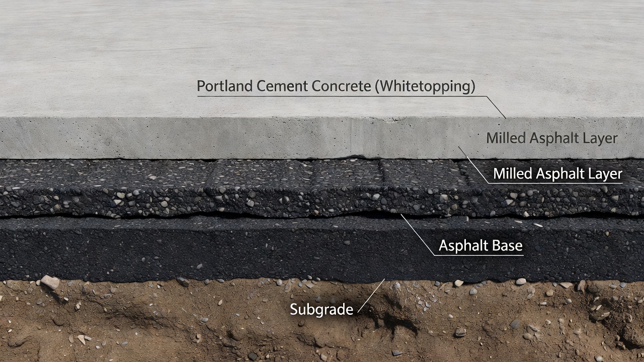
Whitetopping is a pavement rehabilitation technique in which a Portland cement concrete (PCC) overlay is placed on an existing hot-mix asphalt (HMA) pavement to provide a durable, high-strength riding surface. The term derives from the visual contrast between the white color of the concrete covering the black asphalt surface. The first documented whitetopping application in the United States dates to 1918 on South 7th Street in Terre Haute, Indiana, where a concrete overlay was placed directly over an existing asphalt pavement to address rutting and surface deterioration. Since the mid-1970s, whitetopping has been routinely used across North America, and its popularity increased dramatically in the early 1990s with the development of bonded thin and ultra-thin variants that utilize composite action between the concrete and asphalt layers.
Whitetopping is classified into three principal categories based on overlay thickness and bonding condition, as defined by the American Concrete Pavement Association (ACPA), the National Cooperative Highway Research Program (NCHRP Synthesis 338), and the Federal Highway Administration (FHWA). The classification directly influences joint spacing requirements, design methodology, construction procedures, and expected performance characteristics.
Conventional Whitetopping (also called classical or unbonded whitetopping) uses a concrete thickness of 200 mm (8 in.) or greater. ACPA defines a minimum of 150 mm (6 in.), while NCHRP 338 specifies 200 mm or more as the conventional threshold. The bond between concrete and asphalt is not purposely sought in conventional whitetopping — the existing asphalt pavement functions simply as a base layer beneath the new rigid pavement. Joint spacing follows standard rigid pavement practice at 15 to 20 feet (4.5 to 6 m), and load transfer may incorporate dowel bars. The design approach treats the overlay as new rigid pavement constructed on a flexible base, with full-depth rigid pavement design procedures applied. This variant has been in use since 1918 and became widespread between the 1950s and 1970s. Caltrans placed 175–225 mm plain concrete overlays on asphalt during this period, and these sections provided excellent service for well over 20 years, demonstrating the long-term viability of the conventional approach.
Thin Whitetopping (TWT) is a bonded concrete overlay with a thickness of 100 to 150 mm (4 to 6 in.). The FHWA TechBrief (FHWA-HIF-07-025) places TWT at 100–150 mm, while the Colorado Department of Transportation (CDOT), which pioneered TWT beginning in 1990, specifies 4 to 6 in. of concrete. The Colorado experience established the standard for thin whitetopping design and construction in the United States. Bonding is purposely created in TWT through milling of the existing asphalt surface, thorough cleaning, and careful concrete placement. The bond creates composite action between the concrete and asphalt, significantly reducing tensile stresses in the overlay. Joint spacing is typically 1.8 m (6 ft) square panels. TWT is designed for highways, intersections, primary roads, general aviation airports, and other medium-to-high traffic applications. CDOT assumes a 20-year design life for TWT with one 10 mm grinding operation performed at mid-life to restore surface friction and smoothness.
Ultra-Thin Whitetopping (UTW) is the thinnest variant, with a concrete overlay thickness of 50 to 100 mm (2 to 4 in.) per the ACPA definition. Some sources (FHWA) extend the lower range down to 2 in. (50 mm). Bonding is essential and must be reliable, as the composite section is the primary structural mechanism that reduces load-induced tensile stresses to acceptable levels. Joint spacing is extremely tight at 0.6 to 1.5 m (2 to 5 ft), with a recommended maximum of 12 to 15 times the slab thickness. UTW was first used in 1991 on a landfill access road in Louisville, Kentucky, and rapidly gained acceptance across the United States. By 2001, ACPA had documented over 200 UTW projects in 35 states totaling 765,000 m² (916,000 yd²). Typical applications include low-volume roads, intersections, bus stops, parking lots, and airport aprons and taxiways. The original Louisville experiment carried 400–600 trucks per day, representing 20 to 100 times the traffic of typical low-volume roads where UTW was originally envisioned.
A fourth variant, Thin Composite Whitetopping, occupies an intermediate thickness range between UTW and conventional whitetopping and was developed specifically for higher-volume roadways and Interstate highway applications. Three experimental projects were built in 1997 to validate this approach for higher traffic levels.
Parameter
UTW
TWT (CDOT)
TWT (TxDOT)
Conventional
Thickness
50–100 mm (2–4 in.)
100–150 mm (4–6 in.)
100–178 mm (4–7 in.)
≥ 150–200 mm (6–8 in.)
Bond required
Essential
Purposely sought
Purposely sought
Not required
Joint spacing
0.6–1.5 m (2–5 ft)
1.8 m (6 ft) square
1.8 m (6 ft) square
4.5–6 m (15–20 ft)
Max joint spacing
12–15× thickness
—
6 ft
Per FAA/AASHTO
Min HMA remaining
75 mm (3 in.)
75 mm (3 in.)
100 mm (4 in.)
Variable
Milling depth
13–50 mm (0.5–2 in.)
13–50 mm (0.5–2 in.)
Remove rutting ≥ 0.5 in.
Optional
Concrete strength (28-day)
> 20 MPa (3,000 psi) fast-track
29 MPa (4,200 psi)
Per specification
Standard
Flexural strength (28-day)
—
4.5 MPa (650 psi) lab trial
Per specification
Standard
Air content
—
4–8%
Per specification
Standard
Max w/cm ratio
—
0.44
Per specification
Standard
Dowel bars
No
No
No (< 7 in.); Yes (≥ 7 in.)
Yes
Tie bars (longitudinal)
Optional
Yes @ 900 mm (36 in.)
Yes
Yes
Joint sealing
Typically not sealed
Yes (silicone)
Per agency practice
Yes
Design life
Variable by traffic
20 years
5–10 years
20–30+ years
Saw-cut depth
1/4–1/3 of thickness
1/4–1/3 of thickness
Per specification
Standard
Bonding in Whitetopping
The defining technological innovation behind bonded whitetopping — both UTW and TWT — is the creation of composite action between the concrete overlay and the underlying asphalt pavement. When the concrete overlay bonds monolithically to the asphalt, the neutral axis of the combined section shifts downward relative to the concrete layer alone. This shift dramatically reduces the tensile stresses at the bottom of the concrete layer under traffic loading, which is the fundamental mechanism that allows thin concrete sections to carry traffic loads without structural failure.
Quantitative stress reduction data from ACPA illustrates the magnitude of this effect with precision. For a 75 mm thick concrete overlay on 100 mm of asphalt under a 36 kN wheel load, the maximum tensile stress along a free edge measures 8.49 MPa in an unbonded condition but only 2.90 MPa when fully bonded — a reduction of approximately 66%. Near a slab corner, the unbonded tensile stress of 6.12 MPa drops to 3.68 MPa in the bonded condition. FHWA and CDOT investigations confirm that reliable bonding reduces critical tensile stresses by a minimum of 25% in practical configurations, with larger reductions achieved for thinner overlays and stiffer asphalt layers. This stress reduction is the reason UTW sections only 50–100 mm thick can successfully carry truck and aircraft loads that would cause rapid failure in an unbonded section of the same thickness.
Surface preparation is the single most critical factor for achieving and maintaining reliable bonding over the design life of the overlay. The existing HMA surface is milled to a typical depth of 13 to 50 mm (0.5 to 2 in.). Milling serves three essential purposes: removing surface distresses such as rutting, shoving, and oxidation; exposing fresh aggregate to provide mechanical interlock between the fresh concrete and the existing asphalt; and creating a uniform profile with a roughened texture that maximizes bond area. A minimum of 75 mm (3 in.) of asphalt must remain in place after milling to provide adequate structural support for the overlay system. TxDOT requires 100 mm (4 in.) minimum remaining asphalt thickness.
After milling, the surface must be swept multiple times and then air-blasted or power-blasted to remove all dust, debris, and loose particles. Bond failure in whitetopping is frequently traced to inadequate cleaning during forensic investigations. The milled surface should be wetted immediately before concrete placement to prevent rapid water absorption from the fresh concrete mix, which would reduce the water available for hydration at the interface. However, standing water must not be present when concrete is placed, as a water film at the interface prevents bond formation.
Traffic control during the surface preparation and paving window is critical. Once cleaned, the prepared surface must remain clean until concrete is placed. If traffic runs over the milled surface before paving, it must be recleaned. Water blasting or abrasive blasting can substitute for milling when milling equipment is not available or when the asphalt layer is too thin to allow milling.
CDOT has established through field experience that concrete does not bond well to new (fresh) asphalt pavement, whether milled or not. Therefore, thin whitetopping is not recommended on newly constructed HMA surfaces. The bond quality depends on four factors working together: the strength and integrity of the existing concrete mix, surface cleanliness achieved through proper milling and cleaning, consolidation of the overlay during placement to ensure intimate contact at the interface, and proper jointing and curing techniques that prevent early-age cracking at the bond line.
Joint Design and Spacing
Joint spacing is the most critical design parameter for whitetopping performance, particularly for UTW and TWT where the overlay thickness is small relative to conventional rigid pavements. The fundamental principle is that short joint spacing reduces the moment arm through which applied wheel loads induce bending stresses in the concrete slab. This reduction in bending moment is the mechanism that allows thin concrete slabs to carry heavy loads without exceeding the flexural strength of the concrete.
Short joint spacing also minimizes curling and warping stresses caused by temperature and moisture gradients across the thin slab. In a 75 mm thick UTW section, a temperature differential of 10°C between the top and bottom of the slab induces significantly less curling stress in a 0.6 m panel than in a 1.8 m panel of the same thickness. In UTW sections specifically, the short spacing causes loads to transfer primarily through deflection of the slab system rather than through bending of individual slabs. This deflection-based load transfer mechanism is the fundamental engineering principle that allows very thin concrete slabs to function without structural failure under traffic loads.
UTW joint spacing ranges from 0.6 to 1.5 m (2 to 5 ft), with the recommended maximum expressed as 12 to 15 times the slab thickness. For a 75 mm (3 in.) UTW section, this translates to a maximum joint spacing of 0.9 to 1.125 m (36 to 44 in.). The original Louisville UTW experiment used two joint spacing configurations — 0.61 m (2 ft) and 1.83 m (6 ft) — and results showed a dramatic performance difference. Panels with 0.61 m spacing exhibited significantly less corner cracking than the 1.83 m panels, confirming the importance of tight joint spacing for UTW.
Thin whitetopping under CDOT standard practice uses 1.8 m (6 ft) square panels for all applications. This spacing has been validated through over 20 years of Colorado experience on Interstate highways carrying up to 52,000 ADT. Longitudinal joints in CDOT TWT are tied with deformed tie bars spaced at 900 mm (36 in.) to maintain aggregate interlock and prevent joint opening. TxDOT also specifies 6 ft square panels and requires that all panels be square except in transition areas where geometric constraints prevent square layout. Conventional whitetopping uses standard rigid pavement joint spacing of 15 to 20 ft (4.5 to 6 m).
Saw-cut depth for all whitetopping types is 1/4 to 1/3 of the overlay thickness. For a 100 mm TWT section, this means saw cuts penetrate 25 to 33 mm into the concrete. Sawing should be performed as early as possible after concrete placement to control random cracking. Lightweight early-entry saws are commonly used for UTW, allowing sawing within 2 to 4 hours of concrete placement before the concrete develops its full strength. Joints should be kept out of wheel paths whenever possible, as this significantly reduces load-related reflective cracking and corner break distress. When longitudinal joints fall within wheel paths, the combination of edge loading and traffic repetition accelerates corner cracking.
Joint sealing practice varies significantly by whitetopping type and agency. UTW joints are typically not sealed, because the extremely short joint spacing minimizes individual joint movement to fractions of a millimeter, and no performance benefit from sealing has been demonstrated in field research. CDOT seals all TWT joints with silicone sealant applied in a single saw cut configuration. TxDOT follows conventional joint sealing practice for its TWT sections. Dowel bars are not used across transverse joints in TWT per CDOT standard practice, but MnROAD research demonstrated that 1-inch diameter dowel bars in Cell 92 eliminated faulting while the undoweled Cell 97 showed significant faulting after similar traffic exposure. TxDOT specifies dowel bars for overlays 7 in. or thicker.
Joint Design Parameter
UTW
TWT
Conventional
Joint spacing
0.6–1.5 m (2–5 ft)
1.8 m (6 ft)
4.5–6 m (15–20 ft)
Max spacing formula
12–15 × thickness
Fixed at 6 ft
Per AASHTO/FAA
Saw-cut depth
1/4–1/3 thickness
1/4–1/3 thickness
1/4–1/3 thickness
Joint sealing
Not sealed
Silicone sealant
Sealed per spec
Dowel bars
None
None (CDOT); Optional (TxDOT)
Typically required
Tie bars at longitudinal joints
Optional
Yes, at 900 mm (36 in.)
Yes
Saw timing
Within 2–4 hours
As early as possible
Next day
Whitetopping Construction
Whitetopping construction follows a systematic sequence that begins with surface preparation and proceeds through concrete placement, finishing, curing, and joint sawing. The construction process distinguishes bonded whitetopping from conventional unbonded overlays primarily in the intensity of surface preparation and the urgency of sawing operations.
Surface preparation begins with milling the existing HMA surface to a depth of 13 to 50 mm (0.5 to 2 in.), with the critical constraint that a minimum of 75 mm (3 in.) of asphalt remains after milling to maintain structural support for the overlay. For TxDOT projects, the minimum remaining asphalt thickness is 100 mm (4 in.). The milling operation uses conventional asphalt milling machines with a drum equipped with carbide cutting teeth. The milled surface should have a uniform texture with approximately 2 mm amplitude between peaks and valleys to maximize mechanical interlock.
After milling, the surface is cleaned through a sequence of operations: initial sweeping with a mechanical broom to remove large debris, followed by a power broom or vacuum sweeper for fine material, and finally air-blasting with compressed air to remove all remaining dust from the surface texture. Some specifications require water blasting after milling to ensure complete removal of asphalt fines. The surface must be moistened immediately before concrete placement to prevent rapid water absorption from the fresh concrete, but standing water must not be present. Surface preparation should be limited to the area that can be paved within a single shift to prevent recontamination.
Concrete placement uses conventional equipment appropriate to the project scale. Slipform pavers are used for large-scale highway and airfield projects where continuous paving production is required. Fixed-form pavers or vibrating screeds are used for smaller or constrained areas such as intersections, bus stops, and parking lots. Whitetopping is always placed in a single pass — concrete overlays are never constructed in multiple lifts, as a cold joint between lifts would create a plane of weakness and potential delamination. For intersection closures, fast-track mix designs are commonly used to achieve 2,500 psi (17 MPa) compressive strength within 24 hours, enabling weekend closures from Friday evening to Tuesday morning. The SH 83 project in Colorado placed 90,100 m² of TWT in 65 working days using fast-track concrete.
Concrete materials follow standard rigid pavement specifications with modifications specific to thin overlays. CDOT Class P concrete for TWT requires a minimum 28-day compressive strength of 29 MPa (4,200 psi), air content of 4% to 8%, and a maximum water-cementitious materials ratio of 0.44. Lab trial batches must demonstrate a 28-day flexural strength of 4.5 MPa (650 psi). Synthetic fibers — typically polypropylene or polyolefin microfibers — are commonly used in UTW and TWT mixes at dosages of 0.1% to 0.3% by volume to improve post-crack integrity and control plastic shrinkage cracking. CDOT specifically does not recommend steel fibers where de-icing salts may be used, as corrosion of exposed fibers can cause surface staining and spalling. High-early-strength concrete mixtures for fast-track projects typically achieve over 20 MPa (3,000 psi) compressive strength within 24 hours through the use of Type III (high early strength) cement, reduced water-cement ratio, and chemical accelerators.
Finishing and texturing follow conventional concrete pavement procedures. The surface is struck off to grade by the paver, then finished using a longitudinal float to close surface voids. Texture is applied using burlap drag, artificial turf drag, or a metal tine rake to provide macrotexture for surface friction and drainage. For airport applications, transverse tining or grooving is commonly specified to meet FAA friction requirements.
Curing is a critical step for thin whitetopping because thin slabs have a high surface-area-to-volume ratio and lose water rapidly through evaporation, especially in hot or windy conditions. Curing compound should be applied at twice the normal rate (approximately 0.2 L/m² instead of 0.1 L/m²) compared to conventional concrete pavements. White-pigmented curing compound is preferred in sunny conditions to reflect solar radiation and reduce slab temperature. A critical caution: curing compound must not be sprayed onto the prepared asphalt surface ahead of the paving operation, as this will completely prevent bonding and cause debonding failure.
Joint sawing should commence as early as possible to control random cracking. For UTW, lightweight early-entry saws powered by gasoline engines allow cutting within 2 to 4 hours of concrete placement, before the concrete develops its full compressive strength. The saw-cut depth is 1/4 to 1/3 of the overlay thickness — for a 75 mm UTW section, the cut depth is 19 to 25 mm. Transverse joints are sawed first in a sequence that follows the paving operation, typically at intervals matching the specified joint spacing. Longitudinal joints are sawed using gang-mounted saws on guide bars. For multi-lane paving projects, transverse joints in the new lane must be matched with the cracked joint pattern in the adjacent existing lane to prevent reflective cracking from misaligned joints.
Opening to traffic depends on concrete strength gain and joint sawing completion. Fast-track concrete mixes can open to traffic within 24 hours of placement. Standard (non-fast-track) mixes typically require 3 to 7 days of curing before traffic loading. For airport applications, FAA AC 150/5320-6G requires that concrete achieve minimum flexural strength before aircraft loading.
Performance Characteristics
Whitetopping delivers distinct performance advantages over both HMA overlays and new rigid pavements, particularly in rutting resistance, structural durability, and life-cycle cost efficiency. Understanding these characteristics enables engineers to select the appropriate whitetopping type for specific project conditions.
Rutting resistance is the primary motivation for many whitetopping projects, particularly at intersections, bus stops, and heavy truck climbing lanes where asphalt rutting is recurrent and costly to manage. UTW and TWT eliminate rutting by providing a rigid concrete layer that distributes wheel loads over a wider area and does not deform plastically under repeated loading. The technique was originally developed specifically for locations where recurrent rutting was a persistent maintenance problem. At the FHWA Accelerated Loading Facility (ALF), controlled comparisons of HMA rutting to UTW cracking demonstrated that a concrete overlay provides a permanent structural solution to asphalt rutting. After 1 million load applications, the HMA section showed 12.7 mm of rutting while the UTW section showed zero measurable rutting.
Durability data from multiple state agencies confirms that whitetopping provides long service life with minimal structural deterioration. CDOT assumes a 20-year service life for TWT in its life-cycle cost analysis, with one grinding at 10 mm depth performed at mid-life to restore surface friction. CDOT’s SH 83 project carried 52,000 ADT with 3.4% trucks over a 20-year period with only routine maintenance. Caltrans placed 175–225 mm plain concrete overlays on asphalt in the 1960s and 1970s that provided excellent service for well over 20 years with no major structural rehabilitation. The Iowa DOT has whitetopped over 650 km of county roadways since 1977, with many sections still in service after 40+ years. The original Louisville UTW project carried 400–600 trucks per day and demonstrated that even the thinnest overlays can perform well with proper design and construction, though UTW design life is more variable than TWT.
Life-cycle cost comparisons consistently favor whitetopping when user-delay costs from construction are included. CDOT’s 2005 life-cycle cost analysis compared TWT (100–150 mm concrete) against periodic 50 mm asphalt overlay every 10 years over a 20-year analysis period. TWT agency costs were only 1% higher than the asphalt overlay alternative, but when user-delay costs from the two asphalt overlay construction events were included, TWT was 11% less expensive overall. TxDOT reports that TWT provides better serviceability, longer service life, lower life-cycle cost, and improved safety compared to asphalt overlay alternatives for its applications. The analysis period and discount rate used in LCCA significantly influence results, but the trend consistently favors whitetopping when user delays are valued.
Load transfer in UTW and TWT relies primarily on aggregate interlock at joints, which is effective because short joint spacing reduces the load demand on any individual joint. When a wheel load is applied near a joint, the aggregate interlock across the joint transfers 40% to 60% of the load to the adjacent slab. Load transfer efficiency (LTE) is measured using Falling Weight Deflectometer (FWD) testing, with values above 70% considered good and values below 50% indicating loss of interlock. MnROAD research demonstrated that 1-inch diameter dowel bars in Cell 92 eliminated faulting entirely in TWT sections carrying over 1 million ESALs per year on I-94, while the undoweled Cell 97 exhibited measurable faulting after similar traffic. CDOT does not require dowel bars for TWT, but TxDOT specifies dowels for overlays 7 in. or thicker.
Traffic capacity of whitetopping spans a wide range depending on overlay thickness and design parameters. CDOT projects have carried up to 52,000 ADT (SH 83) with 3.4% trucks over a 20-year design life. SH 121 (Wadsworth Blvd) was designed for 30,000 ADT with projected growth to 40,000 by 2020. MnROAD I-94 carries over 1 million ESALs per year with 25,000 ADT and more than 12% trucks. TxDOT’s design table covers 200 to 1,000 trucks per day per lane. UTW is typically designed for lower traffic volumes but the original Louisville project demonstrated successful performance under 400–600 trucks per day.
Whitetopping Distresses
Understanding whitetopping distress mechanisms is essential for condition assessment, inspection, and rehabilitation planning. The distress types observed in whitetopping differ from those in conventional rigid pavements due to the thin section, bonded interface, and interaction with the underlying asphalt layer. Each distress type has distinct causes, progression patterns, and implications for pavement performance.
Corner cracking is the most common distress in UTW and thin whitetopping, consistently documented across ALF studies, MnROAD test sections, and FDOT airport evaluations. Corner cracks initiate at the slab corner and propagate at approximately 45 degrees across the corner. The mechanism involves load-induced tensile stresses at slab corners combined with loss of support from the underlying asphalt layer. When a wheel load passes over a slab corner, the combination of tensile stress at the top surface and shear stress at the interface creates a complex stress state that initiates cracking. The distress is significantly mitigated by closer joint spacing — the original Louisville experiment showed that 0.61 m (2 ft) spacing produced dramatically less corner cracking than 1.83 m (6 ft) spacing. Corner cracking occurs primarily along the inside wheelpath where the longitudinal joint and wheel load coincide, making joint placement relative to wheelpaths a critical design consideration.
Reflective cracking occurs when pre-existing transverse cracks in the HMA layer propagate upward through the concrete overlay. This is a critical distress mechanism specific to whitetopping that does not occur in conventional rigid pavements on granular bases. Research by Vandenbossche and Barman (TRB 2010) established that reflective cracking is driven by two combined mechanisms. First, thermal contraction of the HMA layer during winter months creates horizontal tensile strains in the HMA, which concentrate at the tip of existing cracks and transfer stress to the bottom of the concrete overlay. Second, vehicle wheel loads passing over the crack increase the tensile stress at the crack tip in the concrete, causing the crack to propagate upward through the overlay thickness. Cracks develop during winter and early spring and develop faster in driving lanes than passing lanes, confirming the role of traffic loading.
The critical stiffness ratio DₚCC/HMA is the key design criterion for predicting reflective cracking. The ratio is defined as DₚCC/HMA = (EₚCC × hₚCC³ × (1 − μ²HMA)) / (EHMA × hHMA³ × (1 − μ²PCC)) where E is elastic modulus, h is layer thickness, and μ is Poisson’s ratio for each material. When this ratio falls below 1.0 during the coldest month of the year, reflection cracks are expected to develop. The rate of crack development depends on load-related stresses. MnROAD found that 152 mm (6 in.) overlays showed no reflective cracking after 11+ years when DₚCC/HMA remained above 1.0, while thinner overlays (76–127 mm) all exhibited reflection cracking when DₚCC/HMA fell below 1.0. Counter-intuitively, thinner HMA layers (e.g., 76 mm on US-169) produced less reflective cracking than thicker HMA layers (178 mm+ on I-94) because the lower composite stiffness reduced the thermal stress concentration at crack tips.
Debonding or delamination is the loss of bond between the concrete overlay and the asphalt substrate. This is the most structurally critical distress because it eliminates composite action and causes the concrete section to behave as an unbonded overlay, dramatically increasing tensile stresses. Causes include inadequate surface preparation (insufficient milling depth, poor texture), incomplete cleaning (dust film at interface), contamination of the milled surface (fuel spills, oil, dirt from traffic), curing compound overspray onto the prepared asphalt, and moisture intrusion at the interface through unsealed joints. Debonding begins at slab edges and corners and propagates inward under traffic loading. Forensic investigations of distressed whitetopping frequently trace structural failure to debonding caused by inadequate surface preparation.
Transverse cracking is the second most common distress in UTW and TWT. It can be load-related (fatigue cracking from repeated wheel loads at slab midspan) or reflective from underlying HMA cracks. Transverse cracks are more prevalent in thinner overlays under 100 mm (4 in.) where the section modulus is insufficient to resist fatigue stresses. Longitudinal cracking develops along longitudinal joints in thicker overlays (≥ 127 mm / 5 in.), particularly where joints lie in wheelpaths. These cracks are related to edge loading and joint deterioration. Joint faulting (vertical elevation difference across joints) occurs in undoweled sections when aggregate interlock degrades under repeated loading and fine material pumps out of the joint. Faulting is mitigated by sealed joints and dowel bars. Joint spalling results from aggregate interlock breakdown under repeated loading or freeze-thaw damage at joint edges.
Distress Type
Primary Cause
Typical Location
Mitigation
Corner cracking
Load stress + loss of support
Slab corners in wheelpath
Shorter joint spacing, keep joints out of wheelpaths
Reflective cracking
HMA crack propagation through overlay
Transverse, aligns with existing HMA cracks
Thicker overlay, lower DPCC/HMA ratio
Debonding
Poor surface preparation
Edges and corners, propagates inward
Milling, cleaning, proper curing compound use
Transverse cracking
Load fatigue or reflection
Mid-slab, perpendicular to traffic
Adequate thickness, proper joint spacing
Longitudinal cracking
Edge loading
Along longitudinal joints
Tie bars, keep joints out of wheelpaths
Joint faulting
Aggregate interlock loss
Transverse joints
Sealed joints, dowel bars in thicker sections
Joint spalling
Aggregate breakdown, freeze-thaw
Joint edges
Quality concrete, air entrainment
Inspection of Whitetopping
Whitetopping inspection requires a combination of visual condition assessment, non-destructive testing, and physical sampling to evaluate both the concrete layer condition and the bonded interface condition. The inspection methodology must be adapted from conventional rigid pavement procedures to account for the specific failure modes of bonded overlays.
Visual condition assessment uses standardized pavement condition rating systems appropriate for the facility type. The PASER (Pavement Surface Evaluation and Rating) system is commonly used for airfield rigid pavements, providing a 1-to-10 rating based on distress type, severity, and extent. ASTM D5340 is the standard test method for Airport Pavement Condition Index (PCI) surveys, which calculates a numerical index from 0 (failed) to 100 (excellent) based on distress density and severity. However, FDOT has noted that the standard ASTM D5340 PCI methodology may be unsuitable for whitetopping overlays at airports because the distress types, severity levels, and extent measurements developed for conventional rigid pavements do not accurately capture the specific failure modes of bonded overlays. FDOT developed modified procedures for whitetopping condition analysis at Florida airports, incorporating historical data review, network inventory updates, and modified distress definitions that account for whitetopping-specific issues such as debonding and reflective cracking.
Falling Weight Deflectometer (FWD) testing evaluates structural capacity and load transfer efficiency (LTE) at joints. FWD applies a controlled impulse load (typically 40 to 160 kN for airfield pavements) to the pavement surface and measures the resulting deflection basin using geophones at radial distances from the load plate. The deflection data can be used to backcalculate elastic moduli of the concrete overlay, the asphalt layer, and the subgrade. Reduced LTE values at joints indicate loss of aggregate interlock, which may signal the need for joint rehabilitation. FWD can also identify areas of possible debonding by detecting anomalous deflection responses — a debonded area shows higher deflections and a different deflection basin shape than a well-bonded area. FWD testing should be performed at 20 to 50 m intervals along each lane, with additional testing at joints and identified distress locations.
Ground Penetrating Radar (GPR) is included in FAA AC 150/5320-6G (Appendix E) as a recognized non-destructive evaluation method for airport pavements. GPR uses high-frequency electromagnetic pulses (typically 1.0 to 2.5 GHz for pavement applications) to image subsurface layers. GPR can measure layer thicknesses with accuracy of ±5 mm, detect debonding at the concrete-asphalt interface (identified by a strong reflection at the interface where air or water has displaced the bond), and identify subsurface anomalies including pre-existing cracks in the HMA layer that are at risk of reflecting through the overlay. GPR surveys can be conducted at traffic speed, making them efficient for network-level condition assessment.
Coring provides direct physical verification of overlay thickness, bond condition, and material properties. Cores are typically 100 mm (4 in.) or 150 mm (6 in.) in diameter and are extracted at representative locations including intact areas, distressed areas, and joints. Each core provides data on actual overlay thickness (which may differ from design thickness due to construction variability), concrete compressive strength (tested per ASTM C39), and HMA thickness and condition. Direct shear testing on field cores quantifies bond strength at the concrete-asphalt interface. The core is placed in a shear test fixture and loaded until the interface fails. Bond strength values can be correlated with expected overlay performance and are essential for forensic investigation of distressed sections. A bond strength below 0.5 MPa indicates poor bonding that will likely result in debonding under traffic.
Non-destructive evaluation (NDE) methodologies continue to evolve for whitetopping-specific applications. FDOT’s SAPMP (Statewide Airport Pavement Management Program) methodology combines historical data review, network inventory updates, PASER section definition, field data collection, and condition rating. For whitetopping at Florida airports, the modified procedures developed by FDOT adjust distress identification, severity rating, and density calculations to better reflect whitetopping performance. These modifications include adding debonding as a distinct distress type, adjusting reflective cracking severity based on crack width and spalling, and reducing the weight of non-critical distresses in the overall condition index calculation.
Whitetopping for Airport Pavements
Whitetopping is used on airport pavements — runways, taxiways, and aprons — where existing asphalt surfaces have deteriorated, exhibit recurrent rutting, or require strengthening to accommodate heavier aircraft. The Federal Aviation Administration (FAA) addresses whitetopping under Advisory Circular 150/5320-6G: Airport Pavement Design and Evaluation (June 2021), which is mandatory for all Airport Improvement Program (AIP) and Passenger Facility Charge (PFC) funded projects.
Under FAA AC 150/5320-6G, whitetopping is addressed in Chapter 4 (Pavement Maintenance, Rehabilitation and Reconstruction), Sections 4.7 (Overlay Structural Design) and 4.10 (Preparation of Existing Pavement Surface for Overlay). The FAARFIELD v2.0 software is used for overlay structural design, with concrete overlay on asphalt handled as a “concrete on flexible” overlay configuration within the software. FAARFIELD uses layered elastic theory and the FAA’s design curves to determine required overlay thickness based on traffic (departure cycles by aircraft type), subgrade strength (CBR or k-value), and existing pavement condition. The FAA specifies a minimum thickness of 125 mm (5 in.) for unbonded concrete overlays on existing concrete pavements, though this minimum may vary for bonded overlays depending on the specific project conditions and design traffic. Joint spacing for airport whitetopping follows FAA Table 3-7 guidance for rigid pavement contraction joints, with maximum spacing of 6.1 m (20 ft) for 250 mm slabs and proportionally shorter spacing for thinner overlays.
Florida airport case studies from the FDOT SAPMP (Statewide Airport Pavement Management Program) document three whitetopping installations that do not conform to current FAA AC standards. These case studies provide valuable real-world performance data for whitetopping on general aviation airports.
Key findings from the Florida airport evaluations include non-standard joint layout and spacing (deviating from FAA guidance), unsealed joints (which may accelerate joint deterioration through moisture infiltration), unknown concrete strength characteristics (no records of mix design or strength testing), and observed distresses including corner spalling, corner breaks, faulting, and joint spalling. The standard ASTM D5340 PCI methodology was deemed potentially unsuitable for evaluating whitetopping condition at these airports, leading FDOT to develop modified evaluation procedures specific to whitetopping that adjust distress definitions, severity ratings, and density calculations.
ICAO references for whitetopping are primarily determined through national aviation authority specifications, as ICAO delegates detailed pavement design and rehabilitation standards to member states. FAA AC 150/5320-6G now aligns with the ICAO ACR-PCR (Aircraft Classification Rating / Pavement Classification Rating) protocol for pavement strength reporting. No stand-alone ICAO document specifically addressing whitetopping has been published, but ICAO Aerodrome Design Manual Part 3 (Pavements) provides general overlay design guidance applicable to whitetopping. The ACPA and CP Tech Center have conducted webinars on concrete overlays for airfield pavement applications that reference ICAO standards.
At airports, whitetopping offers the critical advantage of chemical resistance to jet fuel spills and de-icing fluids, which chemically degrade asphalt binders and cause surface raveling, stripping, and structural weakening of HMA pavements. For apron areas where fuel spills are frequent and heavy aircraft are parked for extended periods, whitetopping is often the preferred rehabilitation solution despite the higher initial cost. The rigid concrete surface also resists the static load indentation that can occur in asphalt aprons under parked aircraft.
Whitetopping vs. Asphalt Overlay
The choice between whitetopping and an asphalt (HMA) overlay for pavement rehabilitation depends on traffic levels, existing pavement condition, budget, construction timeline, and long-term performance requirements. Each approach has distinct technical and economic characteristics that determine its suitability for specific project conditions.
Factor
Whitetopping
Asphalt Overlay (HMA)
Rutting resistance
Eliminates rutting — rigid concrete surface
Prone to rutting under heavy, slow traffic
Service life
20+ years (TWT); 30+ years (conventional)
8–15 years typical; 15–20 with high-quality PMB
Life-cycle cost (agency)
Higher initial cost by 10–30%
Lower initial cost
Life-cycle cost (with user delays)
Lower overall cost (CDOT: 11% less)
Higher overall cost with frequent construction
Construction time to open
7–14 days curing (fast-track); 28 days standard
24 hours cooling; open same day
Reflective cracking
Potential issue; mitigated by bond and joint design
Common issue; mitigated by SAMI interlayers
Chemical resistance
Excellent (fuel, de-icers, hydraulic fluids)
Poor; requires PMB or protective treatments
Surface friction
Excellent; grooving or tining provides consistent friction
Good; requires proper aggregate selection
Thermal stability
Low thermal susceptibility
High thermal susceptibility
Repair complexity
Full slab replacement for structural repairs
Milling and overlay or localized patching
Recyclability
100% recyclable as crushed aggregate
100% recyclable in new HMA
Noise
Higher tire-pavement noise without surface treatment
Lower noise characteristics
CDOT’s life-cycle cost analysis (2005) comparing TWT (100–150 mm concrete) against periodic 50 mm asphalt overlays every 10 years over a 20-year analysis period provides quantitative evidence for the economic comparison. TWT agency costs (construction, maintenance, rehabilitation) were only 1% higher than the asphalt overlay alternative. However, when user-delay costs from two asphalt overlay construction events (each requiring lane closures and traffic delays) were included, TWT was 11% less expensive overall. This analysis assumed 20 years of TWT service life with one grinding at mid-life, versus two asphalt overlays in the same period. The comparison demonstrates that whitetopping becomes economically favorable when user-delay costs are considered, which is particularly relevant for high-volume roadways and airports where construction-related delays impose substantial economic costs.
For airport pavements, the comparison shifts further in favor of whitetopping due to chemical resistance requirements. Jet fuel spills and de-icing fluid applications chemically degrade asphalt binders, causing surface raveling and structural weakening that require premature rehabilitation. Whitetopping provides a chemically inert surface that resists these attacks. Apron areas, where aircraft are parked for extended periods with static loads and fuel spills, particularly benefit from whitetopping. Airfield whitetopping is typically designed with higher concrete strength (35–45 MPa compressive strength) and lower water-cement ratio (0.40–0.42) than highway whitetopping to maximize chemical resistance and abrasion resistance.
Ultra-Thin Whitetopping Research
UTW has been the subject of extensive research since its first application in 1991. The ACPA has documented over 200 UTW projects in 35 states between 1992 and 2001, totaling 765,000 m² (916,000 yd²) of overlay area. Major research programs include the FHWA Accelerated Loading Facility (ALF), MnROAD test sections, Transportation Pooled Fund TPF 5(165), and university studies at the University of Pittsburgh and Rutgers University. This research has established the mechanistic understanding of UTW behavior and provided the foundation for current design procedures.
Transportation Pooled Fund TPF 5(165) — “Development of Design Guide for Thin and Ultra-thin Concrete Overlays of Existing Asphalt Pavements” — produced the Task 1 Report in 2011 (University of Pittsburgh, principal investigator Dr. Julie Vandenbossche). This research established the stiffness ratio criterion (DₚCC/HMA < 1.0 as predictor of reflective cracking) that is now used in mechanistic-empirical UTW design. The research also developed fatigue models for bonded whitetopping that relate traffic loading, climate effects, material properties (concrete modulus of rupture, HMA modulus), and existing HMA condition to expected performance life. The design procedure considers monthly temperature data to evaluate the stiffness ratio throughout the year, identifying months when reflective cracking risk is highest.
Rutgers University CAIT (FHWA-NJ-2001-018) developed a design guide for UTW that established quantitative relationships between overlay thickness, joint spacing, traffic loading (ESALs), and expected performance. Key findings include: joint spacing of 12–15 times slab thickness is required for UTW structural performance; bonding verification through coring at 3–6 locations per project is essential for quality assurance; synthetic fibers at 0.1–0.2% by volume improve post-crack integrity without affecting structural capacity; and the minimum practical overlay thickness is 50 mm (2 in.) with 75 mm (3 in.) recommended for traffic above 200 trucks per day.
MnROAD test cells on I-94 (Cells 92, 93, 97) and US-169 (Cell 53) provided long-term performance data under actual interstate traffic conditions over 11+ years. Cell 92 (100 mm TWT on 178 mm HMA, doweled with 1-inch dowels, sealed joints) performed excellently with no faulting and minimal cracking throughout the monitoring period. Cell 97 (100 mm TWT on 127 mm HMA, undoweled, sealed joints) showed faulting of 2–3 mm but no structural failure. US-169 Cell 53 (76 mm TWT on 76 mm HMA) demonstrated that thinner HMA layers produce less reflective cracking because the lower HMA stiffness reduces thermal stress concentration at crack tips. The MnROAD data confirmed that reflective cracking is primarily a cold-weather phenomenon driven by the stiffness ratio criterion.
The National Concrete Overlay Explorer (overlays.acpa.org), maintained by ACPA, provides the most comprehensive publicly available repository of whitetopping case histories, design guidance, and technical fundamentals. The site includes project search by location, overlay type, thickness, and performance metrics. The ACPA Guide to Concrete Overlay Solutions (TB021P) covers all six overlay types recognized by ACPA, including UTW, TWT, and conventional whitetopping. This 28-page guide provides design and construction guidance for each overlay type, including thickness design procedures, material specifications, jointing details, and construction quality control requirements.
Future research directions for UTW include development of probabilistic design procedures that account for variability in material properties and construction quality, investigation of fiber-reinforced UTW for higher traffic applications, evaluation of UTW on rubblized asphalt pavements, and development of rapid repair techniques for UTW distresses that minimize traffic disruption. The growing emphasis on sustainable pavement solutions favors UTW because it uses less concrete (reducing cement consumption and carbon footprint) while extending the life of existing asphalt pavements by 20 years or more without the need for full reconstruction.
Frequently Asked Questions
Whitetopping is a Portland cement concrete overlay placed on existing hot-mix asphalt pavement, classified by thickness into conventional (≥200 mm / 8 in., unbonded), thin (100–150 mm / 4–6 in., bonded), and ultra-thin whitetopping or UTW (50–100 mm / 2–4 in., bonded). Thin and ultra-thin variants rely on bonding to the asphalt to create composite action that significantly reduces tensile stresses in the concrete layer.
In bonded whitetopping, the concrete overlay is intentionally bonded to the milled and cleaned asphalt surface, creating a composite section that acts monolithically under load. This reduces maximum tensile stresses by 25% or more compared to unbonded conditions. Bonding requires proper surface preparation — milling 13–50 mm of existing asphalt to expose fresh aggregate, thorough cleaning, and moistening the surface immediately before concrete placement.
Ultra-thin whitetopping requires the tightest joint spacing of 0.6–1.5 m (2–5 ft), with a maximum of 12–15 times the slab thickness. Thin whitetopping typically uses 1.8 m (6 ft) square panels. Conventional whitetopping follows standard rigid pavement joint spacing of 4.5–6 m (15–20 ft). Shorter joint spacing reduces bending moments and curling stresses, making it critical for UTW performance.
The most common distresses include corner cracking (especially in UTW where longitudinal joints fall in wheelpaths), reflective cracking (pre-existing asphalt cracks propagating upward through the concrete), debonding or delamination (loss of bond due to poor surface preparation), transverse and longitudinal cracking, joint faulting, and joint spalling. Reflective cracking occurs when the stiffness ratio DPCC/HMA falls below 1.0 during cold months.
Whitetopping inspection combines visual condition surveys (PASER, PCI per ASTM D5340), Falling Weight Deflectometer (FWD) testing for structural capacity and load transfer efficiency, Ground Penetrating Radar (GPR) for layer thickness and debonding detection, and coring for bond verification and actual thickness measurement. For airport whitetopping, FDOT has noted that standard ASTM D5340 PCI methods may be unsuitable and recommends modified evaluation procedures.
Optimize Your Pavement Rehabilitation Strategy
Whitetopping offers a proven, cost-effective solution for extending the life of asphalt pavements. Whether you need conventional, thin, or ultra-thin whitetopping for highways, airfields, or industrial areas, our experts can guide you through design, construction, and inspection best practices.
An asphalt overlay is the placement of one or more new HMA layers over an existing pavement to restore structural capacity, improve ride quality, and/or enhance...
A seal coat is a thin asphalt-based surface treatment — typically emulsion or cutback — applied to existing pavement to waterproof, protect against oxidation an...
Reflective cracking occurs when cracks or joints in an underlying concrete or stabilized base propagate upward through an asphalt overlay. It is one of the most...
26 min read
Pavement defects
Asphalt overlay
+3
Cookie Consent We use cookies to enhance your browsing experience and analyze our traffic. See our privacy policy.