products
Approach Lighting System Inspection by Drone
Drone approach lighting system inspection from the pilot's eye view. Pattern, colour, intensity, coverage and the flashing row verified unit by unit,…
AUG 03 2026
12 MIN
A row of edge lights fails one fixture at a time, and a walking check only tells you which ones are lit. We fly the row and measure every unit: intensity against its neighbours, colour, beam shape and surveyed position. The dark unit and the unit running at half its neighbours both come back named.
This service is bought by the person who has to sign the runway lighting rows of the visual aids protocol and knows that a count of lit units is not a measurement. It fits the electrical manager with a periodic protocol due, the operator pricing an LED conversion who wants to know what the existing row actually does, and the aerodrome answering a pilot report about a row that looked uneven on the approach.
Three outcomes are what the service is judged on, and each has a state you can check on delivery rather than a promise you have to trust.
Each fixture comes back with its relative intensity, its chromaticity and colour temperature, its beam width and symmetry, its surveyed position and its spacing to the next unit, scored against the standard and against its neighbours.
Units are ordered by how far they sit from the row, so the fixtures to relamp, re-aim or replace before the next inspection are listed in the order the work should be done.
The runway lighting rows of the visual aids protocol in ICAO, EASA or FAA wording, with the flight record and the source frames attached to every finding.
Which pass we fly depends on what the row has to prove. Most inspections use more than one, in a single sortie.
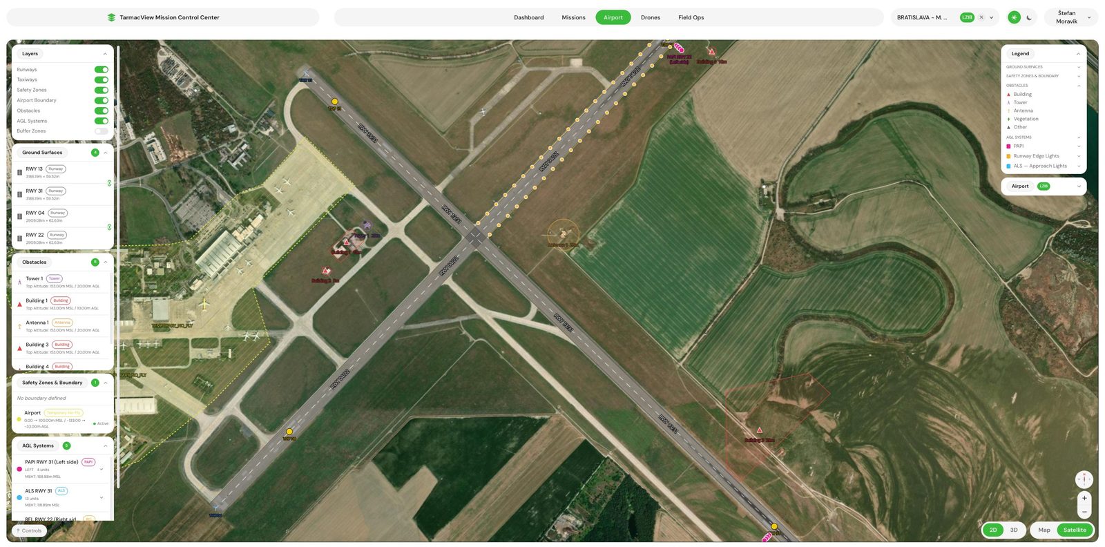
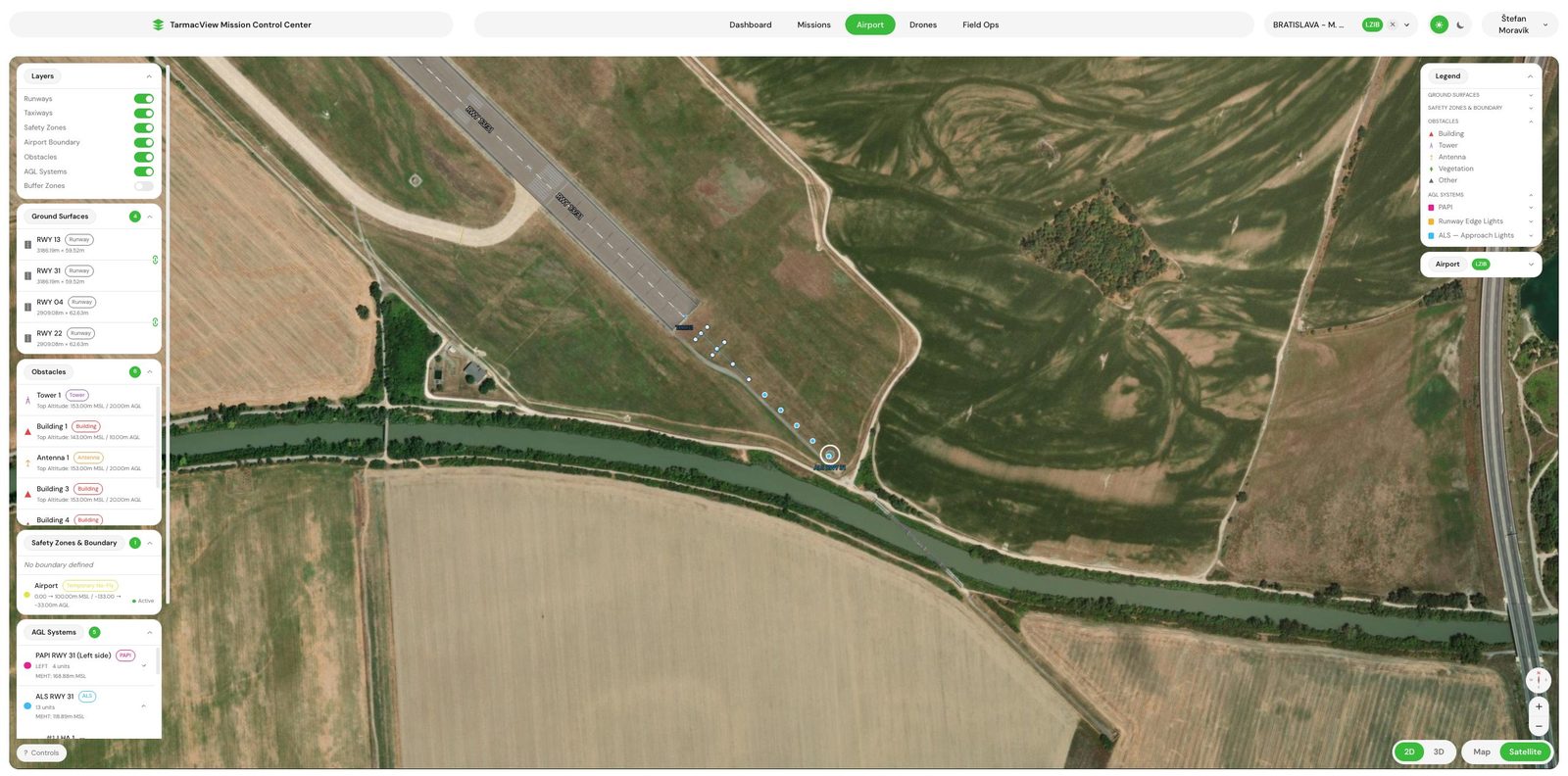
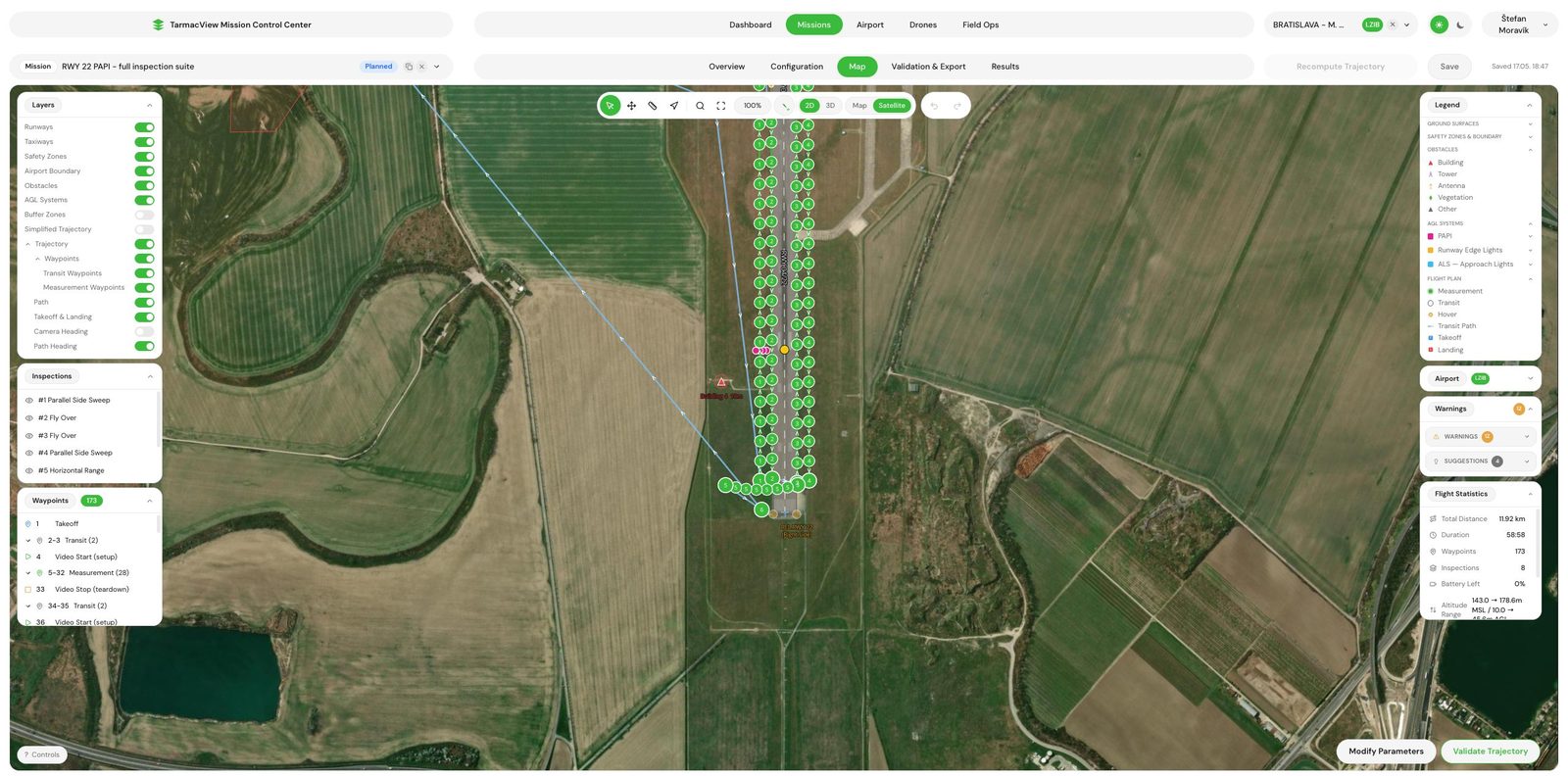
A fly-over tracks directly above the lights end to end, so each unit is measured looking down its own beam. A parallel side sweep runs offset outboard of the row at a fixed standoff, which is how beam shape across the horizontal sector gets sampled. An observation arc sits out on the approach at the glide path height and looks back down the runway, which is the pattern the crew actually sees. Every pass is generated from your surveyed light positions, so the drone frames each unit rather than hunting for it.
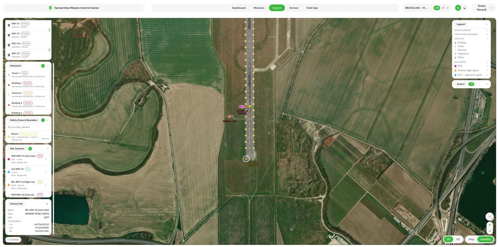
Every unit is tracked across the footage and scored on its own: intensity at fixed reference distances, how fast the beam rises and falls, beam width and symmetry, CIE chromaticity and colour temperature, halo and edge sharpness, plus its spacing and alignment against the surveyed row. Because the whole row is measured in one pass, each unit is also scored against its neighbours, which is what catches the fixture still lit but running well under the rest of the row. A gap where a unit should be is reported as a missing light, not as silence.
The runway lighting rows of the visual aids protocol, each with the tolerance it is judged against.
The runway light pattern is the correct shape for the runway and its category.
Every unit emits the correct colour for its position in the pattern, and no red filter has faded out of specification.
Threshold, edge and end light intensity, and the ratio between the parts of the system, are correct along the whole runway.
The pattern stays visible across the sector either side of the runway axis.
The pattern stays visible through the approach sector as the aircraft descends.
Every unit changes intensity together and by the commanded step, and the runway system tracks the approach system without visually vanishing beside it.
Each unit sits at its surveyed position along the row, and any gap left by a dark unit is reported against the light it belongs to.
The pattern is unchanged when the airfield transfers to its standby supply.
No light near the runway can be mistaken for the runway system, and none dazzles the crew.
You name the runways, whether threshold, end and centre line lights are in scope, and whether a surveyed layout of the units exists. We agree the intensity steps to be checked and the protocol template your authority wants. Output is a scope note. If the layout does not exist, the first visit produces it.
The fly-over, the side sweep and the observation arc are generated from the unit positions, the row length and the camera optics, so every unit is framed at the distance and angle the measurement needs. Output is a validated mission and a capture window request to your tower, plus a request to your lighting control room for the steps to be commanded.
Flown between aircraft movements, about an hour on site per runway. The row is flown end to end at each intensity step in scope, and the transfer to standby power is watched where it is part of the protocol. If a movement interrupts a pass, the pass is reflown unchanged rather than stitched.
Each unit is tracked through the footage and its intensity, colour, beam shape and position are extracted. Every figure is then set against the row, so a unit is scored both against the standard and against its neighbours. Frames the tracker is not confident about are held for review rather than dropped.
The runway lighting rows of the visual aids protocol are filled in your authority's wording, with a figure and a verdict per unit and a ranked list of the units to attend to. Delivered the same day, with the flight record and the source frames attached.
We walk your electrical manager through the units that moved since the last visit and the ones that sit furthest from the row. Anything disputed is re-examined against the retained footage rather than re-flown.
An edge light row is specified as a pattern, and a pattern degrades in a way that no single fixture reveals. A unit at three quarters of its neighbours is invisible on a night walk and obvious on an approach. The inspection therefore measures every unit from the same set of positions, down its beam from above, across its beam from the side and along the row from the approach, and sets each figure against the rest of the row. The light intensity of a unit is reported as a ratio to its neighbours and to its own dimming steps, which is exactly what the uniformity and dimming rows of the protocol ask for.
The ratio is not the whole record. The camera is characterised against a calibrated source in the laboratory before it flies, so every unit also gets a figure in candela, corrected for the measured range from RTK positioning and for the atmospheric transmission recorded on the day. The correction is printed beside the value. That is a measurement in absolute units, not a certificate. Certified photometry of an individual fixture still needs a calibrated instrument at the unit, and it stays outside this service.
What the pass adds on top of the absolute figure is consistency. Every unit in the row is measured from the same positions at one detection threshold on every visit, which a walked check cannot do, so a unit drifting away from its neighbours is named before it fails a limit.
The chromaticity of every unit comes from the same footage, which is how a faded filter on the red section over the last part of the runway is caught, and the light pattern as a whole is checked from the observation arc, which is the view a crew has. Each unit’s position is fixed by RTK positioning , so spacing and alignment are measured against the surveyed row and a dark unit is reported against the position it should occupy rather than as a shorter row. A runway edge light that has been knocked off its aiming shows up in the beam symmetry figure before it shows up as an outage.
Retained footage is what makes a disputed figure checkable. If your electrical manager questions a unit’s ratio, the frames it was read from are still there with their positions, and the figure can be recomputed in front of them. That is also what lets the next visit report change, unit by unit, rather than a fresh opinion of the row.
There is no published rate for this service, because a single 1,200 metre row and two 3,000 metre runways with threshold, end and centre line lights are different days of work off the same method. The quote gives your figure, and the pricing page describes the combined visit.
Three things can stop or degrade an inspection, and each has an owner.
Fog, precipitation and wind above the drone's limit stop the capture, and a wet runway changes the way a unit reads from above. The mission is flown when the window opens rather than measured through the weather. This is the most common reason a date moves.
The capture needs tower coordination, at most aerodromes an escort, and a control room that can command the intensity steps and the standby transfer while the drone is in position. All three sit with the aerodrome operator and are worth confirming before travel is booked.
A unit is scored against its surveyed position and its neighbours. If units were moved, added or removed since the layout was made, the scoring is against the wrong row. We agree at scoping whose layout is used, and a first visit without one produces it.
Drone approach lighting system inspection from the pilot's eye view. Pattern, colour, intensity, coverage and the flashing row verified unit by unit,…

What ICAO Annex 14 requires of runway edge lights, what it leaves open, and how intensity, colour and coverage are actually measured in the field.
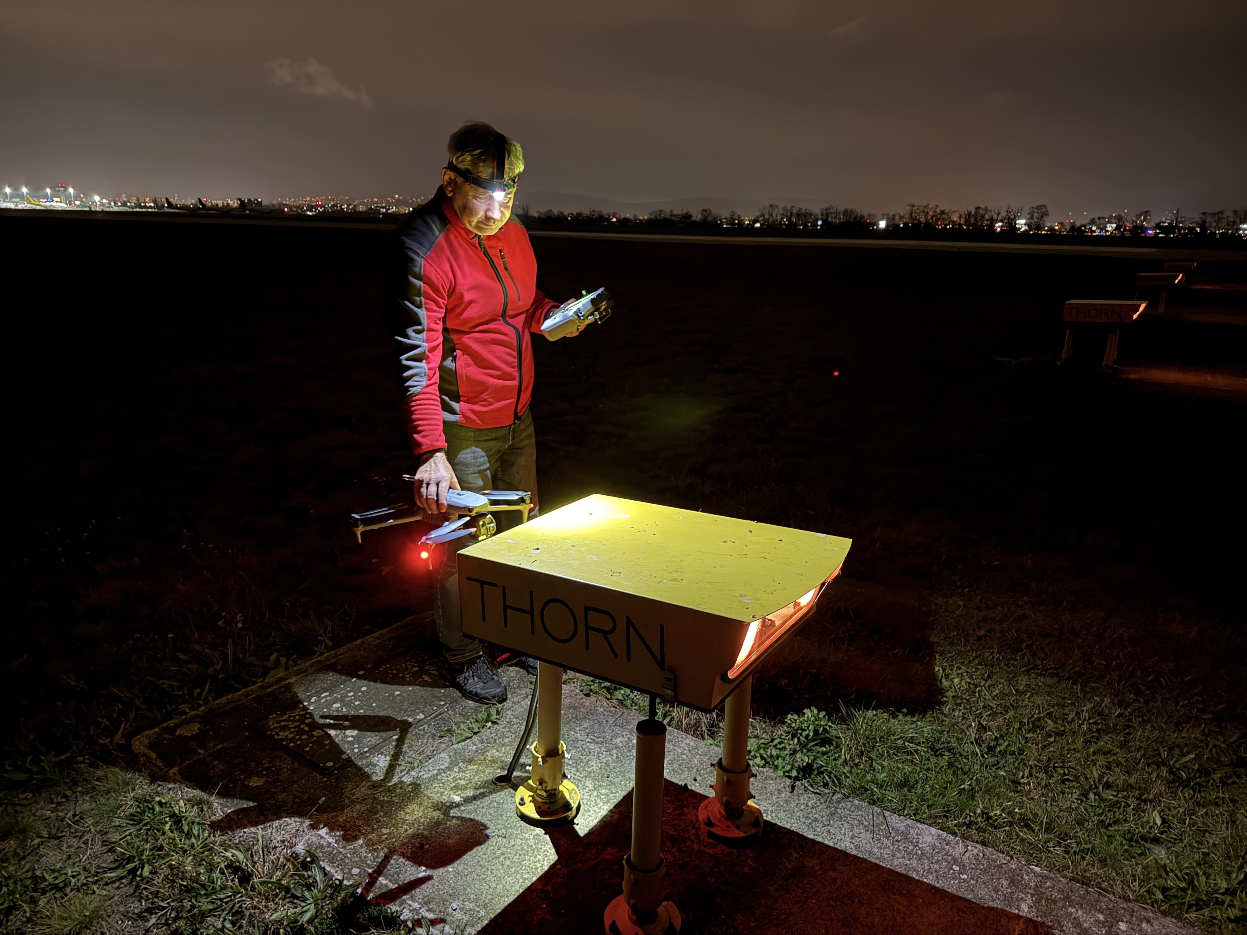
Drone PAPI inspection. Each unit's transition angle, colour, intensity balance and surveyed position measured, with a same-day protocol to ICAO, EASA…
Send the aerodrome, the runways and whether the edge lighting has a surveyed layout. That is enough to scope. You get a written scope note and a price back within two working days, and the scope note is not binding until you accept it.
Cookie Consent
We use cookies to enhance your browsing experience and analyze our traffic. See our privacy policy.